

Page 1
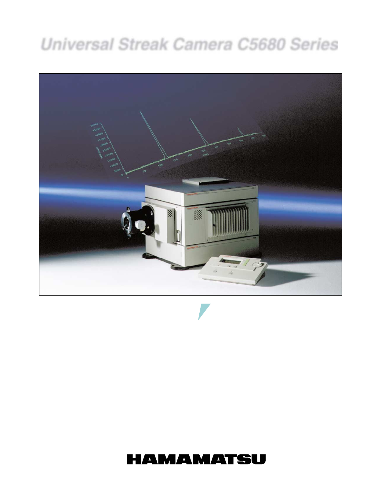
Universal Streak Camera C5680 Series
Measurements Ranging From X-Ray to Near Infrared With a Temporal Resolution of 2 ps
The streak camera is an ultra high-speed
detector which captures light emission
phenomena occurring in extremely short
time periods. Not only can the streak camera
measure intensity variations with superb
temporal resolution, but it can also be used
for simultaneous measurement of the spatial
(or spectral) distribution.
The C5680 Streak Camera Series is a
universal streak camera which incorporates
all of the specialized technology and
expertise HAMAMATSU has acquired in over
20 years of research. The streak tubes are
manufactured on a regular production
schedule at Hamamatsu to provide
consistency and reliability. Special requests
and custom designs are also available.
APPLICATIONS
•
Measurement of electron bunch for
synchrotron and LINAC applications
•
Research involving X-ray lasers, free
electron lasers, and various other types
of pulsed lasers
•
Plasma light emission, radiation, laser
ablasion, combustion and explosions
•
Fluorescence lifetime measurement,
transient absorption measurement,
time-resolved raman spectroscopy
•
Optical soliton communications, response
measurement with quantum devices
•
Lidar Thomson scattering, laser distance
measurement
Page 2
FEATURES
•
Temporal resolution of within 2 ps
A temporal resolution of 2 ps is achieved for both synchroscan
and single shot.
Several plug-in module, operating mode.
•
Accommodates a diverse range of experimental setups
•
from single light emitting phenomena to high-speed
repeated phenomena in the GHz.
•
Can be used in X-ray to near infrared fields
By selecting the appropriate streak tube (light sensor), the
C5680 can be used in a wide range of measurement applications, from X-rays to near infrared light.
Simultaneous measurement of light intensity on
•
temporal and spatial (wavelength) axes
Spectrograph can be placed in front of the streak camera, to
convert the spatial axis to a wavelength axis. This enables
changes in the light intensity to be measured over various
wavelength (time-resolved spectroscopy).
•
Ultra-high sensitivity (detection of single photons)
The streak tube converts light into electrons which are then
multiplied by an electron multiplier. This enables detection of
extremely faint light (at the single-photon level).
(See photon counting integration principle)
IEEE-488 (GP-IB) control
•
Computer control enables remote control and advanced
measurements to be performed out using very simple operation.
•
Diverse selection of peripheral equipment
A full lineup of peripheral devices is available, including
spectroscopes, optical trigger heads, and expansion units.
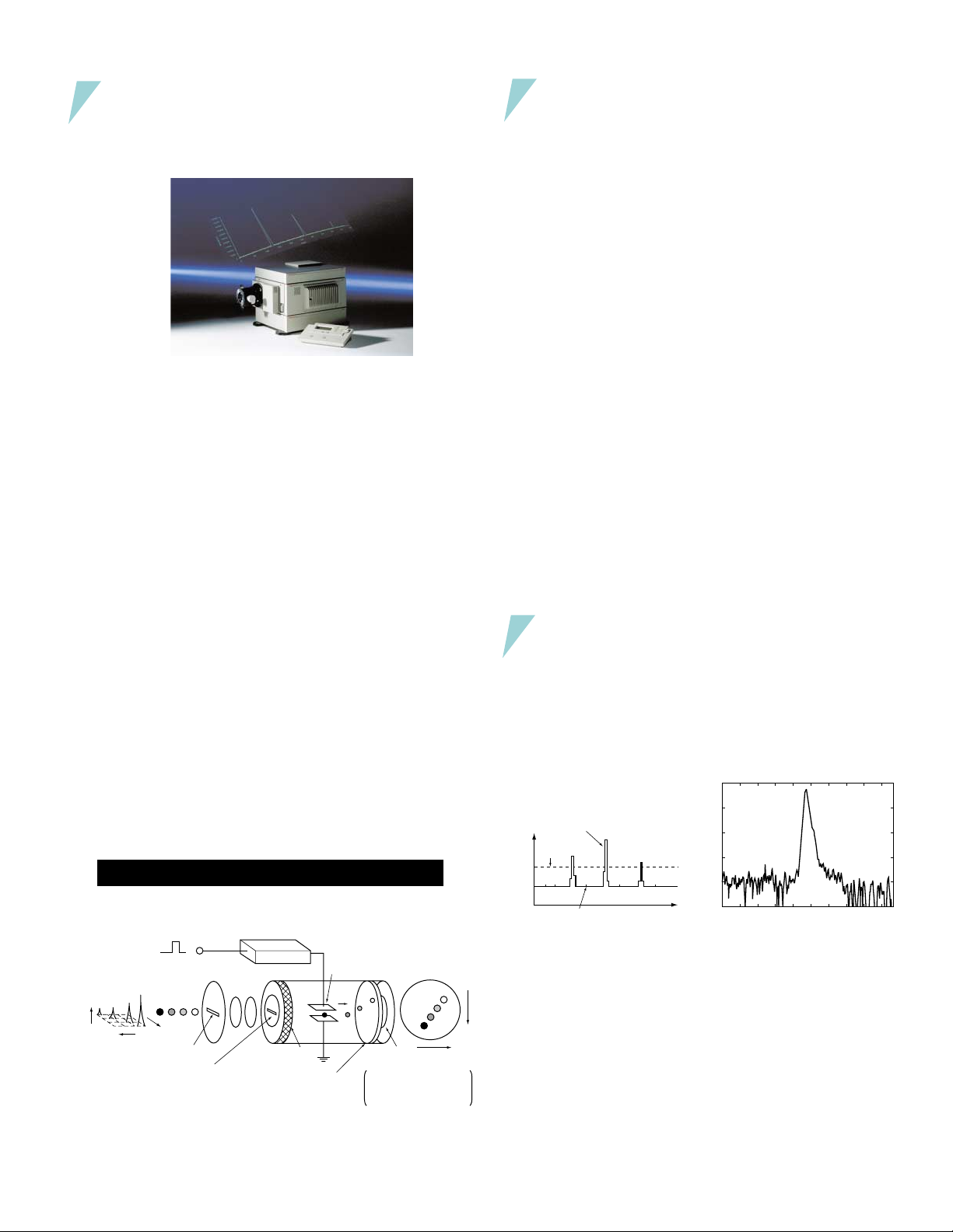
The operating principle of the streak camera
Sweep electrode
(where electrons
are swept in the
direction from top
to bottom)
MCP
(which multiplies
electrons)
Phosphor screen
(electrons → light)
The intensity of the incident light
can be read from the brightness
of the phosphor screen, and the
time and space from the position
of the phosphor screen.
Optical
intensity
Time
Incident light
Trigger signal
Space
Slit
Photocathode
(light → electrons)
Sweep circuit
Lens
Accelerating electrode
(where electrons
are accelerated)
Streak image
on phosphor screen
Time
Space
OPERATING PRINCIPLE
The light pulse to be measured is projected onto the slit and is
focused by the lens into an optical image on the photocathode
of the streak tube. Changing the temporal and spatial offset
slightly each time, four light pulses, each with a different light
itensity, are introduced through the slit and conducted to the
photocathode.
Here, the photons are converted into a number of electrons
proportional to the intensity of the incident light. The four light
pulses are converted sequentially to electrons which are then
accelerated and conducted towards the photocathode.
As the group of electrons created from the four light pulses
passes between a pair of sweep electrodes, a high voltage is
applied (see above), resulting in a high-speed sweep (the electrons are swept in the direction from top to bottom). The electrons are deflected at different times, and at slightly different
angles in the perpendicular direction, and are then conducted
to the MCP (micro-channel plate).
As the electrons pass the MCP, they are multiplied several
thousands of times and are then bombarded against the phosphorscreen, where they are converted back into light.
The fluorescence image corresponding to the first incident
light pulse is positioned at the top of the phosphor screen, followedby the others, with images proceeding in descending order; inother words, the axis in the perpendicular direction on
the phosphor screen serves as the temporal axis. The brightnesses ofthe various fluorescence images are proportional to
theintensities of the corresponding incident light pulses. The
positions in the horizontal direction on the phosphor screen
correspond to the positions of the incident light in the horizontal direction.
THE PRINCIPLE OF PHOTON COUNTING INTEGRATION
Photoelectrons given off from the photocathode of the streak
tube are multiplied at a high integration rate by the MCP, and
one photoelectron is counted as one intensity point on the
phosphor screen. A threshold value is then used with this photoelectron image to clearly separate out noise.
Separation of Photoelectron
Image and Noise
A/D
conversion
Photoelectron image
value
Threshold
value
Signal output from CCD camera
Noise
Time
(wavelength)
Positions in the photoelectron image which are above the
threshold value are detected and are integrated in the memory,
enabling noise to be eliminated completely. This makes it possible to achieve data measurements with a high dynamic range
and high S/N.
Photon Counting Integration
0ps
200ps400ps 600ps800ps 1ns 1.2ns 1.4ns 1.6ns 1.8ns
Light source: PLP (λ = 800 nm)
Integration time: 1 min.
2
Page 3
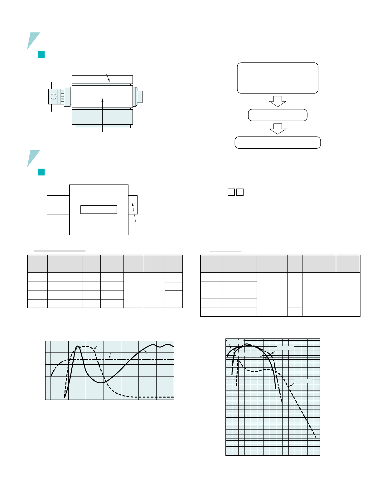
FUNCTION CONFIGURATION
1
C5680 Main Unit (with power supply and camera controller)
Function expansion unit
£
SPECIFICATIONS
1
C5680 Main Unit
1
Input
optics
system
1 Input Optics System
™Sweep unit
2
Streak tube
3
Output
format
Selection of C5680 main unit
Selection of input optics system
Selection of streak tube
Selection of output format
Selection of sweep unit
Selection of function expansion unit
[Suffix (Model No.)]
One of the following suffixes is appended to the model number of
the C5680, depending on the type of streak tube and output format
used.
C5680–
..........
1 Accommodates 200 nm to 850 nm, 1 MCP
2 Accommodates 300 nm to 1600 nm, 1 MCP
. . . .
2 Lens output type
3 Video output type
3 Accommodates 115 nm to 850 nm, 1 MCP
4 Accommodates 200 nm to 900 nm, 1 MCP
5 Accommodates 200 nm to 850 nm, 2 MCPs
2 Streak Tube
Model
Name
A1976-01
A1974
A1974-01
A1976-04
Spectral
Transmission
200 nm to 1600 nm
400 nm to 900 nm
400 nm to 1600 nm
200 nm to 1600 nm
Effective
F Value
Image
Multiplica-
tion Ratio
5.0 1 : 1
1.2 1 : 1
1.2 1 : 1
3.5 1 : 1
The A1974 and A1974-01 are optional units.
100
80
60
40
Transmittance (%)
20
0
Spectral transmittance of input optics system
A1974
A1976-01
200 400 600
800
Wavelength (nm)
1000 1200 1400 1600
Slit
Width
0 to 5 mm
A1974-01
Slit Width
Reading
Precision
5 µ
m
Overall
Length
98.2 mm
159 mm
159 mm
98.2 mm
Model
Name
N5716
N5716-02
N5716-01
N5716-03
N5864
Spectral
Response
Characteristic
200 nm to 850 nm
300 nm to 1600 nm
115 nm to 850 nm
200 nm to 900 nm
200 nm to 850 nm
Effective
Photocathode
Size
• 0.15 × 5.3 mm
Lens output
type
• 0.15 × 4.8 mm
Video output
type
MCP
Gain
3 × 10
6 × 10
3
5
Phosphor
Screen
• Photocathode
characteristic
P-43
• Fiber-optic output
• Effective photo-
cathode size
•
18 mm
Spatial
Resolution
25 lp/mm
or more
centered
on
photocathode
X-ray streak cameras designed for use with 10 eV to 10 keV can
also be selected.
Spectral response of the streak tube
5
10
10
10
10
10
Radiant sensitivity (µA/W)
10
10
N5716-01
4
3
2
1
0
-1
N5716, N5864
N5716-03
N5716-02
-2
10
200 400 600
800 1000 1200 1400 1600
Wavelength (nm)
3
Page 4
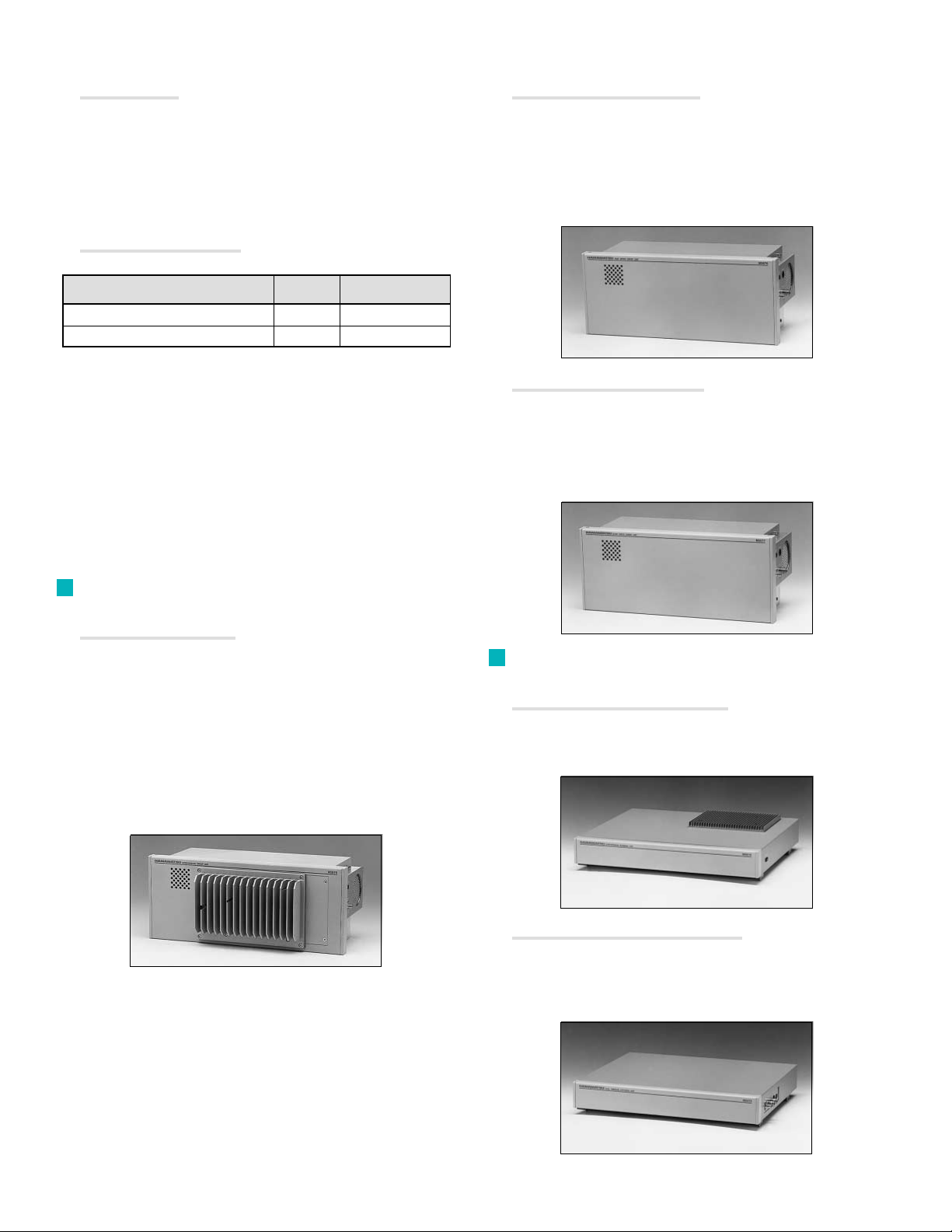
3 Output Formats
• Lens output .....
• Video output ...
4 Other 5680 Specifications
Magnification
Effective F value
F-mount
Signal format
Coupling method
Resolution
• Gate
Gating Method
MCP + horizontal blanking
MCP + horizontal blanking + photocathode
1 : 0.7 (50 mm : 35 mm)
F/2.0
CCIR or RS-170
Fiber optics
768 × 493 or 756 × 581 pixels
Gate Extinction Ratio
1 : 106 min.
8
1 : 10
min.
Gate Time
50 ns to continuous
50 ns to continuous
•
M5676 Fast Single Sweep Unit
Temporal resolution........................
Sweep time
Trigger jitter ................................
Trigger delay
Maximum sw eep repetition frequency (max.)
Trigger signal input .......................
Video output type ..
Lens output type...
................................
Better than 2 ps at 800 nm (1.5 ps typ.)
0.15, 0.5, 1, 2, 5, 10, 20, 50 ns/full screen
.....
0.2, 0.5, 1, 2, 5, 10, 20, 50 ns/full screen
.....
Better than 20 ps
Approx. 13 ns (fastest range)
10 kHz
...
± 5 V/50 Ω
•
Gate trigger input
• ......................................120 ns max.
Gate trigger delay time
• ............2 MHz
Max. horizontal blanking repetition frequency
• ......................... 10 kHz
Max. MCP gate repetition frequency
• ........... 10 kHz
Max. photocathode gate repetition frequency
• Monitor out signal................
• ............................... IEEE-488 (GP-IB)
Interface
• Status output .......................
• .........................
Line voltage
• .............
Power consumption
2
Sweep units
.......................................
3.5 Vp-p (typ.)
D sub-connector DB-25S, 16-bit
parallel output, open collector
AC110/117/220/240 V, 50/60 Hz
Approx. 180 V
3.5 V to 5.0 V/50 Ω
•
A
(Plug-in: built into main unit)
• M5675 Synchroscan Unit
Temporal resolution...................
Sweep range
Sweep range ........................... 4 selectable range
Synchroscan frequency ............
Synchronous frequency range ..
Trigger jitter ...........................Better than temporal resolution
Trigger signal input
Video output type .
Lens output type...
....................
Better than 2 ps at 800 nm (N5716-01)
Better than 3 ps at 800 nm (N5716-02)
150 ps to 1/6 fs (fs:synchroscan frequency)
200 ps to 1/6 fs
Factory set within a range of 75 MHz
to 165 MHz
fs ± 0.2 MHz (fs = synchroscan frequency)
–3 dBm to 17 dBm / 50 Ω
• M5677 Slow Single Sweep Unit
Temporal resolution.......................
Sweep time
Trigger jitter
Trigger delay
Maximum sw eep repetition frequency (max.)
Trigger signal input .......................
Function Expansion Units (connected to
3
...................................
...................................
.................................
Better than 50 ps
50 ns to 1 ms/full screen
Better than temporal resolution
Approx. 45 ns (fastest range)
2 MHz (fastest range)
..
± 5 V/50 Ω
top of main unit)
•
M5678 Synchronous Blanking Unit
(designed for use in conjunction with M5675 Synchroscan)
Synchroscan frequency ........
Horizontal shift width
.............
Factory set within a range of 75 MHz to 165 MHz
2.5 mm or 11 mm (at phosphor screen)
M5679 Dual Time Base Extender Unit
•
(Can be used in conjunction with all sweep units)
Sweep time
Maximum sw eep repetition frequency (max.)
Trigger signal input
4
.....................................
..........................
10 ns to 100 ms/full screen
.
...
10 Hz
± 5 V/50 Ω
Page 5
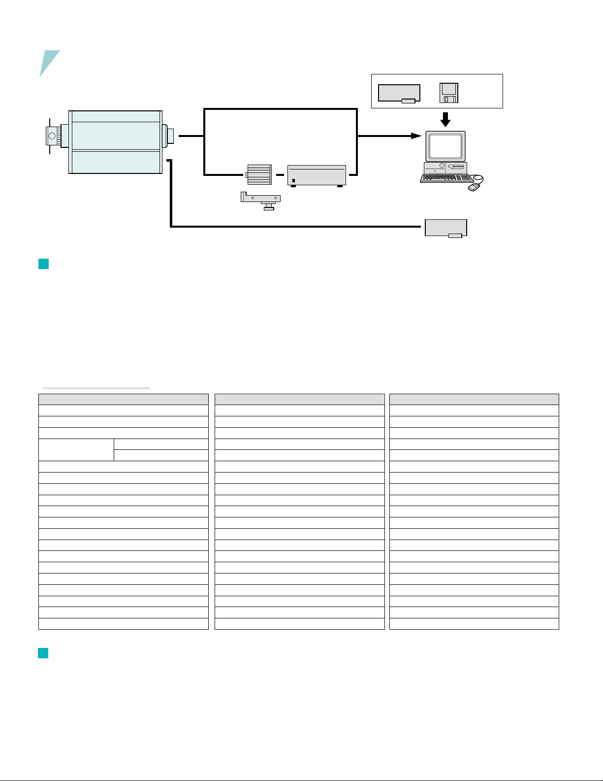
READOUT SYSTEM (HPD-TA)
Input optics
1
2
format
Femtosecond Streak Camera
Video output (Video CCD Camera)
Output
Lens output
Cooled digital camera
C4742-95 Series (ORCA)
Camera head
Control unit
Frame Grabber
Readout system
3
(HPD-TA)
Streak Image
Analysis
Software
(IBM PC/AT Compatible)
Streak Image
Analysis Systems
for IBM
Personal computer
®
PC/AT
Mount Table A1471-12
4
General Outline
The HPD-TA (Temporal Analyzer) is a high-performance digital data
acquisition and control system specifically designed to read out images from the Hamamatsu streak camera’s phosphor screen. It enables precise, quantitative acquisition and pre-analysis of two dimensional streak data that includes photon counting plus a full range of
data correction and calibration possibilities. It possible to select the
best camera for a given streak configuration and application. The
camera is connected to an IBM-compatible PC/AT via a frame grabber board that can support real-time data transfer.
•Functions & Specifications
Items
Items
Camera model
Coupling method
Resolution (pixels)
Dynamic range
Single frame
Integration
Frame rate
Superpixel mode
Subarray scan mode
Single exposure time
Analog integration
Photon counting
Dark correction
Shading correction
Curvature correction
Calibration
Multiple profiles
Data export (images)
Data export (profiles)
Streak camera interface
Other devices interf
Cooled CCD version
C4742-95 Series (ORCA)
Relay lens
1280 × 1024
10 or 12 bits
9 Hz (normal) / 18 Hz (super pixel)
132 µs to 10 s
on chip / into memory
linear / nonlinear, both ax
up to 10
Binary,TIFF, ASCII
GPIB or StatusPort
GP-IB board
The HPD-TA allows the remote control of the C5680 via GPIB interface. The entire system is controlled through a powerful but
userfriendly software application that runs on a Microsoft Windows platform.
* A read out system based on the
Macintosh® computer is also
available.
Please consult with our sales office for more details.
Video version
Video CCD
Fiber optics
756 × 581
8 bits
16 bits
16 bits
30 Hz
•
•
–
–
40 ms or 33 ms
into memory
•
•
•
•
•
•
•
•
linear / nonlinear, both axes
up to 10
Binary , TIFF, ASCII
ASCII
ASCII
GPIB or StatusPort
GPIB
GPIB
5
Computer Environment
The HPD-TA requires an industry-standard Pentium-class (or compatible) PC with a 32-bit Microsoft Windows version. A fast, highresolution graphics configuration is recommended. Depending on
the streak camera system configuration, a number of PCI and/or
ISA slots as well as a serial interface port may be occupied. (Please
consult Hamamatsu for a detailed specification for a given case.)
5
Page 6
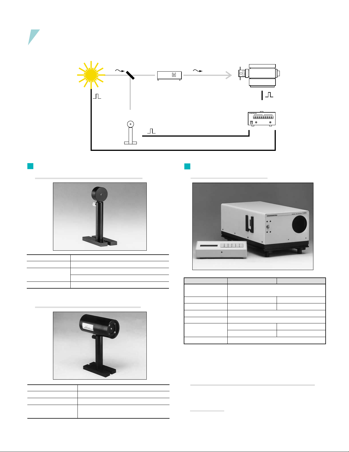
PERIPHERAL EQUIPMENT
Light-emitting
phenomenon
§Optical trigger
6
Optical Trigger (PIN diode head)
• PIN Diode Head C1083-01 (for Low Repetition)
¶Input section
7
•
Streak camera
•Trigger unit
Input Section
Spectroscopes C5094 and C5095
Spectral response 400 nm to 1100 nm
Rise time 0.8 ns
Dimensions/weight
Power supply +22.5 V (battery)
Head: 100 (W) × 160 to 235 (H) × 50 (D) mm/400 g
Po wer supply unit: 100 (W) × 83(H) × 100 (D) mm/400 g
• PIN Diode Head C1808-03 (for High Repetition)
Minimum input level
Saturation output level
Frequency band
Power supply
6
1 mW (f=80 MHz, λ=800 mm, FWHM<1 ps)
Approx. 1.5 Vp-p (50 Ω)
<100 MHz
INPUT Voltage range 100 V to 240 V Input
power supply frequency range 50/60 Hz
C5094 C5095
Optical layout Czerny-Turner model
Focal distance 250 mm 500 mm
F value
Incident light slit width
Grating Up to 3 can be installed simultaneously
Reciprocal dispersion 2.5 nm/mm 1.5 nm/mm
Wavelength resolution < reciprocal dispersion × 0.06
The following are needed in order to connect these units to the C5680:
• A spectroscope mounting table
• A spectroscope adaptor
• A light source for wavelength axis calibration (mercury lamp, etc.)
Fiber-optic Input Optics System (FC Connector) A6368
•
This fiber-optic input optics system can be connected in place of
theincident light slit in the C5680.
Objective Lens
•
Connecting a C-mount adaptor to the incident light slit section of the
C5680 enables attachment of a C-mount objective lens. F-mount objective lenses can also be attached using an FC converter.
(with toroidal mirror for aberration correction)
48
Variable between 10
(when using 1200 gr/mm) (when using 1200 gr/mm)
µ
m to 2,000 µm
Page 7
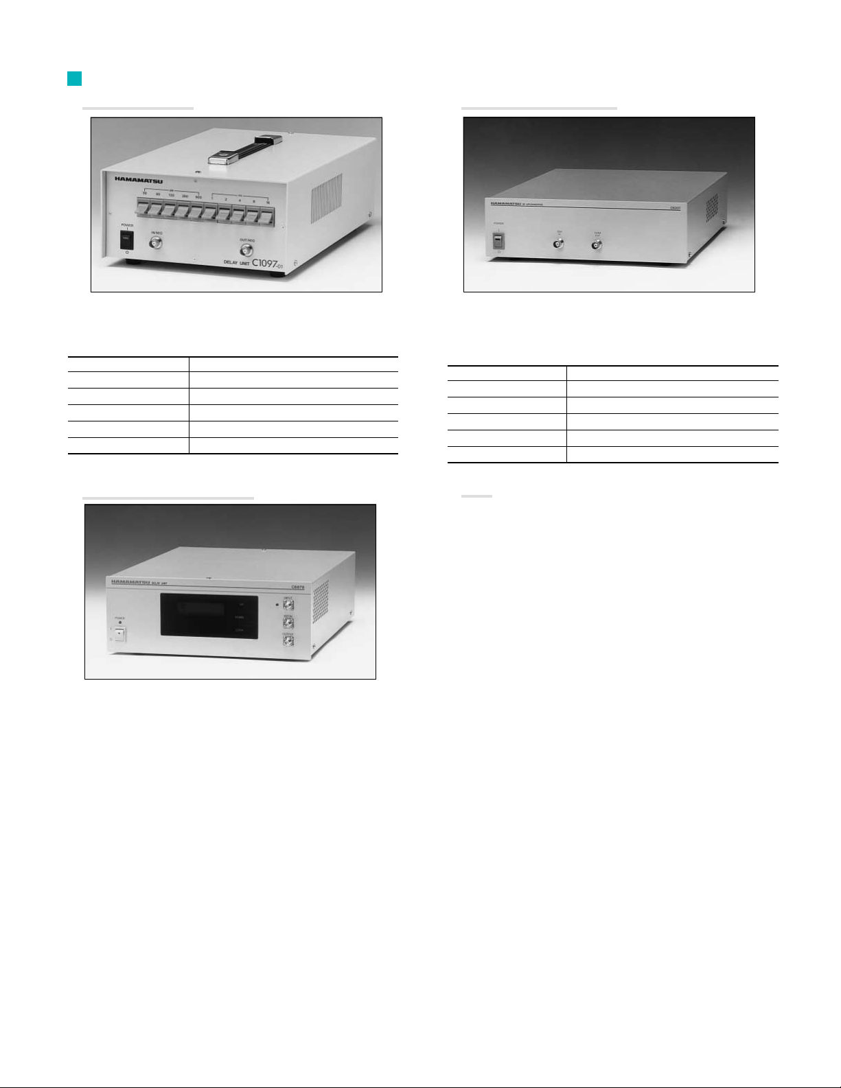
Trigger Units
8
• Delay Unit C1097-01
•
RF Up Converter Unit C6207
This unit can be used to align the operation timing of the streak
camera with the target phenomenon.
*The C1097-04, which has a GP-IB interface, is also available.
Variable delay range
Delay setting range
Minimum delay time
Maximum input voltage
Power supply
External dimensions/weight
0 to 31.96 ns
30, 60, 120, 250, 500 ps, 1, 2 4, 8, 16 ns
Approx. 12 ns
30 V
AC85 V to 250 V
215 (W) × 350 (D) × 102 (H) mm/3.4 kg
• High-stability Delay Unit C6878
Used in combination with a synchroscan unit, this unit is used to
adjust the delay times of trigger signals. In addition, the amount
by which trigger signals are delayed is adjusted automatically,
while monitoring the sweep signal, enabling stable acquisition of
streak images over a long period of time.
This outputs an output signal of 100 MHz synchronized to the
10 MHz input signal.
Inputting reference output signals from a commercial frequency
synthesizer enables stable synchroscan triggers to be obtained.
Input signal frequency
Input level
Output frequency
Output signal level
Timing jitter
Power supply
Other
•
Numerous other peripheral devices are also available, such as
the DG535 Digital Delay Generator and the Picosecond Light
Pulser PLP Series. Please feel free to contact HAMAMATSU
concerning these and other devices.
10 MHz ± 10 Hz
–10 dBm to 0 dBm/50 Ω
100 MHz
3 dBm/50 Ω (typ.)
σ: 1 ps max.
AC100/117/220/240V, 50/60 Hz
7
Page 8
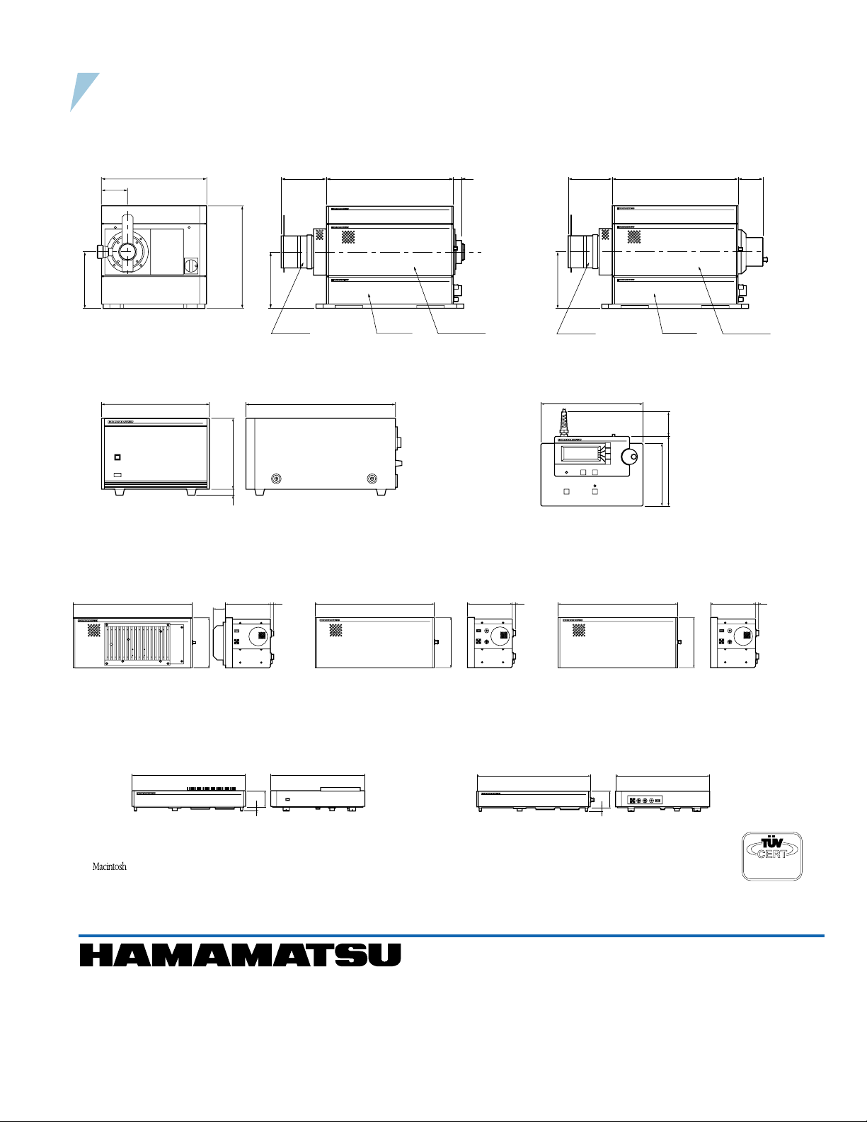
DIMENSIONAL OUTLINES (Unit: mm)
• C5680 main unit
C5680-1X (video output)C5680-0X (lens output)
(approx. 20 kg)
23
128 360 70
160
A1976-01 C5680-1X M5676/M5677
160
300
75
290
128 360
160
A1976-01 C5680-0X M5676/M5677
• Power supply unit (approx. 10 kg) • Remote control unit (approx. 1.2 kg)
230 320
14912
225
135
150 50
• Synchroscan Unit M5675
(approx. 4.1 kg)
360 135 11
38
147
• Synchronous Blanking Unit M5678
(approx. 3.4 kg)
360 300
51.5
12
★ IBM is a registered trade mark of IBM Co.
★ is registered trademark of Apple Computer, Inc.
★ Product and software package names noted in this documentation are trademarks or registered trademarks of their respective manufacturers.
• Fast Single Sweep Unit M5676
(approx. 2.4 kg)
360 135 11
147
• Dual Time Base Extender Unit M5679
(approx. 3.4 kg)
• Slow Single Sweep Unit M5677
(approx. 2.2 kg)
360 135 11
360 300
51.5
12
147
ISO 9001
Certificate: 09 105 79045
• Subject to local technical requirements and regulations, availability of products included in this promotional material may vary. Please consult with our sales office.
• Information furnished by HAMAMATSU is believed to be reliable. However, no responsibility is assumed for possible inaccuracies or omissions.
Specifications and external appearance are subject to change without notice.
© 2003 Hamamatsu Photonics K.K.
Homepage Address http://www.hamamatsu.com
HAMAMATSU PHOTONICS K.K., Systems Division
812 Joko-cho, Hamamatsu City, 431-3196, Japan, Telephone: (81)53-431-0124, Fax: (81)53-435-1574, E-mail:[email protected]
U.S.A. and Canada:
Germany:
France:
United Kingdom:
North Europe:
Italy:
Hamamatsu Photonics Italia S.R.L.: Strada della Moia, 1/E 20020 Arese (Milano), Italy, Telephone: (39)02-935 81 733, Fax: (39)02-935 81 741, E-mail:[email protected]
Hamamatsu Photonic Systems: 360 Foothill Road, Bridgewater, N.J. 08807-0910, U.S.A., Telephone: (1)908-231-1116, Fax: (1)908-231-0852, E-mail:[email protected]
Hamamatsu Photonics Deutschland GmbH: Arzbergerstr. 10, D-82211 Herrsching am Ammersee, Germany, Telephone: (49)8152-375-0, Fax: (49)8152-2658, E-mail:[email protected]
Hamamatsu Photonics France S.A.R.L.: 8, Rue du Saule Trapu, Parc du Moulin de Massy, 91882 Massy Cedex, France, Telephone: (33)1 69 53 71 00, Fax: (33)1 69 53 71 10, E-mail:[email protected]
Hamamatsu Photonics UK Limited: 2 Howard Court, 10 Tewin Road Welwyn Garden City Hertfordshire AL7 1BW U.K., Telephone: (44)1707-294888, Fax: (44)1707-325777, E-mail: [email protected]
Hamamatsu Photonics Norden AB: Smidesvägen 12, SE-171-41 Solna, Sweden, Telephone: (46)8-509-031-00, Fax: (46)8-509-031-01, E-mail:[email protected]
Cat. No. SSCS 1046E07
AUG/2003 HPK
Created in Japan (PDF)
 Loading...