

Page 1
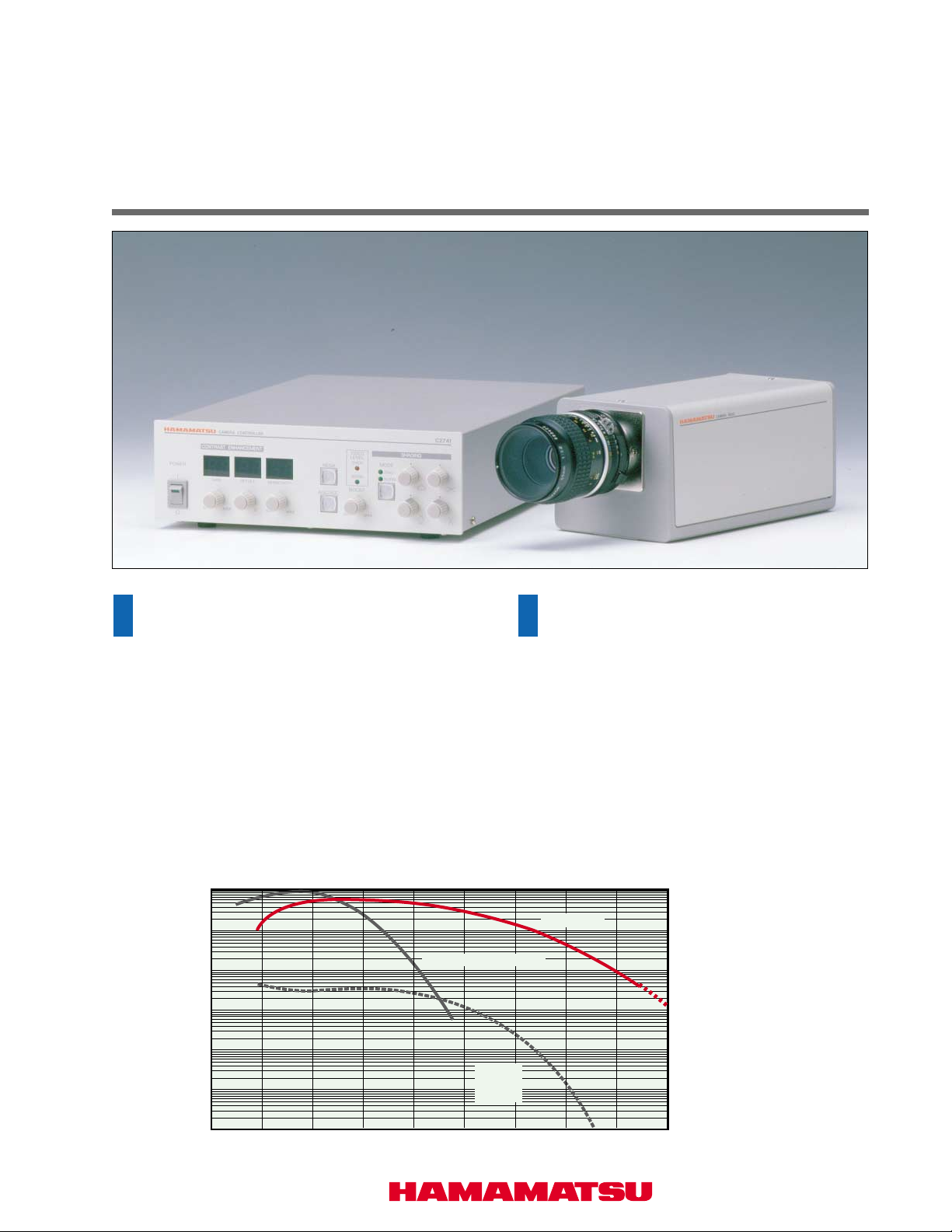
INFRARED VIDICON CAMERA
C2741-03
OUTLINE
The C2741-03 is a high-performance video camera
with various functions that have been developed for
image processing and measurement purposes. The
camera has sensitivity to 1800 nm from a visible
wavelength region. Compared with conventional
surveillance cameras, this camera excels in resolution,
image distortion, stability, etc.
In addition, the camera can be connected to a realtime image processor and measurement system, and
also to a personal computer for use with a video frame
grabber board.
[Spectral Response Characteristics]
0
10
–1
10
–2
10
–3
10
Visible CCD Video Camera
(Lens is optional)
FEATURES
●
Sensitivity to 1800 nm from
visible wavelength region
●
Image processing and
measurement
●
Contrast enhancement
function
C2741-03
–4
10
Relative Sensitivity
–5
10
–6
10
200 400 600 800 1000 1200 1400 1600 2000
Wavelength (nm)
Infrared
Camera
(C5840)
Page 2
APPLICATIONS
● Light intensity measurement in the infrared region
Light intensity measurement of infrared light sources, including
infrared LEDs, transmission characteristic measurement of optical
fibers, etc., and other applications, is possible. In addition, the light
intensity distribution of an infrared light source can be measured
with a real-time image processing system.
● Internal inspection
Internal inspection is possible with an infrared light source. The
camera can be connected to a microscope to look for IC
internal defects.
● Observation and surveillance
This camera can be connected to an infrared floodlight for
surveillance under low illuminated conditions, in a darkroom,
etc.
● Various image processing and measurement
The C2741-03 has been developed for image processing and
measurement. By connecting it to the ARGUS-20 or a realtime image processing system, various measurements, such
as light intensity measurement, width and area measurement,
and position measurement can be performed.
▲ Inspection of IC internal defects
[Real-time image processor ARGUS-20]
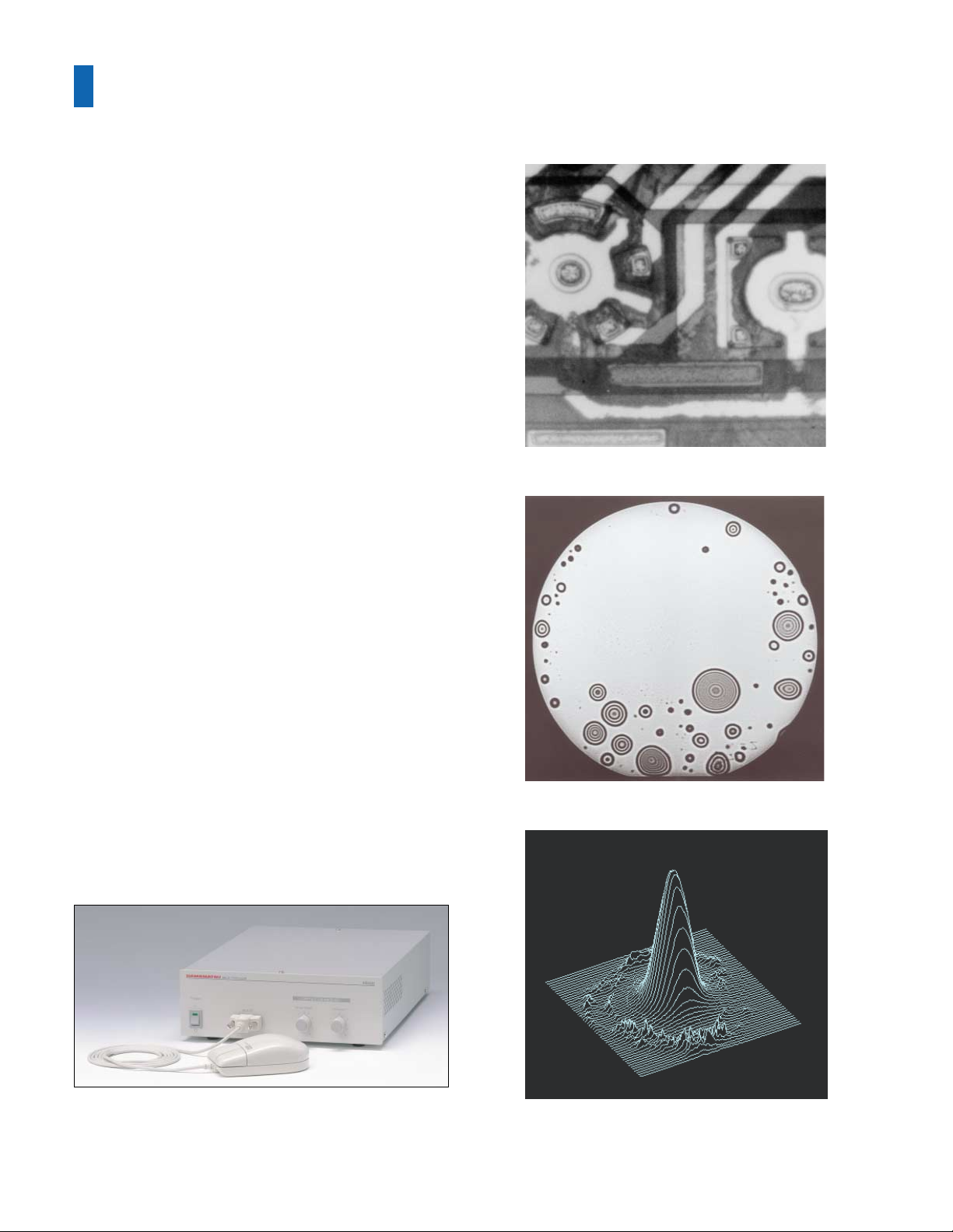
The ARGUS-20 is a real-time image processor that achieves a
high resolution of 1,024 horizontal pixels. A broad range of
image processing functions and measurement functions are
provided, including image subtraction, accumulation, and
recursive filters. A mouse is used, making operation easy.
In addition, a superimpose function enables superimposed
displays of illuminated images, emissions, and fluorescence
emissions, making it possible to identify fluorescence positions
and other elements.
▲ Void detection of bonded wafers
▲ Light intensity distribution of light spot
Page 3

FUNCTIONS
▲ Front panel of camera contr oller
● Contrast Enhancement
The contrast enhancement function amplifies video signals
that are above offset (threshold) level. Using this function, the
low contrast image is enhanced and changed into a clear
image.
Offset level
Before contrast enhancement
▲ Before contrast enhancement
After contrast enhancement
▲
After contrast enhancement
● Shading Corrector
This corrects shading introduced by both the optics and the
imaging tube to help utilize the contrast enhancement feature
most effectively.
● Diagonal Shading Corrector
This corrects the direction of a diagonal.
● Video Booster
The video booster modifies the contrast in dark portions of the
image revealing details which were lost due to their low
intensity.
● Automatic Gain Control: A GC
Excellent overall image contrast can be achieved automatically
using this feature. This eliminates the need for manual
adjustments in situations where light intensity fluctuates over
time.
● Operational Video Output (Optional)
External processing of video signals is simplified by the
operational video output. Operational video does not include
synchronization signals so it can be used to display DC signals
with black lev el as 0 volts.
● All Timing is Crystal Clock Controlled.
By using a crystal oscillator, synchronization is more stable
and higher quality images can be produced . All control
signals, including the deflection frequencies, are derived from
a crystal oscillator.
● High Geometric Stability
It features high geometric (position and dimensional) stability.
Also, highly uniform and accurate images are obtained.
● Level Indicator
Two LEDs, which monitor input light intensity, provide a unique
and rapid method for the accurate determination of the
illumination level required to produce optimal image quality.
In addition, this feature provides a visual indication of
potentially damaging extreme light lev els .
● Video T ube Protection Circuit
A protection circuit has been incorporated to prevent damage
to the imaging tube, should the horizontal or vertical
synchronization signals be lost.
▲ Before processing
▲ After processing
● External Synchronization Control (Optional)
When utilizing external equipment, it may be necessary to
synchronize the scanning of the camera via this optional
control. This circuit automatically switches from the internal to
external synchronization when external horizontal and vertical
signals are provided.
● Video Inverter
The video inverter produces a negative image by inverting the
video intensity values. When used in conjunction with contrast
enhancement, this feature is particularly valuable for improving
detectability and image quality in low intensity regions.
In addition, it is very effective in facilitating the visual
interpretation of high contrast images.
● White Clipper
The white clipper operates to suppress the level of the video
signal when it exceeds a preset level, in order to maintain
consistently high image quality on the TV monitor.
Page 4

PERFORMANCE / SPECIFICATIONS
● Performance
Imaging tube
Spectral response
Horizontal center resolution
Geometric distortion (within inscribed circles)
Shading (within inscribed circles)
Lag
Gamma
S/N
Functions Standard
Optional
● Specifications
Video system
Horizontal scanning frequency
Vertical scanning frequency
Total number of scanning lines
Effective number of scanning lines
Interlace ratio
Aspect ratio
Synchronization system
Output Video signal (composite)
signals
Horizontal vertical
Synchronization signal
Effective scanned area of tube
Lens mount
Operating temperature
Storage temperature
Operating/Storage humidity
Line voltage
Power copmsumption
EIA CCIR
15.734 kHz 15.625 kHz
59.94 Hz 50.00 Hz
525 625
485 509
2 : 1
4 : 3 (horizontal/vertical)
Internal synchronazation
1.0 Vp-p / 75 Ω Two output terminals.
(The composite video signal is output only from VIDEO OUT 1.
Operational video signal is output from VIDEO OUT 2.)
TTL level output, Negative polarity
(External synchronization control(optional) uses this output terminal as input
terminal. The horizontal vertical synchronization signal is not outputted.)
Approx. 12.7 (H) x 9.5 (V) mm
1-inch C-mount
0 to +40 ˚C
-10 ˚C to +50 ˚C
90 % or less (non-condensation)
AC 100/117/220/240 V ±10%, 50/60 Hz
80 VA or less
1- inch Infrared vidicon
400 to 1800 nm
600 TV line (typical value)
± 2.0 (maximum value)
20 % (40 %) (maximum value)
60 % (typical value)
0.6 (typical value)
46 dB (p-p/r.m.s.) (minimum value)
Contrast enhancement
Shading corrector
Diagonal shading corrector
Video booster
Video inverter
Auto gain control (AGC)
Level indicator
Video tube protection
White clipper
External synchronization control
Operational Video output
[Glossary of terms]
● Horizontal center resolution
This shows how far fine structure can be recognized, and it
shows how many stripes TV book display can distinguish at
the interval equivalent to the height (length) of the screen of
video, and white or black is counted as one, respectively.
● Geometric distortion
This is the difference (distortion) between the subject and the
image of the subject on the screen. It is expressed as a
percentage to the vertical height of the screen.
● Shading
Non-uniformity of the video output signal when a video camera
views a uniform source. It is expressed as the difference
between the brightest and darkest signals divided by the
brightest signal and multiplied by 100%. Shading is mainly
caused by non-uniform sensitivity of an image tube surface.
● Lag
A phenomenon caused when some of the output signal lingers
even after the incident light was interrupted. For video cameras,
this means output signal delay in response to the change of
incident light.
● Gamma characteristic
This is the relationship between the signal output and the
incident light. On a logarithmic graph, the former is shown on
the vertical axis and the latter on the horizontal axis; the
gamma characteristic is the slope (tangent) of the resulting
straight line.
● S/N ratio
A comparison of the video signal component and the noise
component that is mixed in. S/N r atio is usually sho wn in dB .
CONFIGURATIONS
● Camera Head
● Camera Controller
● Camera Cable (5 m)
● Video Monitor Cable (BNC-BNC, 3 m)
DIMENSIONAL OUTLINE (UNIT: mm)
● Camera Head (approx. 2 kg)
1-32UN(C-mount)
CAMERA HEAD
98 ± 1
65 ± 0.5
104 ± 1
★ Product and software package names noted in this documentation are trademarks or registered trademarks of their respective manufacturers.
●
Subject to local technical requirements and regulations, availability of products included in this promotional material may vary. Please consult with our sales office.
●
Information furnished by HAMAMATSU is believed to be reliable. However, no responsibility is assumed for possible inaccuracies or omissions.
Specifications and external appearance are subject to change without notice.
© 2001 Hamamatsu Photonics K.K.
HAMAMATSU PHOTONICS K.K., Systems Division
812 Joko-cho, Hamamatsu City, 431-3196, Japan, Telephone: (81)53-431-0124, Fax: (81)53-435-1574, E-mail:[email protected]
U.S.A. and Canada:
Germany:
Hamamatsu Photonics Deutschland GmbH: Arzbergerstr. 10, D-82211 Herrsching am Ammersee, Germany, Telephone: (49)8152-375-0, Fax: (49)8152-2658, E-mail: [email protected]
France:
Hamamatsu Photonics France S.A.R.L.: 8, Rue du Saule Trapu, Parc du Moulin de Massy, 91882 Massy Cedex, France, Telephone: (33)1 69 53 71 00, Fax: (33)1 69 53 71 10, E-mail: [email protected]
United Kingdom:
North Europe:
Italy:
Hamamatsu Photonics Norden AB: Smidesvägen 12, SE-171-41 Solna, Sweden, Telephone: (46)8-509-031-00, Fax: (46)8-509-031-01, E-mail: [email protected]
Hamamatsu Photonics Italia S.R.L.: Strada della Mois, 1/E 20020 Arese (Milano), Italy, Telephone: (39)02-935 81 733, Fax: (39)02-935 81 741, E-mail: [email protected]
1 ± 0.5
2.4 ± 0.2
25 ± 0.5
4-M4 D=5
Hamamatsu Photonic Systems: 360 Foothill Road, Bridgewater, N.J. 08807-0910, U.S.A., Telephone: (1)908-231-1116, Fax: (1)908-231-0852, E-mail: [email protected]
Hamamatsu Photonics UK Limited: 2 How ard Court, 10 T ewin Road, Welwyn Garden City , Hertfordshire, AL7 1BW, U.K., Telephone: (44) 1707-294888, Fax: (44) 1707-325777, E-mail: [email protected]
65 ± 0.5
60 ± 0.5
204 ± 1
1/4-20UNC D=5
9.5 ± 2
40±0.5
● Camera Controller (appro x. 5 kg)
CAMERA CONTROLLER
232 ± 1 308 ± 2
.
C2741
74 ± 17 ± 1
Homepage Address http://www.hamamatsu.com
,
-
ISO 9001
Certificate: 09 105 79045
Cat. No. SICS1085E02
SEP/2001 HPK
Created in Japan (PDF)
 Loading...