

Datasheet BYT71F-800, BYT71F-600, BYT71-800, BYT71-600 Datasheet (SGS Thomson Microelectronics)
Page 1
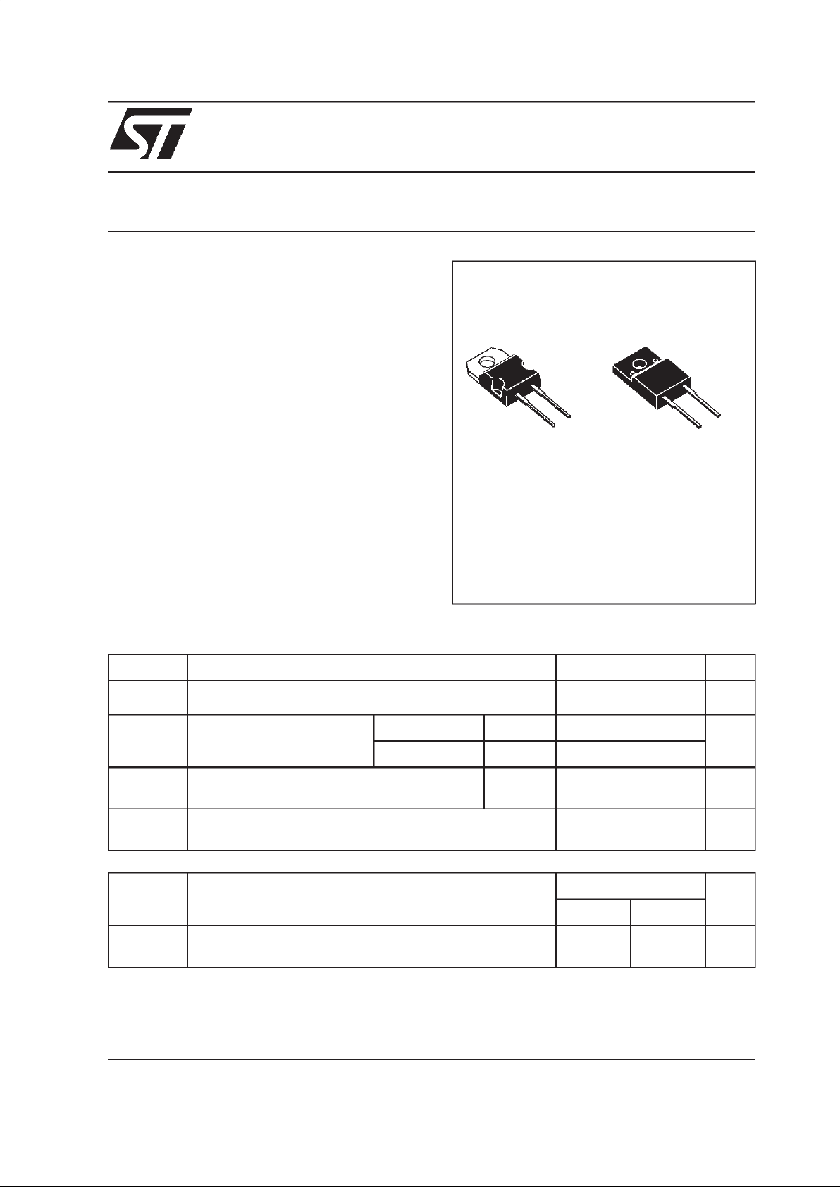
BYT71(F)-800
August 1998 Ed : 3A
FASTRECOVERY RECTIFIERDIODES
Symbol Parameter Value Unit
I
F(RMS)
RMS on-state current 12 A
I
F(AV)
Average forward current
δ = 0.5
TO220AC Tc=130°C6 A
ISOWATT220AC Tc=105°C6
I
FSM
Surge non repetitive forward current tp=10ms
sinusoidal
90 A
Tstg
Tj
Storage and junction temperature range - 65 to + 150
- 65 to + 150
°C
°C
TO220AC
(Plastic)
K
A
.
HIGHVOLTAGECAPABILITY
.
FASTANDSOFT RECOVERY
.
INSULATEDPACKAGE:
insulatingvoltage= 2000V
DC
capacitance= 12 pF
DESCRIPTION
Symbol Parameter BYT71-(F) Unit
600 800
V
RRM
Repetitive peak off-state voltage 600 800 V
ABSOLUTEMAXIMUM RATINGS
FEATURES
Single chip rectifier suited for power conversion
and polarity protection applications.
This device is packaged in TO220AC and in
ISOWATT220AC.
ISOWATT220AC
(Plastic)
K
A
1/7
Page 2

Symbol Test Conditions Min. Typ. Max. Unit
IR** Tj=25°CV
R
=V
RRM
20 µA
Tj= 100°C 1mA
VF*Tj= 100°CI
F
= 6 A 1.3 V
Tj=25°CI
F
= 6 A 1.4
Pulse test : * tp = 380 µs, duty cycle < 2 %
** tp = 5 ms, duty cycle < 2 %
THERMALRESISTANCES
ELECTRICAL CHARACTERISTICS
STATICCHARACTERISTICS
RECOVERYCHARACTERISTICS
Symbol Test Conditions Min. Typ. Max. Unit
trr Tj=25°CI
F
=1A
VR= 30V
dIF/dt = -15A/µs 300 ns
To evaluate the conduction losses use the following equations :
P = 1.15 x I
F(AV)
+ 0.025 x I
F2(RMS)
Symbol Parameter Value Unit
Rth (j-c) Junction to case TO220AC 2.3 °C/W
ISOWATT220AC 4.9
BY T 71(F)-800
2/7
Page 3
I
M(A)
P=5W
P=7.5W
P=10W
T
I
M
=tp/T
tp
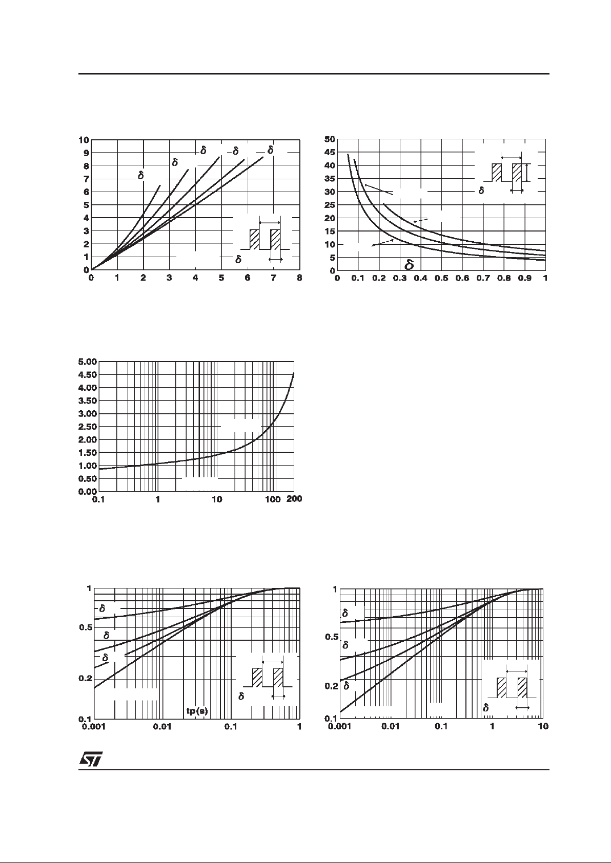
Fig.2 : Peak current versus form factor.
V
FM(V)
Tj=100 C
O
FM(A)
I
Fig.3 : Forward voltage drop versus forward current
(maximum values).
K=Zth(j-c)/Rth(j-c)
SINGLE PULSE
=0.5
=0.2
=0.1
T
=tp/T
tp
Fig.4 : Relative variation of thermal impedance junction
to case versus pulse duration.
(TO 220 AC)
P
F(av)(W)
=0.5
=0.05
=0.1
=0.2
=1
T
=tp/T
tp
I
F(av)(A)
Fig.1 : Average forward power dissipation versus
average forward current.
K=Zth(j-c)/Rth(j-c)
=0.5
=0.2
=0.1
SINGLE PULSE
T
=tp/T
tp
tp(s)
Fig.5 : Relative variation of thermal impedance junction
to case versus pulse duration.
(ISOWATT220AC)
BYT71(F)-800
3/7
Page 4

I
M(A)
IM
=0.5
t(s)
Fig.7 : Non repetitive surge peak forward current versus
overload duration.
(ISOWATT220AB)
F(av)(A)
I
0 25 50 75 100 125 150
0
1
2
3
4
5
6
7
8
Rth(j-a)=15 C/W
o
Rth(j-a)=Rth(j-c)
T
=tp/T
tp
=0.5
Tamb( C)
o
Fig.8 : Average current versus ambient temperature.
(duty cycle : 0.5) (TO 220 AB)
I
F(av)(A)
0 25 50 75 100 125 150
0
1
2
3
4
5
6
7
8
Rth(j-a)=15 C/W
o
Rth(j-a)=Rth(j-c)
T
=tp/T
tp
=0.5
Tamb( C)
o
Fig.9 : Average current versus ambient temperature.
(duty cycle : 0.5) (ISOWATT220AB)
C(pF)
F=1Mhz Tj=25 C
O
V
R(V)
Fig.10 : Junction capacitance versus reverse voltage
applied (Typical values).
IM
=0.5
t(s)
Fig.6 : Non repetitive surge peak forward current versus
overload duration.
(TO 220 AB)
90% CONFIDENCE Tj=100 C
Fig.11 : Recovery charges versus dIF/dt.
BY T 71(F)-800
4/7
Page 5

Tj( C)
QRR;IRM[Tj]/QRR;IRM[Tj=100 C
]
o
o
Fig.13 : Dynamic parameters versus junction
temperature.
I
RM(A)
90% CONFIDENCE Tj=100 C
IF=IF(av)
o
dIF/dt(A/us)
Fig.12 : Peak reverse current versus dIF/dt.
t
fr(us)
0 102030405060708090100
0.00
0.25
0.50
0.75
1.00
1.25
1.50
1.75
2.00
90% CONFIDENCE Tj=100 C
o
dIF/dt(A/us)
IF=IF(av)
Fig.15 : Recovery time versus dIF/dt.
V
FP(V)
0 102030405060708090100
0
5
10
15
20
25
30
35
40
90% CONFIDENCE Tj=100 C
o
dIF/dt(A/us)
IF=IF(av)
Fig.14 : Peak forward voltage versus dIF/dt.
BYT71(F)-800
5/7
Page 6

PACKAGE MECHANICAL DATA
TO220AC Plastic
A
C
D
E
M
L7
H2
ØI
L5
L6
L9
L4
G
F1
F
L2
AK
.
Marking: Typenumber
.
Coolingmethod: C
.
Weight: 1.86g
.
Recommendedtorque value: 0.55m.N
.
Maximumtorque value: 0.70m.N
REF. DIMENSIONS
Millimeters Inches
Min. Max. Min. Max.
A 4.40 4.60 0.173 0.181
C 1.23 1.32 0.048 0.051
D 2.40 2.72 0.094 0.107
E 0.49 0.70 0.019 0.027
F 0.61 0.88 0.024 0.034
F1 1.14 1.70 0.044 0.066
G 4.95 5.15 0.194 0.202
H2 10.00 10.40 0.393 0.409
L2 16.40 typ. 0.645 typ.
L4 13.00 14.00 0.511 0.551
L5 2.65 2.95 0.104 0.116
L6 15.25 15.75 0.600 0.620
L7 6.20 6.60 0.244 0.259
L9 3.50 3.93 0.137 0.154
M 2.6 typ. 0.102 typ.
Diam. I 3.75 3.85 0.147 0.151
BY T 71(F)-800
6/7
Page 7

Information furnished is believed to be accurate and reliable. However, STMicroelectronics assumes no responsIbility for the conse-
quences of use of such information nor for any infringement of patents or other rights of third parties which may result from its use. No li-
cense is granted by implication or otherwise under any patentor patentrights of STMicroelectronics. Specifications mentioned in this pub-
lication are subject to change without notice. This publication supersedes and replaces all information previously supplied.
STMicroelectronics products are not authorized for use as critical components in life support devices or systems without express written
approval of STMicroelectronics.
The ST logo is a registered trademark of STMicroelectronics
1998 STMicroelectronics - Printed in Italy - All rights reserved.
STMicroelectronics GROUP OF COMPANIES
Australia - Brazil - Canada - China - France - Germany - Italy - Japan - Korea - Malaysia - Malta - Mexico - Mo-
rocco - The Netherlands Singapore - Spain - Sweden - Switzerland - Taiwan - Thailand - United Kingdom - U.S.A.
PACKAGEMECHANICAL DATA
ISOWATT220AC Plastic
F
G
F1
H
DE
A
B
L7
Diam
L2
L6
L3
REF. DIMENSIONS
Millimeters Inches
Min. Typ. Max. Min. Typ. Max.
A 4.40 4.60 0.173 0.181
B 2.50 2.70 0.098 0.106
D 2.40 2.75 0.094 0.108
E 0.40 0.70 0.016 0.028
F 0.75 1.00 0.030 0.039
F1 1.15 1.70 0.045 0.067
G 4.95 5.20 0.195 0.205
H 10.00 10.40 0.394 0.409
L2 16.00 0.630
L3 28.60 30.60 1.125 1.205
L6 15.90 16.40 0.626 0.646
L7 9.00 9.30 0.354 0.366
Diam 3.00 3.20 0.118 0.126
.
Marking
: Typenumber
.
Coolingmethod: C
.
Weight: 2 g
.
Recommendedtorque value: 0.55m.N
.
Maximumtorque value: 0.70m.N
BYT71(F)-800
7/7
 Loading...