

Page 1
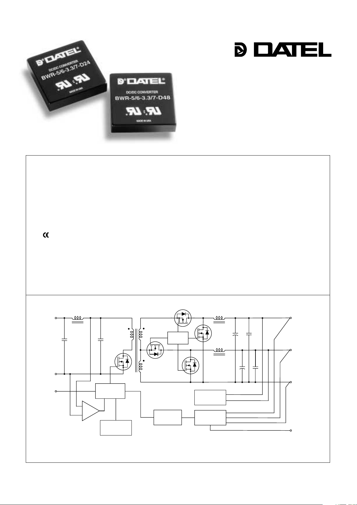
5V and 3.3V, 2" x 2"
33 Watt, DC/DC Converters
Dual Output
Mixed Voltage, BWR Models
Features
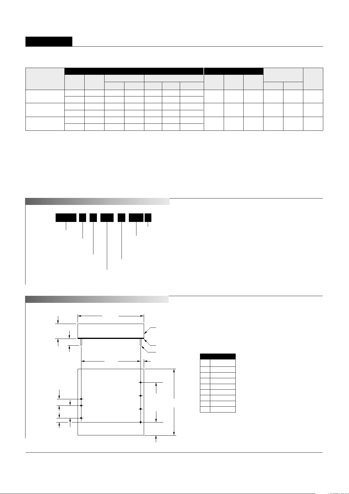
Figure 1. Simplifi ed Schematic
INNOVATION and EX C ELL E N C
E
®
®
■
■
■
■
■
■
■
■
■
■
■
■
■
■
Regulated 3.3V and 5V outputs
5V @ 6Amps/3.3V @ 7 Amps capability
33 Watts total output power
No-load operation
Available input voltage ranges:
10-18V, 18-36V or 36-75V
Small 2" x 2" x 0.45" package
UL1950 and EN60950 safety approvals
mark available (75V-input models)
Continuous short-circuit protection
Fully isolated, 1500Vdc guaranteed
–40 to +100°C operating temperature
Input under and overvoltage shutdown
Output overvoltage protection
Thermal shutdown
DATEL, Inc., Mansfi eld, MA 02048 (USA) · Tel: (508)339-3000, (800)233-2765 Fax: (508)339-6356 · Email: sales@datel.com · Internet: www.datel.com
+INPUT
–INPUT
SWITCH
CONTROL
+5V OUTPUT
+3.3V OUTPUT
OUTPUT
RETURN
TRIM
PWM
CONTROLLER
REFERENCE &
ERROR AMP
OPTO
ISOLATION
ON/OFF
CONTROL
(SYNC)
UV & OV
COMPARATORS
ACTIVE
BLEEDER
THERMAL
SHUTDOWN
For applications requiring 33 Watts of power from 5V and 3.3V, DATEL offers a
new power sharing DC/DC converter capable of meeting your output current requirements. The BWR-5/6-3.3/7-D48 (36-75V input), BWR-5/6-3.3/7-D24 (18-36V input)
and BWR-5/6-3.3/7-D12 (10-18V input) are fully isolated DC/DC converters capable
of delivering any combination of 5V and 3.3V loading up to a combined total of 33
Watts of output power.
Housed in a standard 2" x 2" x 0.45" metal package coated with electrically nonconductive fi nish, these conv erters utilize a shared control-loop system to assure load
regulation of ±1% for 3.3V output and ±1.5% for 5V output. All models include input
Pi fi ltering, input overvoltage and undervoltage shutdown circuitry, output overvoltage
protection, output short-circuit and current limiting protection, and thermal shutdown.
Each design also provides trim capability, on/off control function, or an optional sync
control. Fully synchronous output rectifi cation renders high effi ciency and no-load
operation.
BWR power sharing modules offer low ripple and noise performance, high
effi ciency (88%), 1500Vdc of isolation voltage, and are fully specifi ed for –40
to +100°C operation. These devices meet IEC950, UL1950 and EN6950 safety
standards, including BASIC insulation requirements for "D48" models. CB reports
are available on request. "D48" models are CE marked (meet LVD requirements).
Page 2
33W, DUAL OUTPUT, MIXED-VOLTAGE DC/DC CONVERTERS
XWR Series
Performance Specifi cations and Ordering Guide
➀
PART NUMBER STRUCTURE
V1 Nominal Output Voltage:
5 Volts
5
BWR
6-
/
D48-
Input Voltage Range:
D12 = 10-18 Volts (12V nominal)
D24 = 18-36 Volts (24V nominal)
D48 = 36-75 Volts (48V nominal)
I
1 Maximum Output Current:
6 Amps
Dual Output/
Mixed-Voltage Series
3.3 7
/
-
S
V2 Nominal Output Voltage:
3.3 Volts
I2 Maximum Output Current:
7 Amps
Add "S" suffi x as desired
Part Number Suffi xes
BWR 33 Watt DC/DC's are designed so an On/Off Control function
with positive polarity (no suffi x) or a Sync function ("S" suffi x) can be
added in the pin 4 position.
No Suffi x On/Off Control function (positive polarity) on pin 4
S Suffi x Sync function on pin 4
BWR-5/6-3.3/7-D12
5 6 40 100 ±1% ±1.5% ±2.5%
12 10-18 70/3308 83% 86% C4, P33
3.3 7 95 140 ±0.5% ±1% ±1.5%
BWR-5/6-3.3/7-D24
5 6 40 100 ±1% ±1.5% ±2.5%
24 18-36 50/1615 85% 88% C4, P33
3.3 7 95 140 ±0.5% ±1% ±1.5%
BWR-5/6-3.3/7-D48
5 6 40 100 ±1% ±1.5% ±2.5%
48 36-75 25/780 85% 88% C4, P33
3.3 7 95 140 ±0.5% ±1% ±1.5%
➀ Typical at TA = +25°C under nominal line voltage and balanced "full-load" conditions (5V @ 3.3A/3.3V @ 5A).
➁ Any combination of 5V/3.3V rated I
OUT current, not to exceed 33 Watts of output power. (See derating graphs.)
➂ Ripple/Noise (R/N) measured over a 20MHz bandwidth. All models are specifi ed with 1µF ceramic
output capacitors.
Output
Input
➃ Tested from 10% load to 100% load (other output at 10% load).
➄ Nominal line voltage, no load/balanced full-power condition.
➅ Tested from no-load to 100% load (other output at no-load).
➆ Output trim may impact 5V load regulation.
R/N (mVp-p) ➂ Regulation (Max.)
➆
Effi ciency
Packag e
V
OUT IOUT ➁ VIN Nom. Range IIN ➄ (Case,
Model (Volts) (Amps) Typ. Max. Line Load ➃ No Load ➅ (Volts) (Volts) (mA) Min. Typ. Pinout)
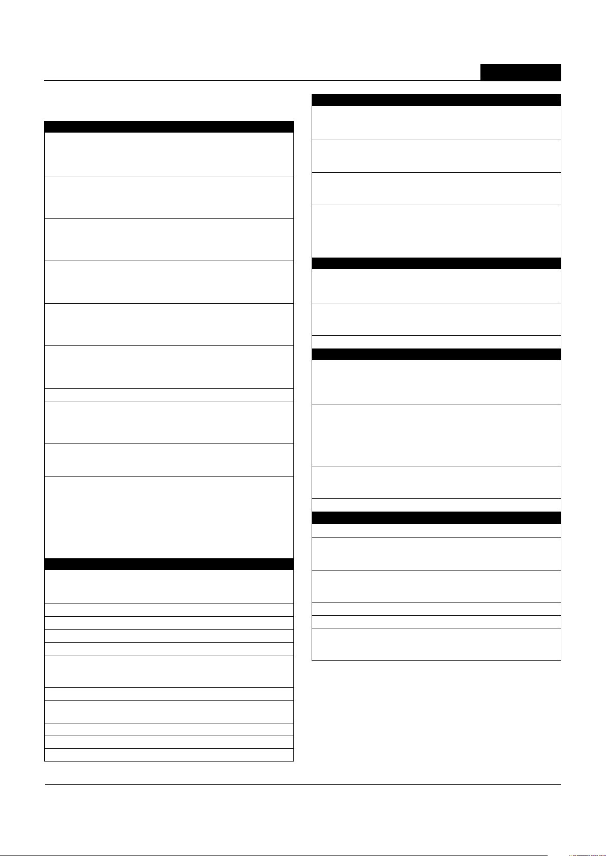
MEC ANICAL SPECIFI CATIONS
2
BOTTOM VIEW
1.800
(45.72)
0.10
(2.54)
2.00
(50.80)
8
5
6
7
0.40
(10.16)
0.200
(5.08)
0.400
(10.16)
0.100
(2.54)
1
2
4
METAL CASE
INSULATED BAS
E
0.040 ±0.002 DIA.
(1.016 ±0.051)
2.00
(50.80)
0.20 MIN
(5.08)
0.45
(11.43)
1.200
(30.48)
3 EQ. SP. @
0.400 (10.16)
I/O Connections
Pin Function P33
1 +Input
2 –Input
3 No Pin
4 On/Off Control
5 +5V Output
6 Output Return
7 +3.3V Output
8 Trim
Notes:
For "D12" and "D24" models
the case is connected to
pin 2 (–Input).
For "D48" models, the case
is connected to pin 1 (+Input).
Case C4
Page 3
BWR Models
33W, DUAL OUTPUT, MIXED-VOLTAGE DC/DC CONVERTERS
Performance/Functional Specifi cations
Typical @ TA = +25°C under nominal line voltage, balanced "full-load" conditions, unless noted. ➀
Input
Input Voltage Range:
D12 Models 10-18 Volts (12V nominal)
D24 Models 18-36 Volts (24V nominal)
D48 Models 36-75 Volts (48V nominal)
Overvoltage Shutdown:
➁
D12 Models 19-23 Volts (21V nominal)
D24 Models 37-42 Volts (40V nominal)
D48 Models 77-81 Volts (79V nominal)
Start-Up Threshold:
➁
D12 Models 9-10 Volts (9.3V nominal)
D24 Models 16.5-18 Volts (17V nominal)
D48 Models 34-36 Volts (35V nominal)
Undervoltage Shutdown:
➁
D12 Models 8.5-9.6 Volts (9.3V nominal)
D24 Models 16-17 Volts (16.5V nominal)
D48 Models 32.5-35 Volts (34V nominal)
Input Current:
Normal Operating Conditions See Ordering Guide
Standby Mode:
Off, OV, UV, Thermal Shutdown 10mA typical
Input Refl ected Ripple Current:
Source Impedance <0.1Ω, no external input fi ltering
D12 Models 200mAp-p (150mAp-p typical)
D24/D48 Models 250mAp-p (225mAp-p typical)
Internal Input Filter Type Pi (0.022µF - 4.7µH - 2.46µF)
Reverse-Polarity Protection:
➁
D12 Models 1 minute duration, 6A maximum
D24 Models 1 minute duration, 4A maximum
D48 Models 1 minute duration, 2A maximum
On/Off Control (Pin 4):
➁ ➂ ➃ ➅
D12, D24 & D48 Models On = open or 13V - +V
IN, IIN = 50µA max.
Off = 0-0.8V, I
IN = 1mA max.
Sync (Option, Pin 4): ➁ ➂ ➃
Input Threshold (Rising Edge Active) 1-2.7 Volts
Input Voltage Low 0-0.9 Volts
Input Voltage High 2.8-5 Volts
Input Resistance 35kΩ minimum
Output High Voltage (100µA load) 3.5-4.8 Volts
Output Drive Current 35mA
Input/Output Pulse Width 160-360nsec
Output
VOUT Accuracy
5V Output ±3% maximum
3.3V Output ±1.5% maximum
Minimum Loading Per Specifi cation No load, see Performance Specifi cations
Ripple/Noise (20MHz BW)
➁ ➄ See Ordering Guide
Line/Load Regulation
➁ See Ordering Guide
Effi ciency See Ordering Guide / Effi ciency Cur ves
Cross Regulation:
➁
5V Output (5V@0.6A, 3.3V@0.7-7A) ±6% maximum
3.3V Output (3.3V@0.7A, 5V@0.6-6A) ±0.5% maximum
Trim Range
➁ ±5%
Isolation Voltage:
Input-to-Output 1500Vdc minimum
Isolation Capacitance 470pF
Isolation Resistance 100MΩ
Temperature Coeffi cient ±0.02%/per°C
Output (continued)
Current Limit Inception: ➁
5V @ 95% VOUT (3.3V @ 0A) 7.6 -9.0 Amps
3.3V @ 98.5% V
OUT (5V @ 0A) 11.3 -12.7 Amps
Short Circuit Current:
➁
5V Output 5 Amps average, continuous
3.3V Output 6 Amps average, continuous
Overvoltage Protection:
➁ Magnetic feedback
5V Output 6.8 volts
3.3V Output 4.5Volts
Maximum Capacitive Loading
D12 Models 3.3V 1000µF
5V 470µF
D24, D48 Models 3.3V 2000µF
5V 1000µF
Dynamic Characteristics
Dynamic Load Response: ➁
5V (50-100% load step to 4% V
OUT) 300µsec maximum
3.3V (50-100% load step to 2.5% V
OUT) 300µsec maximum
Start-Up Time: ➁
V
IN to VOUT 20msec maximum
On/Off to V
OUT 15msec maximum
Switching Frequency 285kHz (±15kHz)
Environmental
MTBF ➆ Bellcore, ground fi xed, full power, +25°C
operating ambient temperature
D12 Models 1.3 million hours
D24/D48 Models 1.67 million hours
Operating Temperature (Ambient):
➁
Without Derating:
D12 Models –40 to +50°C
D24 Models –40 to +60°C
D48 Models –40 to +68°C
With Derating To +100°C (See Derating Curves)
Case Temperature:
Maximum Operational +100°C
For Thermal Shutdown
➁ +110°C minimum, +117°C maximum
Storage Temperature –40 to +120°C
Physical
Dimensions 2" x 2" x 0.45" (50.8 x 50.8 x 11.43mm)
Internal Case Connection:
D12/D24 Models –Input (Pin 2)
D48 Models +Input (Pin 1)
Case Material Corrosion resistant steel with
non-conductive, epoxy-based, black
enamel fi nish and plastic baseplate
Pin Material Brass, solder coated
Weight: 2.7 ounces (76.5 grams)
Primary to Secondary Insulation Level
D12/D24 Models Operational
D48 Models Basic
➀ Balanced "full-load" is 5V @ 3.3A/3.3V @ 5A. All models are specifi ed with external
1µF ceramic output capacitors.
➁ See Technical Notes/Graphs for details.
➂ Devices may be ordered with On/Off Control function or a Sync function.
See Part Number Suffi xes and Technical Notes for details.
➃ Applying a voltage to On/Off Control (pin 4) when no input power is applied to the
converter may cause permanent damage.
➄ Output noise may be further reduced with the installation of additional external output
capacitors. See Technical Notes.
➅ On/Off control is designed to be driven with open collector or by appropriate voltage
levels. Voltages must be referenced to the input return pin (–Input).
➆ Demonstrated MTBF available on request.
3
Page 4
33W, DUAL OUTPUT, MIXED-VOLTAGE DC/DC CONVERTERS
XWR Series
4
Absolute Maximum Ratings
Input Voltage:
Continuous: "D12" Models 23 Volts
"D24" Models 42 Volts
"D48" Models 81 Volts
Transient (100msec): "D12" Models 25 Volts
"D24" Models 50 Volts
"D48" Models 100 Volts
Input Reverse-Polarity Protection
➁ Input Current must be limited. 1 minute
duration. Fusing recommended.
"D12" Models 6 Amps
"D24" Models 4 Amps
"D48" Models 2 Amps
Output Current
➁ Current limited. Devices can withstand
an indefi nite output short circuit.
On/Off Control (Pin 4) Max. Voltages
Referenced to –Input (pin 2)
No Suffi x +V
IN
"S" Suffi x +5.7 Volts
Storage Temperature –40 to +120°C
Lead Temperature (Soldering, 10 sec.) +300°C
These are stress ratings. Exposure of devices to any of these conditions may adversely
affect long-term reliability. Proper operation under conditions other than those listed in the
Performance/Functional Specifi cations Table is not implied, nor recommended.
TECHNICAL NOTES
5V & 3.3V Regulation
The BWR 33 Watt Series converters are designed such that both the 5V and
3.3V outputs share a common regulation feedback control loop. Though the
feedback loop is infl uenced by both outputs, the 3.3 Volt output is dominant.
As a result, the 3.3 Volt regulation (1%) is superior to the 5 Volt regulation (4%).
The converters are specifi ed for load regulation of 10% to 100% loading and
for no-load to 100% loading. Operation below 10% of full load mandates
an increase in the regulation tolerance of ±0.5% for 3.3 Volt output and an
increase of ±1% for the 5 Volt output. A slight increase in switching noise
may also be observed for operation below 10% loading.
Operation with a full load on 3.3 Volt output and light to no load on 5 Volt
output is the most demanding for +5V regulation. Under such conditions the
internal "bleeder" circuit is activated to provide an internal load thereby keep-
ing regulation within the published specifi cations. The bleeder is activated
gradually so as not to cause any erratic behavior on the converters outputs. A
slight degradation in effi ciency will occur while this internal load is activated.
Filtering and Noise Reduction
The BWR 33 Watt Series Converters achieve their rated ripple and noise
specifi cations with the use of 1µF output capacitors. In critical applications,
input/output noise may be further reduced by installing additional external
I/O capacitors. Input capacitors should be selected for bulk capacitance,
low ESR and high rms-ripple-current ratings. Output capacitors should be
selected for low ESR and appropriate frequency response. All caps should
have appropriate voltage ratings and be located as close to the converter
as possible.
Start-Up Time
The V
IN to VOUT start-up time is the interval of time where the input voltage
crosses the turn-on threshold point, and the fully loaded output voltage enters
and remains within its specifi ed accuracy band. Actual measured times will
vary with input source impedance, external input/output capacitance, and the
slew rate of the input voltages. The BWR-5/6-3.3/7 Series implements a
soft start circuit that limits the duty cycle of the PWM controller at power up,
thereby limiting the Input Inrush current.
The On/Off Control to V
OUT start-up time assumes the converter has its
nominal input voltage applied but is turned off via the On/Off Control pin.
The specifi cation defi nes the interval between the time at which the converter
is turned on and the fully loaded output voltage enters and remains within
its specifi ed accuracy band. Similar to the V
IN to VOUT start-up, the On/Off
Control to V
OUT start-up time is also governed by the internal soft start
circuitry and external load capacitance.
Input Overvoltage/Undervoltage Shutdown and Start-Up Threshold
Under normal start-up conditions, devices will not begin to regulate until
the ramping-up input voltage exceeds the Start-Up Threshold Voltage (35V
for "D48" models). Once operating, devices will not turn off until the input
voltage drops below the Undervoltage Shutdown limit (34V for "D48" models).
Subsequent re-start will not occur until the input is brought back up to the
Start-Up Threshold. This built in hysteresis prevents any unstable on/off
situations from occurring at a single input voltage.
Input voltages exceeding the input overvoltage shutdown specifi cation listed
in the Performance/Functional Specifi cations will cause the device to shut-
down. A built-in hysteresis of 0.6 to 1.6 Volts for all models will not allow the
converter to restart until the input voltage is suffi ciently reduced.
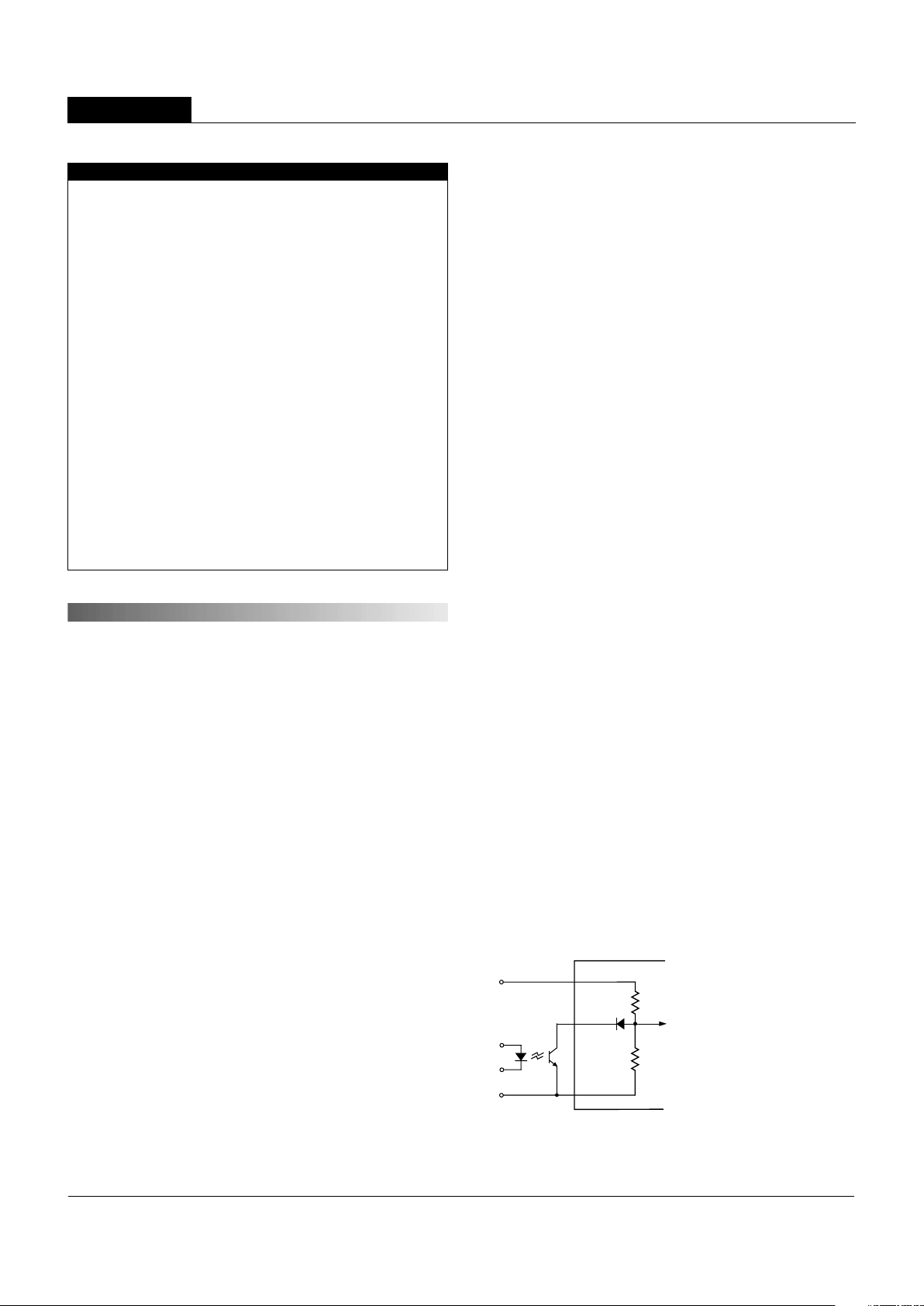
On/Off Control
The On/Off Control (pin 4) may be used for remote on/off operation. As
shown in Figure 1, the control pin is referenced to the –Input (pin 2) and will
be internally pulled to a high state. The standard BWR model (no suffi x) is
designed so that it is enabled when the control pin is left open and disabled
when the control pin is pulled low (less than +0.8V relative to –Input).
Dynamic control of the on/off function is best accomplished with a mechanical
relay or an open-collector/open-drain circuit (optically isolated if appropriate).
The drive circuit should be able to sink approximately 1 mA for logic low.
The on/off control function is designed such that the converter can be
disabled while the input power is ramping up, and then "released" once the
input has stabilized.
Figure 1. Internal Circuitry for No Suffi x Models
4
2
1
R
A
RB
+INPUT
–INPUT
ON/OFF
CONTROL
D12 RA = 34.8kΩ, RB = 6.83kΩ
D24 R
A = 100kΩ, RB = 9.74kΩ
D48 R
A = 100kΩ, RB = 4.53kΩ
Page 5

BWR Models
33W, DUAL OUTPUT, MIXED-VOLTAGE DC/DC CONVERTERS
5
Sync Function (Optional)
In critical applications employing multiple switching DC/DC converters, it
may be necessary to synchronize the switching of selected converters.
These BWR converters offer an optional Sync function ("S" suffi x) in place
of the On/Off Control on pin 4. The Sync pin will self confi gure as either
a slave or master, depending on the application. If the Sync pin detects
the appropriate input signal it will confi gure itself as a slave, if no signal is
detected it will generate master Sync pulses.
Synchronization of converters requires that the master switching frequency
exceed the slave frequency by a minimum of 60kHz. At the start of each
DC/DC converter switching cycle, an internally generated 160-360ns pulse
will be present at the Sync pin. If, however, the unit receives an external
Sync pulse, the DC/DC converter’s switching cycle will be reset, and a new
cycle initiated. Since the master frequency is higher than the slave’s switching
frequency, the slave cycles are always terminated prematurely, thereby never
allowing internal Synch pulses to be generated. The external signal’s rising
edge initiates the slave Sync process. External signals must adhere to min./
max. limits stated in Performance/Functional Specifi cations.
Operating these BWR converters at higher switching frequencies via the
external Sync function will result in a slight degradation of effi ciency.
Contact the DATEL for further information.
Current Limiting
When power demands from either output fall within 126% to 181% of the rated
output current, the DC/DC converter will go into a current limiting mode. In
this condition both output voltages will decrease proportionately with increases
in output current, thereby maintaining a somewhat constant power dissipa-
tion. This is commonly referred to as power limiting (see Figures 2a and
2b). Current limit inception is defi ned as the point where the full-power output
voltage falls below the specifi ed tolerance. If the load current being drawn
from the converter is signifi cant enough, the unit will go into a short circuit
condition. See "Short Circuit Condition."
Short Circuit Condition
When a converter is in current limit mode the output voltages will drop as the
output current demand increases (see fi gures 2a and 2b). If the output volt-
age drops too low, the magnetically coupled voltage used to develop primary
side voltages will also drop, thereby shutting down the PWM controller.
Following a time-out period of 5 to 15 milliseconds, the PWM will restart,
causing the output voltages to begin ramping to their appropriate values. If
the short-circuit condition persists, another shutdown cycle will be initiated.
This on/off cycling is referred to as "hiccup" mode. The hiccup cycling
reduces the average output current, thereby preventing internal temperatures
from rising to excessive levels. The BWR is capable of enduring an indefi nite
short circuit output condition.
Thermal Shutdown
These BWR converters are equipped with Thermal Shutdown Circuitry. If
the internal temperature of the DC/DC converter rises above the designed
operating temperature, a precision temperature sensor will power down the
unit. When the internal temperature decreases below the threshold of the
temperature sensor the unit will self start.
Output Overvoltage Protection
Both output voltages are monitored for an overvoltage condition via magnetic
coupling to the primary side. If either output voltage should rise to a level
which could be damaging to the load circuitry, the sensing circuitry will power
down the PWM controller causing the output voltages to decrease. Following
a time-out of 5 to 15 milliseconds the PWM will restart, causing the output
voltages to ramp to their appropriate values. If the fault condition persists,
and the output voltages again climb to excessive levels, the overvoltage
circuitry will initiate another shutdown cycle. This on/off cycling is referred
to as "hiccup" mode.
Figure 2a. Current Limiting Characteristics for 3.3V Output
Figure 2b. Current Limiting Characteristics for 5V Output
4
3
2
1
0
0 2 4 6 8 101214
3.3 V
OUT Average Ouput Current (Amps)
Typical Current Limiting Characteristics for 3.3V Output
(5V Output @ 600mA)
Ouput Voltages (Volts)
VIN NOM, VIN LO All Models
VIN HI D12, D24 Models
V
IN HI
D48 Models
5
4.5
4
3.5
3
2.5
2
1.5
1
0.5
0
0123456789
5 V
OUT Average Ouput Current (Amps)
Ouput Voltages (Volts)
VIN NOM, VIN LO
All Models
V
IN HI D12, D24
Models
V
IN HI
D48 Models
Typical Current Limiting Characteristics for 5V Output
(3.3V Output @ 700mA)
Page 6

33W, DUAL OUTPUT, MIXED-VOLTAGE DC/DC CONVERTERS
XWR Series
Isolation / Case Connection
The BWR 33 Watt Series’ 5V and 3.3V outputs (pins 5 & 7) and return (pin
6) are isolated from the +V
IN and –VIN inputs (pins 1 & 2) via a transformer
and an opto-coupled transistor. Case connections are made internal to the
DC/DC converter. "D12 & D24" cases are connected to –Input (pin 2), "D48"
to +Input (pin 1).
Input Reverse-Polarity Protection
Upon applying a reverse-polarity voltage to the DC/DC converter, an internal
diode will be forward biased, drawing excessive current from the power
source. Therefore, it is required that the input current be limited be either an
appropriately rated input fuse or a current limited power source.
Input Fusing
Certain applications and/or safety agencies may require the installation of
fuses at the inputs of power conversion components. Fuses should also
be used if the possibility of a sustained, non-current-limited, input-voltage
polarity reversal exists. For DATEL BWR 33 Watt Series Converters, slow
blow fuses are recommended with values no greater than the following.
V
IN Range Fuse Value
"D12" Models 6 Amps
"D24" Models 4 Amps
"D48" Models 2 Amps
It is recommended that fuses be installed in the +Input line.
Trimming Output Voltages
These BWR converters have a trim capability (pin 8) that allow users to
adjust the output voltages ±5%. A trim adjustment will cause an equal
percentage of change in both outputs. Adjustments to the output voltages
can be accomplished via a trim pot Figure 3 or a single fi xed resistor as
shown in Figures 4 and 5. A single fi xed resistor can increase or decrease
the output voltage depending on its connection. Fixed resistors should
be metal-fi lm types with absolute TCR’s less than 100ppm/°C to minimize
sensitivity to changes in temperature.
A single resistor connected from the Trim Pin (pin 8) the +3.3V Output (pin
7), see Figure 4, will decrease the output voltages. A resistor connected
from the Trim Pin (pin 8) to Output Return (pin 6) will increase the output
voltages.
Table 1 shows the typical Trim Resistor values for output voltage changes
of 1 through 5%.
Trim adjustment greater than 5% can have an adverse affect on the convert-
er’s performance and is not recommended.
20kΩ
5-22
Turns
+INPUT
+5V OUTPUT
+3.3V OUTPUT
TRIM
OUTPUT
RETURN
–INPUT
ON/OFF
CONTROL
1
2
4
5
8
6
+5V LOAD
+3.3V LOAD
7
+INPUT
+5V OUTPUT
+3.3V OUTPUT
TRIM
OUTPUT
RETURN
–INPUT
ON/OFF
CONTROL
1
2
4
5
8
6
+5V LOAD
+3.3V LOAD
R TRIM
DOWN
7
+INPUT
+5V OUTPUT
+3.3V OUTPUT
TRIM
OUTPUT
RETURN
–INPUT
ON/OFF
CONTROL
1
2
4
5
8
6
+5V LOAD
+3.3V LOAD
R TRIM
UP
7
Figure 5. Increase Output Voltage Trim Connections
Using A Fixed Resistor
Figure 3. Trim Connections using a Trimpot
Figure 4. Decrease Output Voltage Trim Connections
Using A Fixed Resistor
Trim Down Trim Up
0% – –
1% 153k 178.9k
2% 79.1k 67k
3% 50k 37.5k
4% 34.5k 23.9k
5% 24.8k 16k
Table 1. Percentage of Output Voltage Change vs Trim Resistor Value (Ohms)
Trim Down
–13
DOWN
VO – 1.275
R
T (kΩ) =
–0.242
je
0.624 – 0.04VO
1
L
N
O
Q
VO =
R
T + 13
DOWN
je
+ 0.282
1
RT + 13
DOWN
je
0.993 +
1.275
VO =
4.523
R
T + 13
UP
–13
+3.308
UP
1
0.190(V
O – 1.275) + 0.031VO – 0.489
j
e
RT (kΩ) =
Trim Up
Note: Accuracy of adjustment is subject to the tolerances of resistor
values, reference accuracy and factory-adjusted output accuracy.
V
O = desired output voltage.
6
Page 7

BWR Models
33W, DUAL OUTPUT, MIXED-VOLTAGE DC/DC CONVERTERS
D12 Model D12, D24, D48 Models
Typical Performance Curves
7
D24 Model
D48 Model
Input Ripple Current (VIN = 18V, 5V @ 3A, 3.3V@ 4.5A,
no external filtering, source impedance <0.1Ω.)
50mA/div
1µsec/div
Input Ripple Current (VIN = 36V, 5V @ 3A, 3.3V@ 4.5A,
no external filtering, source impedance <0.1Ω.)
50mA/div
1µsec/div
Input Ripple Current (VIN = 75V, 5V @ 3A, 3.3V@ 4.5A,
no external filtering, source impedance <0.1Ω.)
50mA/div
1µsec/div
Output Ripple and Noise (PARD)
(
VIN = nominal, 5V@3A, 3.3V @ 4.5A, external 1µF output capacitors.)
3.3V Output
Ripple/Noise
50mV/div
20MHz BW
5V Output
Ripple/Noise
50mV/div
20MHz BW
1µsec/div
Output Ripple and Noise (PARD)
(VIN = nominal, 5V@0A, 3.3V @ 7A, external 1µF output capacitors.)
3.3V Output
Ripple/Noise
50mV/div
20MHz BW
5V Output
Ripple/Noise
50mV/div
20MHz BW
1µsec/div
Output Ripple and Noise (PARD)
(VIN = nominal, 5V@ 6A, 3.3V @ 0A, external 1µF output capacitors.)
3.3V Output
Ripple/Noise
50mV/div
20MHz BW
5V Output
Ripple/Noise
50mV/div
20MHz BW
1µsec/div
Page 8

33W, DUAL OUTPUT, MIXED-VOLTAGE DC/DC CONVERTERS
XWR Series
8
D12, D24, D48 Models
Typical Performance Curves
D12, D24, D48 Models
5V Output Half-Load to Full-Load Transient Response
(VIN = nominal, 3.3V@ 700mA, external 1µF output capacitors.)
5V Output
100mV/div
Output
Current
2A/div
100µsec/div
6A
3A
5V Output Full-Load to Half-Load Transient Response
(VIN = nominal, 3.3V@ 700mA, external 1µF output capacitors.)
5V Output
100mV/div
Output
Current
2A/div
100µsec/div
6A
3A
3.3V Output Half-Load to Full-Load Transient Response
(VIN = nominal, 5V@ 600mA, external 1µF output capacitors.)
3.3V Output
100mV/div
Output
Current
2A/div
100µsec/div
7A
3.5A
3.3V Output Full-Load to Half-Load Transient Response
(VIN = nominal, 5V@ 600mA, external 1µF output capacitors.)
3.3V Output
100mV/div
Output
Current
2A/div
100µsec/div
3.5A
7A
Percentage of Change on 3.3 VOUT (%)
5 Volt Output Current (Amps)
Cross Regulation Effects on +3.3VOUT
(Reference Point 5V @ 3.9A, 3.3V @ 4A)
0.8
0.6
0.4
0.2
0
–0.2
–0.4
–0.6
0123456
3.3V @ 2A
3.3V @ 4A
3.3V @ 7A
3.3V @ 0A
3.3V @ 6A
Percentage of Change in +5 VOUT (%)
3.3 Volt Current (Amps)
Cross Regulation Effects On +5VOUT
(Reference Point 5V @ 4A, 3.3V @ 3.9A)
4.0
3.0
2.0
1.0
0
–1.0
–2.0
–3.0
–4.0
0123 4567
5V @ 0A
5V @ 2A
5V @ 4A
5V @ 6A
Page 9

BWR Models
33W, DUAL OUTPUT, MIXED-VOLTAGE DC/DC CONVERTERS
9
D12, D24, D48 Models
Typical Performance Curves
Start-Up from VIN
(VIN = nominal, 5V@ 3A, 3.3V @ 4.5A, external 1µF output capacitors.)
2msec/div
3.3V
Output
2V/div
5V
Output
2V/div
V
IN
Start-Up from Remote On/Off Control
(VIN = nominal, 5V@ 3A, 3.3V @ 4.5A, external 1µF output capacitors.)
2msec/div
3.3V
Output
2V/div
5V
Output
2V/div
Remote
On/Off
(Pin 4)
D12, D24, D48 Models
D12 Models D24, D48 Models
90
85
80
75
70
65
60
D12 - 3.3 Volt Output Efficiency vs. Line and Load
(+5V @ 600mA)
0.70 1.40 2.10 2.80 3.50 4.20 4.90 5.60 6.30 7.00
+3.3V Output Current (Amps)
Efficiency (%)
V
IN
= 18V
V
IN
= 12V
V
IN
= 10V
90
85
80
75
70
65
60
D12 - 5 Volt Output Efficiency vs. Line and Load
(+3.3V @ 700mA)
0.60 1.20 1.80 2.40 3.00 3.60 4.20 4.80 5.40 6.00
+5V Output Current (Amps)
Efficiency (%)
V
IN
= 10V
V
IN
= 18V
V
IN
= 12V
95
90
85
80
75
70
65
60
55
50
D24/D48 - 3.3 Volt Output Efficiency vs. Line and Load
(+5V @ 600mA)
0 0.78 1.56 2.33 3.11 3.89 4.67 5.44 6.22 7.00
+3.3V Output Current (Amps)
Efficiency (%)
V
IN
= MAX
V
IN
= NOMINAL
V
IN
= MIN
95
90
85
80
75
70
65
60
55
50
D24/D48 - 5 Volt Output Efficiency vs. Line and Load
(+3.3V @ 700mA)
0 0.67 1.33 2.00 2.67 3.33 4.00 4.67 5.33 6.00
+5V Output Current (Amps)
Efficiency (%)
V
IN
= MAX
V
IN
= NOMINAL
V
IN
= MIN
Page 10

33W, DUAL OUTPUT, MIXED-VOLTAGE DC/DC CONVERTERS
XWR Series
Output Power (Watts)
Ambient Temperature (˚C)
–400 15202530354045505560657075 80 85 90 95 100
35
30
25
20
15
10
5
0
Loading (5V @ 1.98A, 3.3V @ 7A)
Loading (5V @ 3.74A, 3.3V @ 4.33A)
Loading (5V @ 5.1A, 3.3V @ 2.33A)
Loading (5V @ 6A, 3.3V @ 0.7A)
Output Power vs. Ambient Temperature
V
IN = 12V, Natural Convection Air flow
Output Power (Watts)
Ambient Temperature (˚C)
–400 15202530354045505560657075 80 85 90 95 100
35
30
25
20
15
10
5
0
Loading (5V @ 1.98A, 3.3V @ 7A)
Loading (5V @ 3.74A, 3.3V @ 4.33A)
Loading (5V @ 5.1A, 3.3V @ 2.33A)
Loading (5V @ 6A, 3.3V @ 0.7A)
Output Power vs. Ambient Temperature
V
IN = 18V, Natural Convection Air flow
Output Power (Watts)
Ambient Temperature (˚C)
–400 15202530354045505560657075 80 85 90 95 100
35
30
25
20
15
10
5
0
Natural Convection Air FlowLoading
150lfm Air Flow
300lfm Air Flow
Output Power vs. Ambient Temperature
V
IN = Nominal, 5V @ 3.74A/3.3V @ 4.33A
10
Temperature Derating and Electrical Performace Curves
D24 ModelsD12 Models
Output Power (Watts)
Ambient Temperature (˚C)
–400 15202530354045505560657075 80 85 90 95 100
35
30
25
20
15
10
5
0
Loading (5V @ 1.98A, 3.3V @ 7A)
Loading (5V @ 3.74A, 3.3V @ 4.33A)
Loading (5V @ 5.1A, 3.3V @ 2.3A)
Loading (5V @ 6A, 3.3V @ 0.7A)
Output Power vs. Ambient Temperature
V
IN = 24V, Natural Convection Air flow
Output Power (Watts)
Ambient Temperature (˚C)
–400 15202530354045505560657075 80 85 90 95 100
35
30
25
20
15
10
5
0
Loading (5V @ 1.98A, 3.3V @ 7A)
Loading (5V @ 3.74A, 3.3V @ 4.33A)
Loading (5V @ 5.1A, 3.3V @ 2.3A)
Loading (5V @ 6A, 3.3V @ 0.7A)
Output Power vs. Ambient Temperature
V
IN = 36V, Natural Convection Air flow
Output Power (Watts)
Ambient Temperature (˚C)
–400 15202530354045505560657075 80 85 90 95 100
35
30
25
20
15
10
5
0
Natural Convection Air FlowLoading
150lfm Air Flow
300lfm Air Flow
Output Power vs. Ambient Temperature
V
IN = Nominal, 5V @ 3.74A/3.3V @ 4.33A
Page 11

BWR Models
33W, DUAL OUTPUT, MIXED-VOLTAGE DC/DC CONVERTERS
DA TEL mak es no representation that the use of its products in the circuits described herein, or the use of other technical information contained herein, will not infringe upon existing or future patent rights. The descriptions contained herein do
not imply the granting of licenses to make, use, or sell equipment constructed in accordance therewith. Specifi cations are subject to change without notice. The DATEL logo is a registered DATEL, Inc. trademark.
DATEL (UK) LTD. Tadley, England Tel: (01256)-880444
DATEL S.A.R.L. Montigny Le Bretonneux, France Tel: 01-34-60-01-01
DATEL GmbH München, Germany Tel: 89-544334-0
DATEL KK Tokyo, Japan Tel: 3-3779-1031, Osaka Tel: 6-6354-2025
DATEL, Inc. 11 Cabot Boulevard, Mansfi eld, MA 02048-1151
Tel: (508) 339-3000 (800) 233-2765 Fax: (508) 339-6356
Internet: www.datel.com Email: sales@datel.com
ISO 9001 REGISTERED
INNOVATION and EX C ELL E N C
E
®
®
DS-0481A 1/01
11
Temperature Derating and Electrical Performace Curves
D48 Models D48 Models
Output Power (Watts)
Ambient Temperature (˚C)
–400 15202530354045505560657075 80 85 90 95 100
35
30
25
20
15
10
5
0
Loading (5V @ 1.98A, 3.3V @ 7A)
Loading (5V @ 3.74A, 3.3V @ 4.33A)
Loading (5V @ 5.1A, 3.3V @ 2.33A)
Loading (5V @ 6A, 3.3V @ 0.7A)
Output Power vs. Ambient Temperature
V
IN = 48V, Natural Convection Air flow
Output Power (Watts)
Ambient Temperature (˚C)
–400 15202530354045505560657075 80 85 90 95 100
35
30
25
20
15
10
5
0
Loading (5V @ 1.98A, 3.3V @ 7A)
Loading (5V @ 3.74A, 3.3V @ 4.33A)
Loading (5V @ 5.1A, 3.3V @ 2.33A)
Loading (5V @ 6A, 3.3V @ 0.7A)
Output Power vs. Ambient Temperature
V
IN = 75V, Natural Convection Air flow
Output Power (Watts)
Ambient Temperature (˚C)
–400 15202530354045505560657075 80 85 90 95 100
35
30
25
20
15
10
5
0
Natural Convection Air FlowLoading
150lfm Air Flow
300lfm Air Flow
Output Power vs. Ambient Temperature
V
IN = Nominal, 5V @ 3.74A/3.3V @ 4.33A
 Loading...