

Datasheet BWR-12-125-D12, BWR-12-105-D5, BWR-15-85-D5, BWR-15-100-D48, BWR-5-250-D48 Datasheet (DATEL)
...Page 1
DATEL, Inc., 1 1 Cabot Boulevard, Mansfield, MA 02048 (U.S.A.) · Tel: (508)339-3000, (800)233-2765 Fax: (508)339-6356 · Email: datellit@mcimail.com
Packaged in industry-standard DIP’s, the 3 Watt dual-output models of DA TEL’ s XWR
Series DC/DC converters are fully regulated (±0.5% max. line, ±1% max. load), fully
isolated (1000Vdc minimum), extremely efficient (as high as 78% guaranteed) building
blocks providing true component-like flexibility and convenience to designers of modern
distributed power systems.
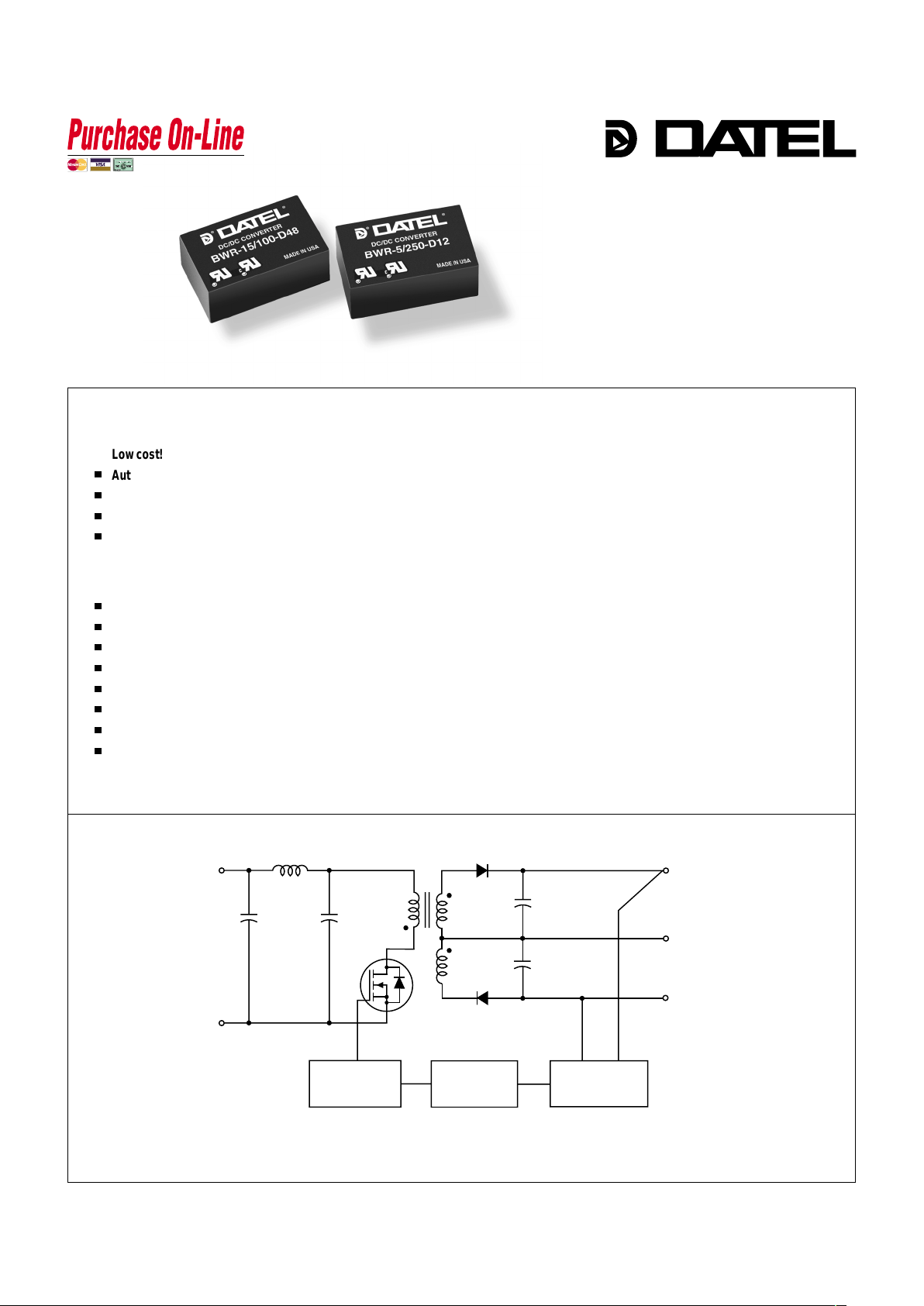
Exploiting high-frequency (170-200kHz), flyback topologies and contemporary,
highly automated, SMT assembly techniques, BWR Model DC/DC’s have enough room
to include input (pi type) and output filters within their package. Offering true "plug-andplay" convenience, these power converters require no external components. They
operate over the full –25 to +75°C temperature range with no output power derating.
Output voltages are either ±5, ±12 or ±15 Volts. Input voltage ranges are either
4.5-9V ("D5" models), 9-18V ("D12" models) or an ultra-wide 18-72V ("D48" models).
Transient response time is a quick 200µsec.
These extremely rugged modules are fully encapsulated with a thermally conductive
potting compound. They are moisture and vibration resistant and have established a
reputation for outstanding MTBF . For telecommunication, computer and other EMIsensitive applications, these DIP-packaged DC/DC converters offer full EMI/EMC
characterization data.
Industry-standard pinouts make DATEL ’s BWR Model 3W DC/DC’s ideal replacements for other more costly, less reliable power converters. Similarly, they are excellent
choices for new design-ins in systems demanding small size, low cost and high reliability.
Figure 1. Simplified Schematic
Dual Output
BWR Models
Features
Low-Cost, DIP-Packaged
3 Watt, DC/DC Converters
INNOVATION and EX C ELL E N C E
®
®
■
n
n
n
n
n
n
n
n
n
n
n
n
Low cost!
Automated, SMT-on-pcb construction
No external components required
±5, ±12 or ±15 V olt outputs
Choice of 3 input voltage ranges:
4.5-9 Volts
9-18 Volts
18-72 Volts
1.25" x 0.8" x 0.45" DIP form factor
Industry-standard package and pinout
Fully isolated, 1000Vdc guaranteed
Guaranteed efficiencies to 78%
–25 to +75°C operation with no derating
UL 1950, CSA 22.2 No. 234 and IEC 950
EMI/EMC characterized
Modifications and customs for OEM’s
+V
IN
–
V
IN
+V
OUT
–V
OUT
COMMON
REFERENCE &
ERROR AMP
OPTO
ISOLATION
PWM
CONTROLLER
www.datel.co
m
Page 2
XWR Series
3W, DUAL OUTPUT DC/DC CONVERTERS
2
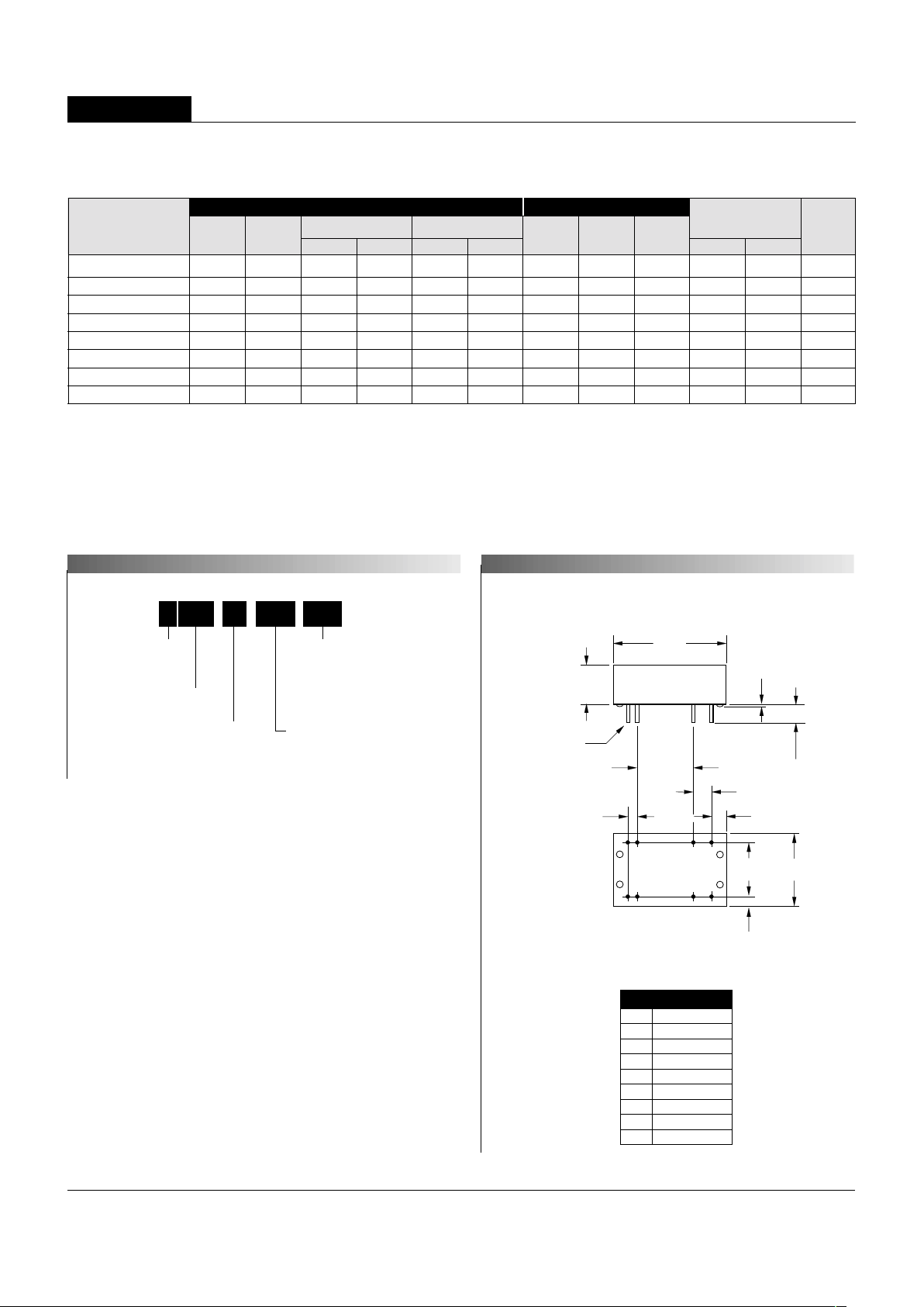
Mechanical Specifications
Pin
1
2
3
4
5
6
7
8
I/O Connectiions
Function P2
+Input
+Input
–Input
–Input
Common
+Output
Common
–Output
0.020 ±0.002 DIA.
(0.508 ±0.051)
0.15 MIN
(3.81)
0.45
(11.43)
1.25
(31.75)
0.200
(5.08)
0.10
(2.54)
0.80
(20.32)
0.600
(15.24)
0.100
(2.54)
0.18
(4.57)
STANDOFFS
0.025
(0.64)
0.600
(15.24)
BOTTOM VIEW
1
2
34
56
87
PLASTIC CASE WITH AN INSULATED BASE
Case C1
BWR-5/250-D12 ±5 ±250 75 120 ±0.5% ±1.0% 12 9-18 35/278 75% 77% C1, P2
BWR-5/250-D48 ±5 ±250 75 120 ±0.5% ±1.0% 48 18-72 10/76 75% 77% C1, P2
BWR-12/105-D5 ±12 ±105 75 150 ±0.5% ±1.0% 5 4.5-9 75/727 70% 72% C1, P2
BWR-12/125-D12 ±12 ±125 75 150 ±0.5% ±1.0% 12 9-18 35/346 73% 75% C1, P2
BWR-12/125-D48 ±12 ±125 75 150 ±0.5% ±1.0% 48 18-72 10/81 78% 80% C1, P2
BWR-15/85-D5 ±1 5 ±85 75 150 ±0.5% ±0.5% 5 4.5-9 100/736 70% 72% C1, P2
BWR-15/100-D12 ±15 ±100 75 150 ±0.5% ±1.0% 12 9-18 35/346 73% 75% C1, P2
BWR-15/100-D48 ±15 ±100 75 150 ±0.5% ±1.0% 48 18-72 10/81 78% 80% C1, P2
Performance Specifications and Ordering Guide
R/N (mVp-p)
➁
Load
VOUT
(Volts)
Output
Package
(Case,
Pinout)
Efficiency
Regulation (Max.)
➂
Line
VIN Nom.
(Volts)
Range
(Volts)
Model
Input
IIN ➃
(mA)
➀
Max.
Typ.
Typ.
Min.
IOUT
(mA,Max.)
PART NUMBER STRUCTURE
MECHANICAL SPECIFICATIONS
Nominal Output V oltages:
±5, ±12 or ±15 Volts
Maximum Output Current
in mA from each output
Input Voltage Range:
D5 = 4.5-9 Volts (5V nominal)
D12 = 9-18 Volts (12V nominal)
D48 = 18-72 Volts (48V nominal)
Wide Range Input
Output Configuration:
B = Bipolar
15B WR 100 D48-/ -
➀
Typical at TA = +25°C under nominal line voltage and full-load conditions unless otherwise noted.
➁
Ripple/Noise (R/N) measured over a 20MHz bandwidth.
➂
Balanced loads, 10% to 100% load.
➃
Nominal line voltage, no-load/full-load conditions.
Page 3

BWR Models
3W, DUAL OUTPUT DC/DC CONVERTERS
3
Input Voltage:
"D5" Models 12 Volts
"D12" Models 20 Volts
"D48" Models 80 Volts
Input Reverse-Polarity Protection Current must be <2A. Brief duration
only. Fusing recommended.
Output Overvoltage Protection None
Output Current Current limited. Max. current and
short-circuit duration are model
dependent. "D12" and "D48" models
can withstand sustained output short
circuits.
Storage Temperature –40 to +100°C
Lead Temperature (soldering, 10 sec.) +300°C
Performance/Functional Specifications
Typical @ TA = +25°C under nominal line voltage and full-load conditions, unless noted.
➀
Input
Input Voltage Range:
"D5" Models 4.5-9 Volts (5V nominal)
"D12" Models 9-18 Volts (12V nominal)
"D48" Models 18-72 Volts (48V nominal)
Input Current See Ordering Guide
Input Filter Type
➁
Pi
Reverse-Polarity Protection Yes (Instantaneous, 2A maximum)
Output
VOUT Accuracy (50% load) ±1%, maximum
Temperature Coefficient ±0.02% per °C
Ripple/Noise (20MHz BW)
➁
See Ordering Guide
Line/Load Regulation See Ordering Guide
Efficiency See Ordering Guide
Isolation Voltage
➂
1000Vdc, minimum
Current Limiting:
"D5" Models Power-limiting technique, auto-recovery
"D12" and "D48" Models Hiccup technique, auto-recovery
Dynamic Characteristics
Transient Response (50% load step) 200µsec to ±1% of final value
Switching Frequency:
"D5" Models 200kHz
"D12" and "D48" Models 170kHz
Environmental
Operating Temperature
➃
(Ambient, no derating) –25 to +75°C
Storage Temperature –40 to +100°C
Physical
Dimensions 1.25" x 0.8" x 0.45" (31.8 x 20.3 x 11.4mm)
Case Material Diallyl phthalate, UL94V-0-rated
Pin Material Brass, solder coated
Weight 0.5 ounces (14.2 grams)
➀
These power converters require a minimum 10% loading to maintain specified regulation.
Operation under no-load conditions will not damage these devices; however they may not
meet all listed specifications.
➁
Application-specific internal input/output filtering can be recommended and perhaps added
internally upon request. Contact DATEL Applications Engineering for details.
➂
Devices can be screened or modified for higher guaranteed isolation voltages.
Contact DATEL Applications Engineering for details.
➃
Devices can be warranted or screened for lower-temperature operation.
Contact DATEL Applications Engineering for details. See DA TEL's new BST 3W Models
for guaranteed operation to –40°C.
These are stress ratings. Exposure of devices to any of these conditions may adversely
affect long-term reliability. Proper operation under conditions other than those listed in the
Performance/Functional Specifications T able is not implied.
Absolute Maximum Ratings
TECHNICAL NOTES
Floating Outputs
Since these are isolated DC/DC converters, their outputs are "floating." Any
BWR model may be configured to produce an output of 10V , 24V or 30V (for
±5V , ±12V or ±15V models, respectively) by applying the load across the
+Output and –Output pins (pins 6 and 8), with either output grounded. The
Common (pins 5 and 7) should be left open. Minimum 20% loading is
recommended under these conditions.
Filtering and Noise Reduction
All BWR 3 Watt DC/DC Converters achieve their rated ripple and noise
specifications without the use of external input/output capacitors. In critical
applications, input/output ripple and noise may be further reduced by installing
electrolytic capacitors across the input terminals and/or low-ESR tantalum or
electrolytic capacitors across the output terminals. Output capacitors should be
connected between their respective output pin (pin 6 or 8) and Common (pins 5
and 7) as shown in Figure 2. The caps should be located as close to the power
converters as possible. T ypical values are listed in the tables below. In many
applications, using values greater than those listed will yield better results.
To Reduce Input Ripple
"D5" Models 47µF , 15V
"D12" Models 10µF, 35V
"D48" Models 4.7µF, 100V
To Reduce Output Ripple
±5V Outputs 47µF, 10V, Low ESR
±12/15V Outputs 22µF, 20V, Low ESR
In critical, space-sensitive applications, DA TEL may be able to tailor the internal
input/output filtering of these units to meet your specific requirements. Contact
our Applications Engineering Group for additional details.
Page 4

If you’re designing with EMC in mind, note that all of DA TEL’s BWR 3 Watt
DC/DC Converters have been characterized for radiated and conducted emissions
in our new EMI/EMC laboratory. T esting is conducted in an EMCO 5305 GTEM
test cell utilizing EMCO automated EMC test software. Radiated emissions are
tested to the limits of FCC Part 15, Class B and CISPR 22 (EN 55022), Class B.
Correlation to other specifications can be supplied upon request. Radiated
emissions plots to FCC and CISPR 22 for model BWR-5/250-D12 appear below.
Published EMC test reports are available for each model number. Contact
DATEL’s Applications Engineering Department for more details.
DATEL’s world-class design, development and manufacturing team stands
ready to work with you to deliver the exact power converter you need for your
demanding, large volume, OEM applications. And ... we’ll do it on time and
within budget!
Our experienced applications and design staffs; quick-turn prototype capability;
highly automated, SMT assembly facilities; and in-line SPC quality-control
techniques combine to give us the unique ability to design and deliver any
quantity of power converters to the highest standards of quality and reliability.
We have compiled a large library of DC/DC designs that are currently used in a
variety of telecom, medical, computer, railway , aerospace and industrial
applications. We may already have the converter you need.
Contact us. Our goal is to provide you the highest-quality, most costeffective power converters available.
DS0317 8/99
EMI RADIATED EMISSIONS
INNOVATION and EX C ELL E N C
E
®
®
DATEL makes no representation that the use of its products in the circuits described herein, or the use of other technical information contained herein, will not infringe upon existing or future patent rights. The descriptions contained herein
do not imply the granting of licenses to make, use, or sell equipment constructed in accordance therewith. Specifications are subject to change without notice. The DATEL logo is a registered DATEL, Inc. trademark.
DATEL (UK) L TD. Tadley, England T el: (01256)-880444
DATEL S.A.R.L. Montigny Le Bretonneux, France Tel: 01-34-60-01-01
DATEL GmbH München, Germany Tel: 89-544334-0
DATEL KK Tokyo, Japan T el: 3-3779-1031, Osaka Tel: 6-354-2025
DATEL, Inc. 11 Cabot Boulevard, Mansfield, MA 02048-1151
Tel: (508) 339-3000 (800) 233-2765 Fax: (508) 339-6356
Internet: www.datel.com Email: sales@datel.com
Data Sheet Fax Back: (508) 261-2857
CUSTOM CAPABILITIES
XWR Series
3W, DUAL OUTPUT DC/DC CONVERTERS
80
70
60
50
40
30
20
10
0
–10
–20
Frequency (MHz)
100
1000
Radiated Emissions
FCC Class B Limit
BWR-5/250-D12 Radiated Emissions
FCC Part 15 Class B, 3 Meters
Converter Output = ±5Vdc @ ±203mA
Radiated Emissions (dBµV/M)
BWR-5/250-D12 Radiated Emissions
EN 55022 Class B, 10 Meters
Converter Output = ±5Vdc @ ±203mA
80
70
60
50
40
30
20
10
0
–10
–20
Frequency (MHz
)
100
1000
Radiated Emissions
EN 55022 Class B Limit
Radiated Emissions (dBµV/M)
Input Fusing
Certain applications and/or safety agencies may require the installation of fuses
at the inputs of power conversion components. For DATE L BWR 3 W att
DC/DC Converters, you should use slow-blow type fuses with values
no greater than the following:
V
IN Range Fuse Value
"D5" 1.5A
"D12" 1A
"D48" 0.5A
Figure 2. Using External Capacitors to Reduce
Input/Output Ripple/Noise
1, 2
3, 4
6
8
5, 7
C
IN
C
OUT
C
OUT
+
+
+
–OUTPUT
+INPUT
–INPUT
+OUTPUT
COMMON
ISO-9001 REGISTERED
 Loading...