

Datasheet BQ2164MODULE, BQ2164B-KT, BQ2164B-010, BQ2164B-009, BQ2164B-007 Datasheet (Texas Instruments)
Page 1
Features
ä
Complete bq2004/bq2014 battery management
solution for NiCd or NiMH pack
ä
Accurate battery state-of-charge monitoring
ä
Reliable fast charge termination
ä
Automatic full capacity calibration
ä
Battery information available over a single-wire
bi-directional serial port
ä
Nominal capacity, cell chemistry, and charge control
parameters pre-configured
ä
Compact size for battery pack integration
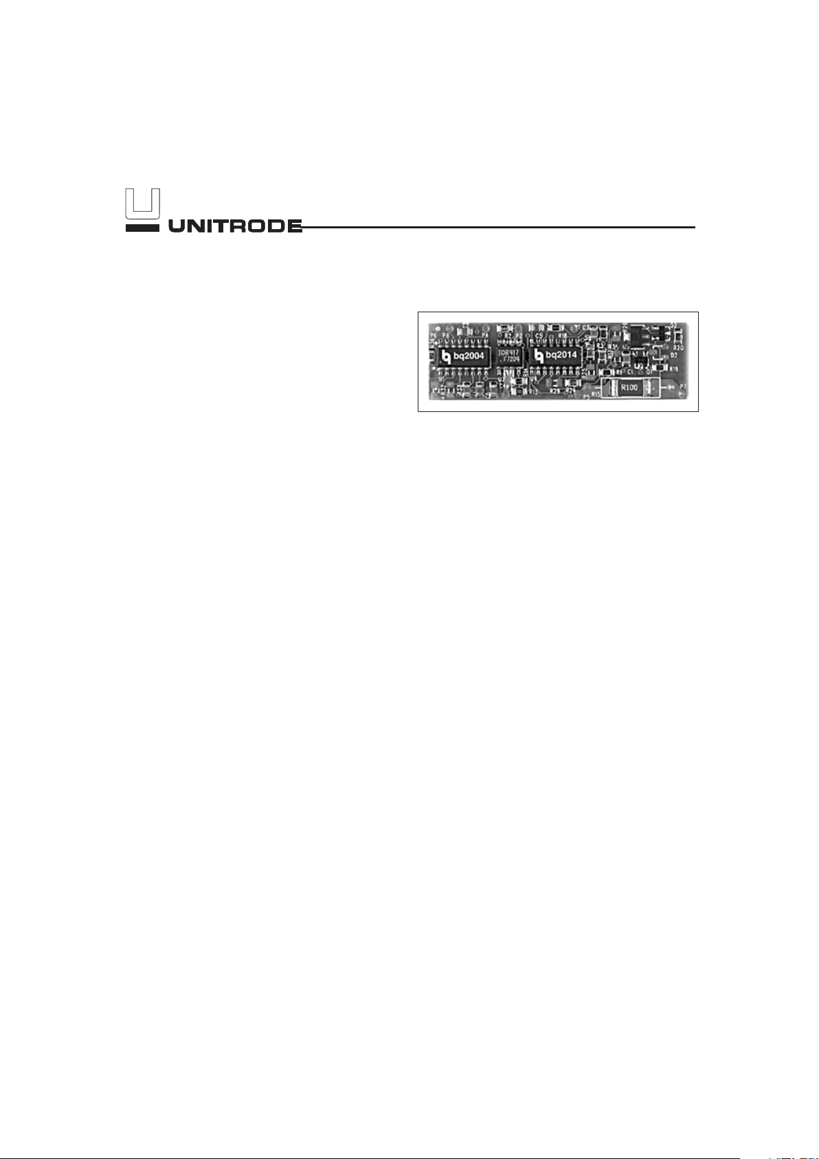
General Description
The bq2164 Gas Gauge Module provides a complete and
compact battery management solution for NiCd and NiMH
battery packs. Designed for battery pack integration, the
bq2164 combines the bq2014 Gas Gauge IC with the
bq2004 Fast-Charge IC on a small printed circuit board.
The board includes all the necessary components to accurately monitor the capacity and reliably terminate fast
charge of 5 to 10 series cells.
The gas gauge IC uses the onboard sense resistor to track
charge and discharge activity of the battery pack. The fast
charge IC gates a current-limited or constant-current charg
ing supply connected to PACK+. Charging termination is
based on∆T/∆tor-∆V/PVD, maximum temperature, time,
and voltage. The bq2004 signals charge completion to the
bq2014 to indicate full capacity. The charge complete signal
to the gas gauge eliminates the need to fully cycle the bat
tery pack to initially calibrate full pack capacity.
Contacts are provided on the bq2164 for direct connec
tion to the battery stack (BAT+, BAT-), the gas gauge's
communications port (DQ), and the thermistor
(THERM+, THERM). The thermistor is required for
temperature fast charge termination. Please refer to the
bq2004 and bq2014 data sheets for the specifics on the
operation of the gas gauge and the fast charge ICs.
Unitrode configures the bq2164 based on the informa
tion requested in Table 1. The configuration defines
the number of series cells, the nominal battery pack
capacity, the self-discharge rate, and the fast charge
control parameters. The control parameters depend on
the charge rate, cell chemistry and termination technique
specified in the configuration table. They consist of the fast
charge hold-off, safety timers, and the pulse trickle rate as
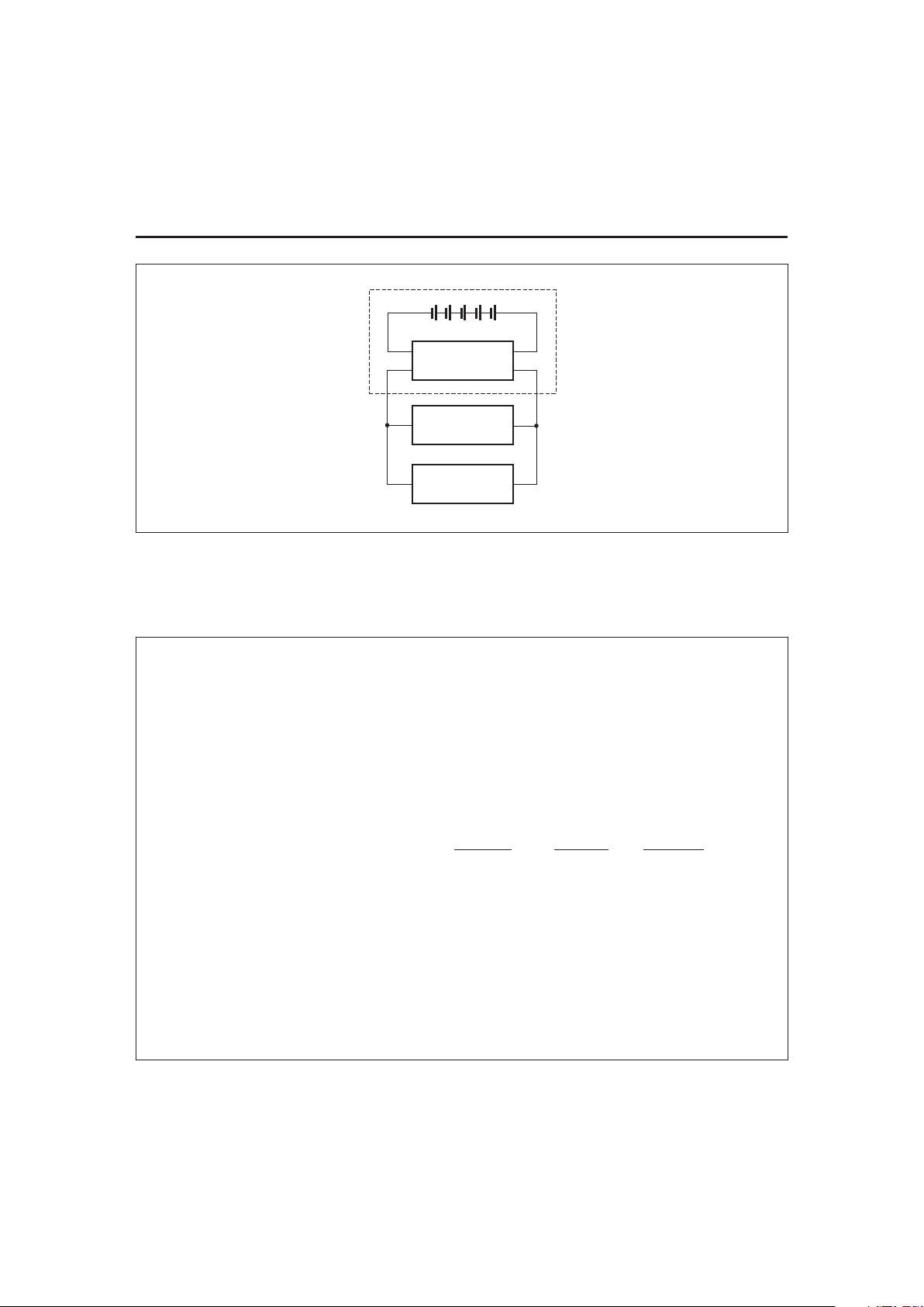
shown in the bq2004 data sheet. The bq2164 is optimized for
temperature termination with the thermistor provided with
the development kit. Figure 1 shows how the module con
-
nects to the cells.
The sense resistor value and type should also be specified
on the configuration sheet. The two options available are
a 3W through-hole type or a 1W surface-mount type.
Please refer to the application note entitled “A Tutorial for
Gas Gauging” to select the proper value.
A module development kit is also available for the
bq2164. The bq2164B-KT includes one configured module and the following:
1) A serial interface board that allows connection to
the RS-232 port of an AT-compatible computer.
2) Menu-driven software with the bq2164 to display
charge/discharge activity and to allow user inter
-
face to the bq2014 from any standard DOS PC.
3) Source code for the TSR.
4) A Philips 10K NTC Thermistor type 2322-640-
63103.
Pin Description
P1
DQ/Serial communication port
P2
BAT+/Battery positive
P3
PACK+/Pack positive
P4
PACK-/Pack negative
P5
BAT-/Battery negative
P6
THERM+/Thermistor positive
P7
THERM-/Thermistor negative
P8
MOD/Fast charge control output
1
NiCd or NiMH Gas Gauge Module
with Fast-Charge Control
bq2164
9/96
Page 2
5-2
bq2164
FG216401.eps
Battery Pack
P5
P4
bq2164
Load
Charger
Cells
PACK+PACK-
P2
P3
Figure 1. Module Connection Diagram
Customer Name: ___________________________________________________________________________
Contact: _________________________________________ Phone: ______________________________
Address: _________________________________________________________________________________
_________________________________________________________________________________
Sales Contact: ____________________________________ Phone: ______________________________
Number of series battery cells (5-10) ________________________________________
Battery type (NiCd or NiMH) ________________________________________
Battery pack capacity (mAh) ________________________________________
Discharge rate into load (2.0A max.) Min.
Avg. Max.
Sense resistor type:
(Thru-hole (3W) or surface-mount (1W)) ________________________________________
Sense resistor size in mΩ(0.1Ωstandard) ________________________________________
Fast charge current (2.0A max.) ________________________________________
Charge voltage (V) ________________________________________
Temperature termination (enabled/disabled) ________________________________________
PVD or -∆V termination ________________________________________
FAE Approval _____________________________________ Date ________________________________
Table 1. bq2164 Module Configuration
Page 3
5-3
bq2164
200K
R21
BAT+
VIN
GND
VOUT
SCI7710YBA
U2
1
2
3
BAT+
P4
VCC
P2
P3
10K
R14
10K
R13
SI9430DY
Q3
5678
FMMT3904
Q2
300K
R18
TP9
VCC
100K
R20
100K
R19
BAV70
D2
P8
1
BAV99
D1
100K
R2
100
R4
P1
VCC
0.1UF
C2
0.1UF
C3
R3
VCC
10K
R17
P5
SENSE_RESISTOR
R15A
100K
R1
0.1UF
C1
SNS
LED1
LED2
VSS
VCC
MOD
DIS
INH
BAT
TS
TCO
TM2
TM1
VSEL
DSEL
DCMD
BQ2004
U1
1
2
3
4
5
6
7
89
10
11
12
13
14
15
16
1K
R32
VCC
1K
R35
1K
R36
1K
R37
1K
R341KR33
RB_TCO
R6
RA_TCO
R5
0.1UF
C7
0.1UF
C4
TP3
100K
R10
100K
R11
100K
R16
0.1UF
C5
VCC
0.1UF
C6
100K
R9
RB_TS
R8
RA_TS
R7
P7
CHG
DISP
DONE
SR
SB
EMPTY
DQ
REF
VSS
SEG5
SEG4
SEG3
SEG2
SEG1
VCCLCOM
BQ2014
U3
1
2
3
4
5
6
710
11
12
13
14
15
16
P6
100K
R26
100K
R31
100K
R25
100K
R30
100K
R24
100K
R29
100K
R23
100K
R28
100K
R27
100K
R22
VCC
VCC
R15B
R15C
R15D
FMMT3904
Q1
TP4
TP1
TP2
TP10
TP5
TP6
TP7
TP8
TP11
TP12
FMMT3904
Q4
TP13
BAV70
D3
BAT+
PACK+
DQ
BAT-
MOD
THERM+
PACK-
THERM-
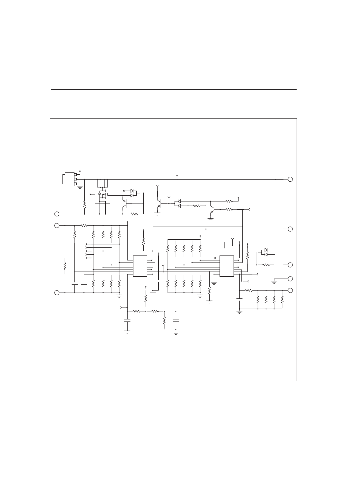
bq2164 Schematic
Note: Schematic shows components that may not be placed on the
board, depending on the configuration.
Page 4

5-4
bq2164
bq2164 Board
Page 5

5-5
bq2164
Absolute Maximum Ratings
Symbol Parameter Minimum Maximum Unit Notes
P
SR
Continuous sense resis
-
tor power dissipation
- 3 W Thru-hole sense resistor
- 1 W Surface-mount sense resistor
V
CHG
Charging voltage - 20 V
T
OPR
Operating temperature 0 +70 °C Commercial
T
STR
Storage temperature -40 +85 °C
Note: Permanent device damage may occur if Absolute Maximum Ratings are exceeded. Functional opera
-
tion should be limited to the Recommended DC Operating Conditions detailed in this data sheet. Expo
-
sure to conditions beyond the operational limits for extended periods of time may affect device reliability.
DC Electrical Characteristics (T
A=TOPR
)
Symbol Parameter Minimum Typical Maximum Unit Conditions/Notes
NumCell
Number of cells in battery
pack
5 - 10 -
BAT+ Positive terminal of pack GND
NumCell 1.2V* NumCell 1.8V*
V
BAT- Negative terminal of pack GND - 0.3 - GND+2.0 V
I
CC
Supply current at BAT+ ter
-
minal (no external loads)
- 200 300
µ
A
I
CHG
Charge current - - 2 A
I
DSCHG
Discharge current - - 2 A
R
DQ
Internal pull-down 500k - -
Ω
1
I
OL
Open-drain sink current DQ - - 5.0 mA
1
V
OL
Open-drain output low, DQ - - 0.5 V1IOL< 5mA
V
IHDQ
DQ input high 2.5 - - V
1
V
IHDQ
DQ input low - - 0.8 V
1
V
OS
Voltage offset 150
µ
V
1
Note: 1. Characterized on PCB, IC 100% tested.
Page 6

5-6
bq2164
DC Voltage and Temperature Thresholds (T
A=TOPR
)
Symbol Parameter Minimum Typical Maximum Unit Notes
V
EDVF
Final empty warning 0.93 0.95 0.97 V BAT+/NumCell
1
V
EDV1
First empty warning 1.03 1.05 1.07 V BAT+/NumCell
1
V
MCV
Maximum single-cell voltage 2.20 2.25 2.30 V BAT+/NumCell
1
V
SRO
SR sense range -300 - +2000 mV VSR+ V
OS
2
V
SRQ
Valid charge 375 - -
µ
VVSR+V
OS
2, 3
V
SRD
Valid discharge - - -300
µ
VVSR+V
OS
2, 3
V
SR1
Discharge compensation threshold -120 -150 -180 mV VSR+ V
OS
2
T
LTF
Low-temperature charging fault - 10 - °C
Low-temperature charge
inhibit/terminate
4
T
HTF
High-temperature charging fault - 45 - °C
High-temperature
charge inhibit
V
EDVC
Minimum charging cell voltage - 1 - V
Minimum cell voltage
to initiate charge
V
MCVC
Maximum charging cell voltage - 2 - V
Maximum cell voltage to
initiate or continue charge
R
∆T/∆
t
∆T/∆
t charge termination rate - 1 - °C/ min. @ 30°C
T
TCO
Maximum charging temperature - 50 - °C
High-temperature charge
termination
Notes: 1. At SB input of bq2014.
2. At SR input of bq2014.
3. Default value; value set in DMF register.
4. PVD termination disables the low-temperature fault charge termination.
Notes: 1. Requires configuration sheet (Table 1)
2. Example production part number: bq2164B-001
Ordering Information
bq2164 B —
Customer Code:
Blank = Sample or Pre-production
1
KT = Evaluation system
XXX = Customer-specific; assigned by Unitrode
2
Package Option:
B = Board-level product
Device:
NiCd or NiMH Gas Gauge Module with Fast-Charge Control
Page 7

IMPORTANT NOTICE
T exas Instruments and its subsidiaries (TI) reserve the right to make changes to their products or to discontinue
any product or service without notice, and advise customers to obtain the latest version of relevant information
to verify, before placing orders, that information being relied on is current and complete. All products are sold
subject to the terms and conditions of sale supplied at the time of order acknowledgement, including those
pertaining to warranty, patent infringement, and limitation of liability.
TI warrants performance of its semiconductor products to the specifications applicable at the time of sale in
accordance with TI’s standard warranty. Testing and other quality control techniques are utilized to the extent
TI deems necessary to support this warranty. Specific testing of all parameters of each device is not necessarily
performed, except those mandated by government requirements.
CERT AIN APPLICATIONS USING SEMICONDUCTOR PRODUCTS MAY INVOLVE POTENTIAL RISKS OF
DEATH, PERSONAL INJURY, OR SEVERE PROPERTY OR ENVIRONMENTAL DAMAGE (“CRITICAL
APPLICATIONS”). TI SEMICONDUCTOR PRODUCTS ARE NOT DESIGNED, AUTHORIZED, OR
WARRANTED TO BE SUITABLE FOR USE IN LIFE-SUPPORT DEVICES OR SYSTEMS OR OTHER
CRITICAL APPLICATIONS. INCLUSION OF TI PRODUCTS IN SUCH APPLICA TIONS IS UNDERSTOOD T O
BE FULLY AT THE CUSTOMER’S RISK.
In order to minimize risks associated with the customer’s applications, adequate design and operating
safeguards must be provided by the customer to minimize inherent or procedural hazards.
TI assumes no liability for applications assistance or customer product design. TI does not warrant or represent
that any license, either express or implied, is granted under any patent right, copyright, mask work right, or other
intellectual property right of TI covering or relating to any combination, machine, or process in which such
semiconductor products or services might be or are used. TI’s publication of information regarding any third
party’s products or services does not constitute TI’s approval, warranty or endorsement thereof.
Copyright 1999, Texas Instruments Incorporated
 Loading...