

Page 1
Features
ä
Complete and compact lithium-ion pack supervisor
ä
Provides overvoltage, undervoltage, and
overcurrent protection for two series Li-Ion cells
ä
Combines bq2058T with charge/discharge control
FETs
ä
Low side low on-resistance FETs
ä
Designed for battery pack integration
–
Direct connection for series battery terminals
–
Measures 1.70 X 0.70 inches
ä
Low standby and operating currents
General Description
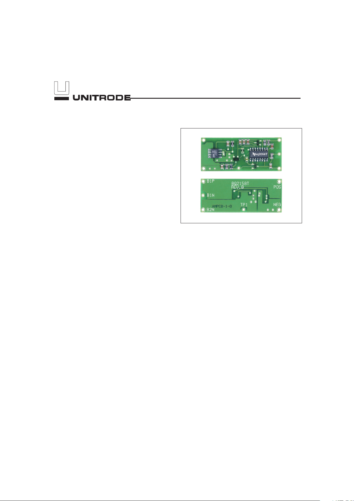
The bq2158T provides a complete solution for the supervision of two series Li-Ion cells. Designed for battery
pack integration, the bq2158T incorporates a bq2058T
Pack Supervisor, two FETs, and all other components required to monitor overvoltage, undervoltage, and overcurrent conditions. The board provides direct
connections for the negative and positive terminals of
each cell. See Figure 1. Please refer to the bq2058T
data sheet for specific information on the operation of
the bq2058T.
Unitrode configures the bq2158T based on the informa
-
tion in Table 1.
Pin Descriptions
B1P
Battery 1 positive input
B1N
Battery 1 negative input
B2N
Battery 2 negative input
POS
Pack positive
NEG
Pack negative
1
Two Series Cell
Li-Ion Pack Supervisor Module
Preliminary bq2158T
4/99
Page 2

2
Customer Name: ___________________________________________________________________________
Contact: _________________________________________ Phone: ______________________________
Address: _________________________________________________________________________________
_________________________________________________________________________________
Sales Contact: ____________________________________ Phone: ______________________________
Overvoltage threshold (4.25V) ________________________________________
Charge current (3.8A max.) ________________________________________
Discharge current (3.8A max.) ________________________________________
FAE approval: ____________________________________ Date:________________________________
Table 1. bq2158T Module Configuration
bq2158T
Preliminary
Page 3
Operation
The bq2158T monitors each series element for undervoltage, over-voltage, and over-current conditions. If a
cell falls below V
UV
for t
UVD
, the bq2158T enters into
sleep mode. The bq2158T wakes up and enables dis
-
charge if a voltage, V
CD
higher than the battery voltage,
is applied across POS and NEG. Charging is disabled if
a cell exceeds V
OV
for t
OVD
, and can resume when the
cell falls below the V
CE
threshold. The bq2158T turns
the discharge FET off if the steady state load current ex
-
ceeds I
OC
for t
OCD
and turns it back on if the load is re
-
moved.
3
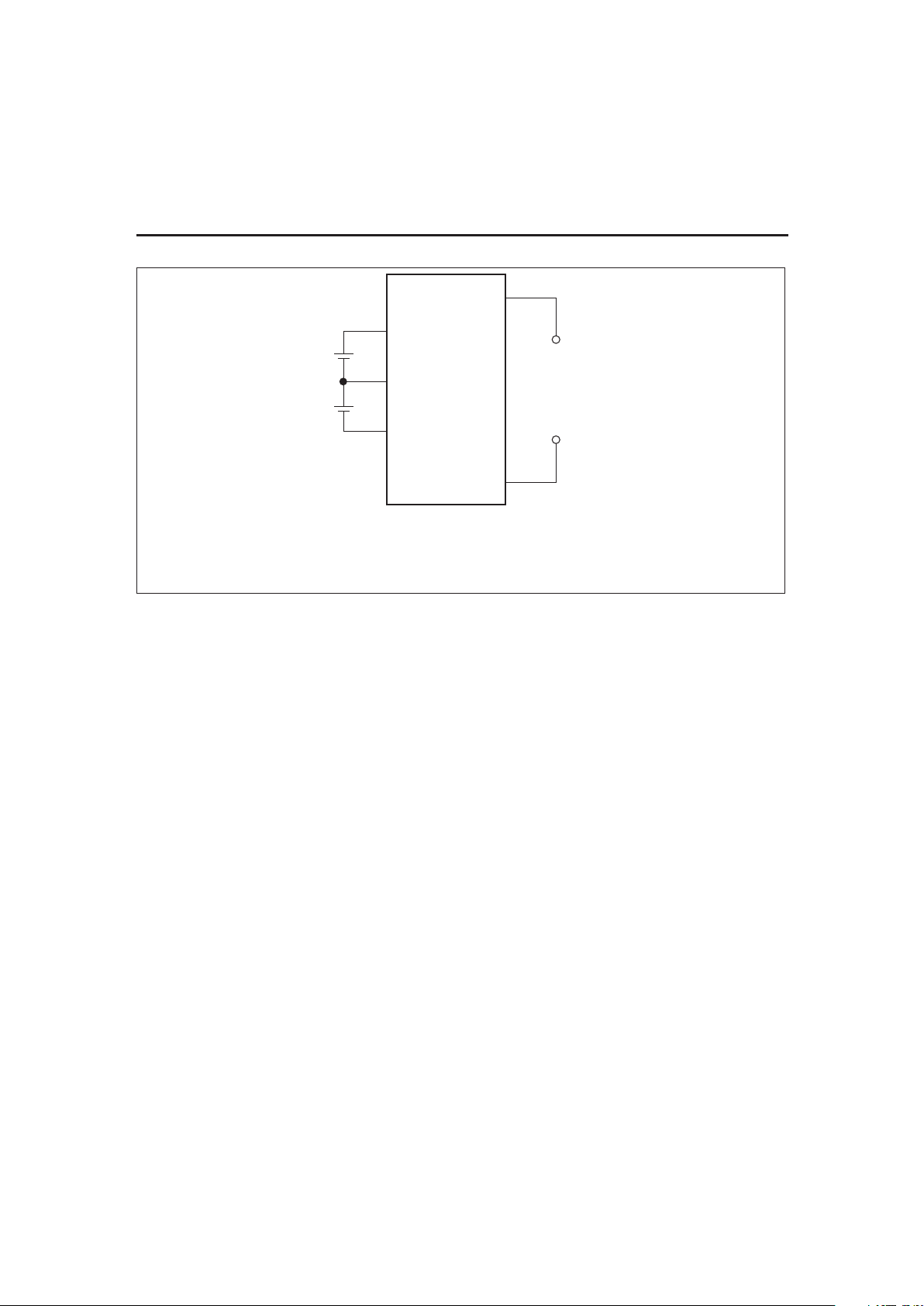
FG2158Tcd.eps
Load
or
Charger
POS
NEG
B1P
B1N
B2N
Note: B1P, B2N, POS, and NEG accomodate a #20 AWG stranded wire.
B1N accomodates a #24 AWG stranded wire.
Figure 1. Module Connection Diagram
Preliminary
bq2158T
Page 4

4
bq2158t-b6/18/98
bq2158T Schematic
bq2158T
Preliminary
Page 5

5
.700
.000
2x .055
3x 1.645
2x .055
2x .645
.000
.355
POS
Q3
B1P
B1N
B2N
.068
1.700
U1
TP1
Q1
C7
C3
C8
C2C5C6
C4
C1
D1
R1
Q2
R6
R7
R5
R3
R2
R4
NEG
.031
LAYER 1
LAYER 2
bq2158T Board
Preliminary
bq2158T
Page 6

6
Absolute Maximum Ratings
Symbol Parameter Value Unit Conditions
V
OP
Supply voltage (B1P to B2N) 12 V DC
V
TR
Maximum transient voltage (B1P to B2N) 32 V
Maximum duration =
1.5µs
V
CHG
Charging voltage (POS to NEG) 12 V
I
CHG
Continuous charge/discharge current 3.8 A
V
OP
> 4V
T
A
= 25°C
T
OPR
Operating temperature -30 to +70 °C
T
STG
Storage temperature -55 to +125 °C
Note: Permanent device damage may occur if Absolute Maximum Ratings are exceeded. Functional operation
should be limited to the Recommended DC Operating Conditions detailed in this data sheet. Exposure to con
-
ditions beyond the operational limits for extended periods of time may affect device reliability.
DC Electrical Characteristics (T
A
= T
OPR
)
Symbol Parameter Minimum Typical Maximum Unit Conditions/Notes
V
OP
Operating voltage, B1P to
B2N
4.0 - 12 V
I
CCA
Operating current - 26 43
µ
A
I
CCS
Sleep current - 0.7 1.5
µ
A
No load across POS and
NEG
R
ON
On resistance, B2N to NEG - - 100
m
Ω
T
A
= 25°C
V
OP
= 4.5V
bq2158T
Preliminary
Page 7

7
DC Thresholds (T
A
= T
OPR
)
Symbol Parameter Value Tolerance Unit Notes
V
OV
Overvoltage threshold 4.25
±
50mV V
V
CE
Charge enable voltage VOV- 100mV
±
50mV V
V
UV
Undervoltage limit 2.25
±
100mV V
I
OC
Overcurrent limit
3.3 A
T
A
= 25°C
3A
T
A
= 60°C
t
UVD
Undervoltage delay 950
±50%
ms
T
A
= 30°C
V
CD
Charge detect threshold 70 -60, +80 mV
t
OVD
Overvoltage delay 950
±50%
ms
T
A
= 30°C
t
OCD
Overcurrent delay 12
±60%
ms
T
A
= 30°C
Ordering Information
Notes: 1. Requires configuration sheet (Table 1)
2. Example production part number: bq2158TB-001
bq2158T B —
Customer Code:
Blank = Sample or Pre-production
1
XXX = Customer-specific; assigned by Unitrode
2
Package Option:
B = Board-level product
Device:
Two-Series Cell Li-Ion Supervisor Module
Preliminary
bq2158T
Page 8

IMPORTANT NOTICE
T exas Instruments and its subsidiaries (TI) reserve the right to make changes to their products or to discontinue
any product or service without notice, and advise customers to obtain the latest version of relevant information
to verify, before placing orders, that information being relied on is current and complete. All products are sold
subject to the terms and conditions of sale supplied at the time of order acknowledgement, including those
pertaining to warranty, patent infringement, and limitation of liability.
TI warrants performance of its semiconductor products to the specifications applicable at the time of sale in
accordance with TI’s standard warranty. Testing and other quality control techniques are utilized to the extent
TI deems necessary to support this warranty. Specific testing of all parameters of each device is not necessarily
performed, except those mandated by government requirements.
CERT AIN APPLICATIONS USING SEMICONDUCTOR PRODUCTS MAY INVOLVE POTENTIAL RISKS OF
DEATH, PERSONAL INJURY, OR SEVERE PROPERTY OR ENVIRONMENTAL DAMAGE (“CRITICAL
APPLICATIONS”). TI SEMICONDUCTOR PRODUCTS ARE NOT DESIGNED, AUTHORIZED, OR
WARRANTED TO BE SUITABLE FOR USE IN LIFE-SUPPORT DEVICES OR SYSTEMS OR OTHER
CRITICAL APPLICATIONS. INCLUSION OF TI PRODUCTS IN SUCH APPLICA TIONS IS UNDERSTOOD T O
BE FULLY AT THE CUSTOMER’S RISK.
In order to minimize risks associated with the customer’s applications, adequate design and operating
safeguards must be provided by the customer to minimize inherent or procedural hazards.
TI assumes no liability for applications assistance or customer product design. TI does not warrant or represent
that any license, either express or implied, is granted under any patent right, copyright, mask work right, or other
intellectual property right of TI covering or relating to any combination, machine, or process in which such
semiconductor products or services might be or are used. TI’s publication of information regarding any third
party’s products or services does not constitute TI’s approval, warranty or endorsement thereof.
Copyright 1999, Texas Instruments Incorporated
 Loading...