

Datasheet BQ2145MODULE, BQ2145LMODULE, BQ2145LB-KT, BQ2145B-KT Datasheet (Texas Instruments)
Page 1
Features
ä
Complete smart battery solution for NiCd, NiMH,
and Li-Ion battery packs
ä
Based on the bq2945 Gas Gauge IC
ä
Accurate measurement of available battery
capacity
ä
Designed for battery pack integration:
–
Measures only 2.5 (L) x 0.7 (W) inches
–
Includes Gas Gauge IC, configuration
EEPROM, and sense resistor
–
Five onboard state-of-charge LEDs with
push-button activation
–
Low operating current for minimal battery
drain
ä Critical battery information available over two-wire
serial port
General Description
The bq2145 Smart Battery Module provides a complete
solution for the design of intelligent battery packs. The
bq2145 uses the SMBus protocol and supports Smart
Battery Data commands in the SMB/SBD specifications.
Designed for battery pack integration, the bq2145 com
bines the bq2945 Gas Gauge IC with a serial EEPROM
on a small printed circuit board. The board includes all
the necessary components to accurately monitor battery
capacity and communicate critical battery parameters to
the host system or battery charger. The bq2145 also in
cludes five LEDs. The push-button switch activates the
LEDs to show remaining battery capacity in 20% incre
ments.
Contacts are provided on the bq2145 for direct connec
tion to the battery stack (B+, B-) and the two-wire inter
face (C, D). Please refer to the bq2945 data sheet for
specific information on the operation of the Gas Gauge
and communication interface.
Unitrode configures the bq2145 based on the informa
tion requested in Table 1. The configuration defines the
pack voltage, capacity, and chemistry and charge control
parameters. The Smart Battery Module uses the on
board sense resistor to track charge and discharge activ
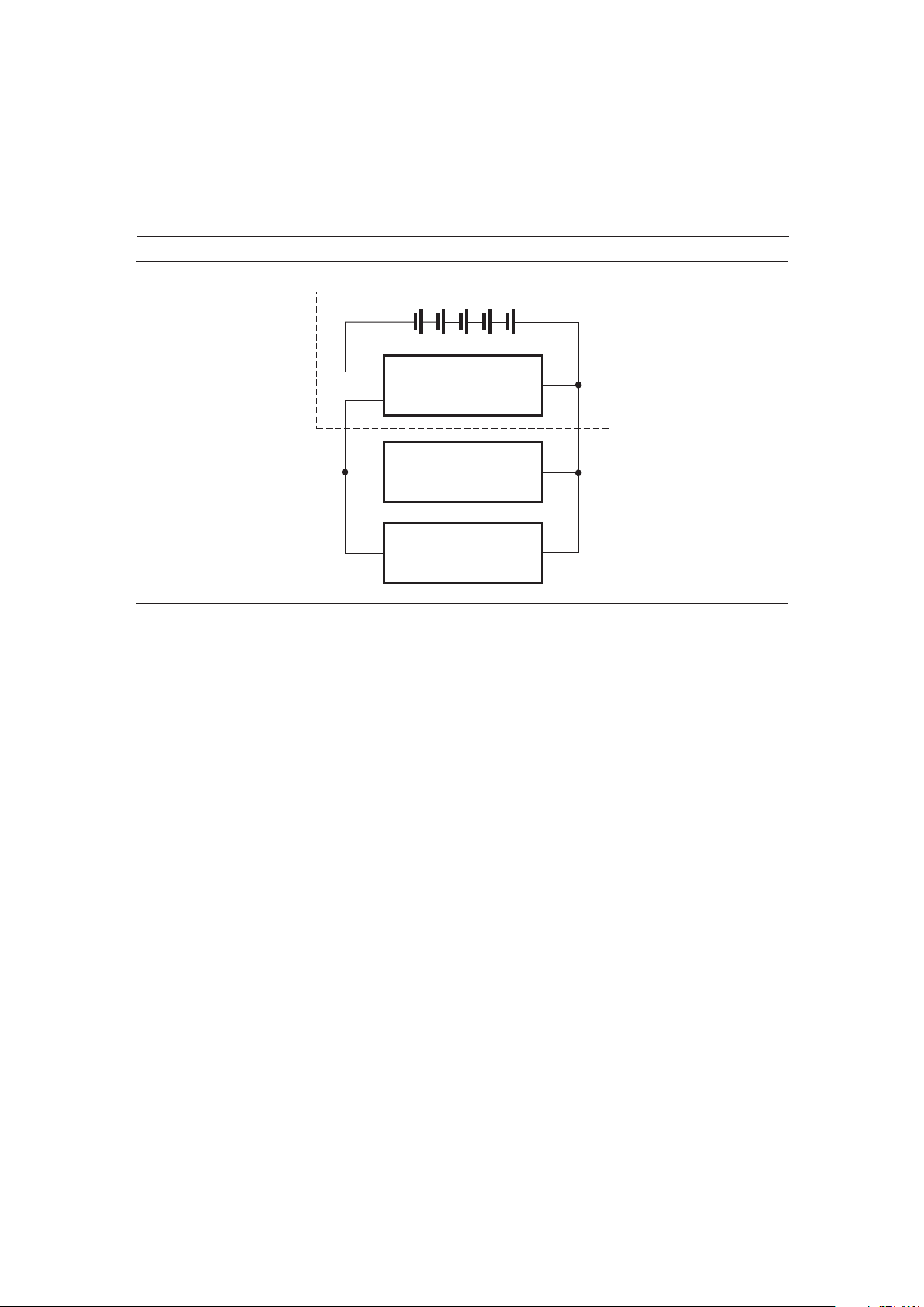
ity of the battery pack. Figure 1 shows how the module
connects to the cells.
A module development kit is also available for the
bq2145. The bq2145B-KT or the bq2145LB-KT includes
one configured module and the following:
1) An EV2200-45 interface board that allows connection to the serial port of any AT-compatible computer.
2) Menu-driven software to display charge/discharge
activity and to allow user interface to the Gas
Gauge IC and serial E
2
PROM from any standard
Windows 95 or 3.1x PC.
Pin Descriptions
B+
BAT+/Battery positive/Pack positive
P-
PACK-/Pack negative
C
SMBC/Communications clock
D
SMBD/Serial data
B-
BAT-/Battery negative
CP2
Control pin 2
CP1
Control pin 1
1
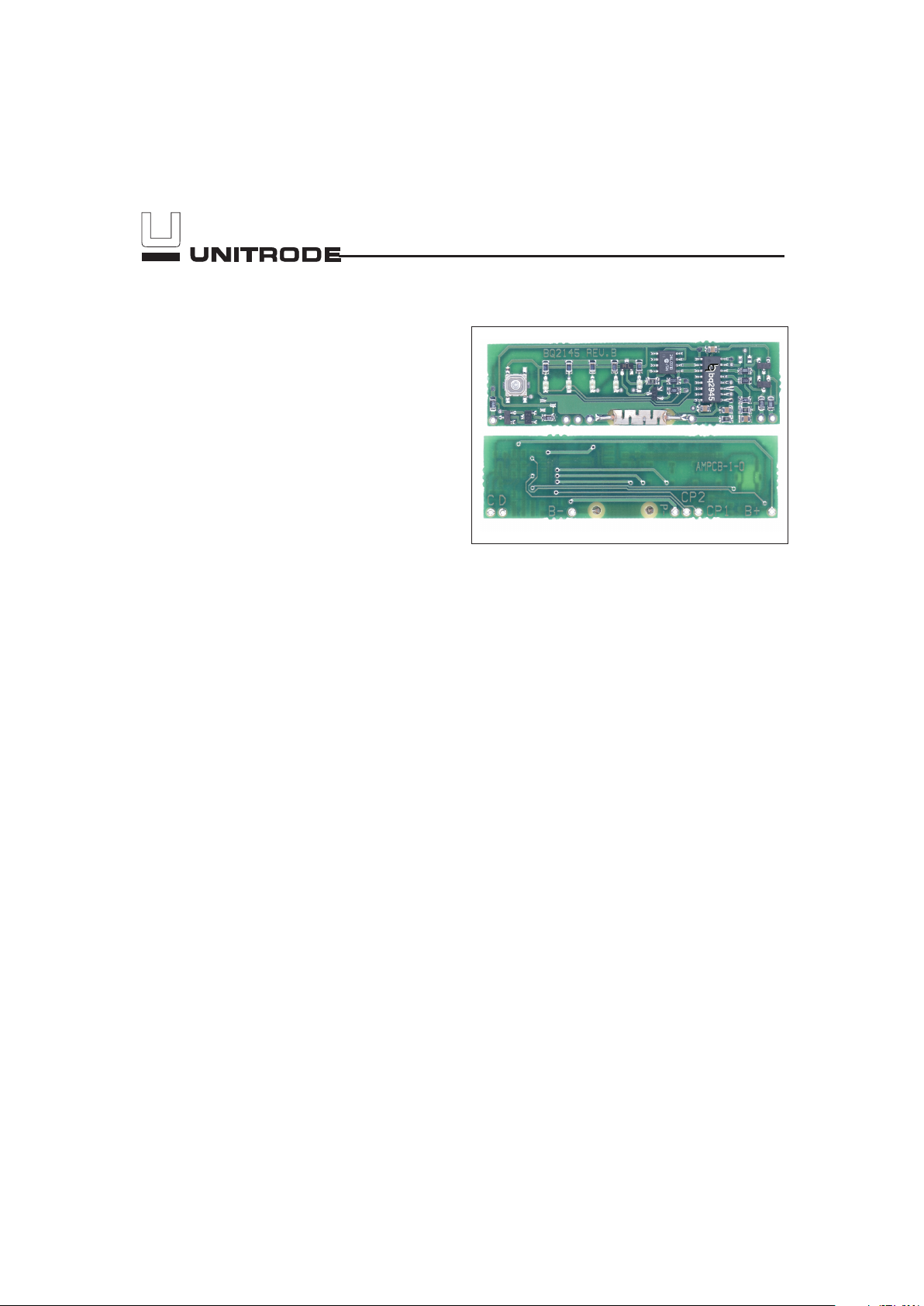
Smart Battery Module with LEDs
Preliminary
bq2145
5/99
Page 2
2
FG2145-1.eps
Battery Pack
B-
P-
B+bq2145
Load
Charger
Cells
PACK+PACK-
Figure 1. Module Connection Diagram
bq2145
Preliminary
Page 3

3
Customer Name: ______________________________________________________________________________________________
Contact: _______________________________________________________ Phone:____________________________
Address:________________________________________________________________________________________________
Sales Contact: __________________________________________________ Phone: ____________________________
Board Configuration
LEDs and switch ________________ Yes or No
Display mode ________________ Relative or Absolute
Discharge rate (3.0A max.) Min ____________ Avg ____________ Max ___________
Duration at max. discharge ________________
Number of series cells ________________
EEPROM Configuration Typical Values
NiMH Li-Ion
Remaining time alarm (min) _______________ Sets the low time alarm level 10 min 10 min
Remaining capacity alarm
(mAh)
_______________ Sets the low capacity alarm level C/10 C/10
Charging voltage (mV) _______________ Sets the requested charging voltage 65535 4.1V/cell
Design cpaacity (mAh) _______________ Defines the battery pack capacity 3000 3600
Design voltage (mV) _______________ Defines the battery pack voltage 12000 10800
Manufacturer date _______________ Battery pack manufacturer date mm/dd/yy mm/dd/yy
Serial number _______________ Battery pack serial number 0-65535 0-65535
Fast-charging current (mA) _______________ Sets the requested charging current 1C 1C
Maintenance charging
current (mA) _______________
Sets the requested maintenance charging
current C/20 0
Li-Ion taper current (mA) _______________ Sets the upper limit for charge termination NA C/10
Maximum overcharge (mAh) _______________ Sets the maximum amount of overcharge 256mAh 128mAh
Maximum temperature (°C)
_______________ Sets the maximum charge temperature
61°C61°C
∆T/∆t (°C/min)
_______________ Sets the termination rate 3°C/3min 4.6°C/20s
Fast-charge efficiency (%) _______________ Sets the fast-charge efficiency factor 95% 100%
Maintenance charge effi
-
ciency (%)
_______________ Sets the maintence charge efficiency factor 80% 100%
Self-discharge rate (%/day) _______________ Sets the batterys self-discharge rate 1.5%/day 0.2%/day
EDV1 (mV) _______________ Sets the initial end-of-discharge warning 1.05V/cell 3.0V/cell
EDVF (mV) _______________ Sets the final end-of-discharge warning 1.0V/cell 2.8V/cell
Hold-off timer for ∆T/∆t (sec.)
_______________
Sets the hold off period for ∆T/∆t
termination
180s 320s
Manufacturer name _______________ Programs manufacturer’s name (11 char.
max)
bq bq
Device name _______________ Programs device name (7 char. max) bq36 bq202
Chemistry _______________ Programs pack’s chemistry (7 char. max) NiMH LION
Manufacturer data _______________ Open field (5 char. max) 2040 2040
FAE Approval ____________________________________ Date: ____________
Table 1. bq2145 Module Configuration
Preliminary
bq2145
Page 4

4
D
1
100K
R17
1
2
BZX84C6V2
D9
1
2
3
OPTIONAL
C4
12
330
R16
12
P-
1
0.1UF
C5
12
B+
1
TP6
1
C
1
100
R6
12
TP1
1
TP2
1
100
R8
12
TP3
1
CP2
1
VCC
330
R15
12
SDA
SCL
WP
VCC
VSS
A2
A1
A0
24LC01
U2
1
2
3
45
6
7
8
330
R3
12
VCC
10K
R12
1
2
10K
R13
1
2
COLOR
D3
12
COLOR
D4
12
BAV99
D7
1
2
3
VCC
R11
12
1%
B-
1
R5
1
2
1%
R4
1
2
1%
0.1UF
C1
1
2
0.1UF
C3
1
2
100
R18
12
100K
R10
12
COLOR
D5
12
330
R2
12
COLOR
D2
12
DISPLAY
SW1
12
3 4
100
R9
12
100
R7
12
BAV99
D6
1
2
3
2N7002
Q1
1
2
3
TP4
1
BAV99
D8
1
2
3
COLOR
D1
12
VCC
0.1UF
C2
12
TP5
1
330
R14
12
3W
0.05
R1
1
2
BSS84ZX
Q2
1
2
3
CP1
1
CP2
CPI DISP
SMBD
SMBC
VOUTVCC
SR
SB
REF
VSS
SEG5
SEG4
SEG3
SEG2
SEG1
bq2945
U1
1
2
3
4
5
6
7
8
10
9
11
12
13
14
15
16
TP7
1
BAW56
D10
1
2
3
SMBC
SMBD
BAT+
BAT-
1
SEE CHART 1 FOR RESISTOR VALUES.1
11
1
86.5K1M
909K
604K
402K
162K
909K
909K
86.5K
909K
NiMH
100K
100K
100K
100K
100K
100K
100K
909K
806K
698K
499K
698K
499K
301K
R4
LiION
12
10
9
8
6
4
3
2
CHART 1
# OF CELLS R11R5
PACK-
OPTIONAL 6.2V
bq2145 Schematic
bq2145
Preliminary
Page 5

5
bq2145 Board
Preliminary
bq2145
Page 6

6
bq2145
Preliminary
bq2145 B – XXX
Package Option:
B = Board-level product
Device:
Smart Battery Module with LEDs
Customer Code:
Blank = Sample or Pre-production
1
KT = Evaluation system
XXX = Customer-specific; assigned by Unitrode
2
Ordering Information
Notes: 1. Requires configuration sheet (see Table 1)
2. Example production part number: bq2145LB-001
LED Option:
L = LEDs plus switch
Blank = No LEDs or switch
Page 7

IMPORTANT NOTICE
T exas Instruments and its subsidiaries (TI) reserve the right to make changes to their products or to discontinue
any product or service without notice, and advise customers to obtain the latest version of relevant information
to verify, before placing orders, that information being relied on is current and complete. All products are sold
subject to the terms and conditions of sale supplied at the time of order acknowledgement, including those
pertaining to warranty, patent infringement, and limitation of liability.
TI warrants performance of its semiconductor products to the specifications applicable at the time of sale in
accordance with TI’s standard warranty. Testing and other quality control techniques are utilized to the extent
TI deems necessary to support this warranty. Specific testing of all parameters of each device is not necessarily
performed, except those mandated by government requirements.
CERT AIN APPLICATIONS USING SEMICONDUCTOR PRODUCTS MAY INVOLVE POTENTIAL RISKS OF
DEATH, PERSONAL INJURY, OR SEVERE PROPERTY OR ENVIRONMENTAL DAMAGE (“CRITICAL
APPLICATIONS”). TI SEMICONDUCTOR PRODUCTS ARE NOT DESIGNED, AUTHORIZED, OR
WARRANTED TO BE SUITABLE FOR USE IN LIFE-SUPPORT DEVICES OR SYSTEMS OR OTHER
CRITICAL APPLICATIONS. INCLUSION OF TI PRODUCTS IN SUCH APPLICA TIONS IS UNDERSTOOD T O
BE FULLY AT THE CUSTOMER’S RISK.
In order to minimize risks associated with the customer’s applications, adequate design and operating
safeguards must be provided by the customer to minimize inherent or procedural hazards.
TI assumes no liability for applications assistance or customer product design. TI does not warrant or represent
that any license, either express or implied, is granted under any patent right, copyright, mask work right, or other
intellectual property right of TI covering or relating to any combination, machine, or process in which such
semiconductor products or services might be or are used. TI’s publication of information regarding any third
party’s products or services does not constitute TI’s approval, warranty or endorsement thereof.
Copyright 1999, Texas Instruments Incorporated
 Loading...