

Page 1
Features
ä
Complete bq2011 Gas Gauge solution for NiCd
packs in high discharge rate applications
ä
Five surface-mounted LEDs to display
state-of-charge information
ä
Battery state-of-charge monitoring for 4- to 12-cell
series applications
ä
On-board regulator allows direct connection to the
battery
ä
Battery information available over a single-wire
bidirectional serial port
ä
Nominal capacity pre-configured
ä
Compact size for battery pack integration
General Description
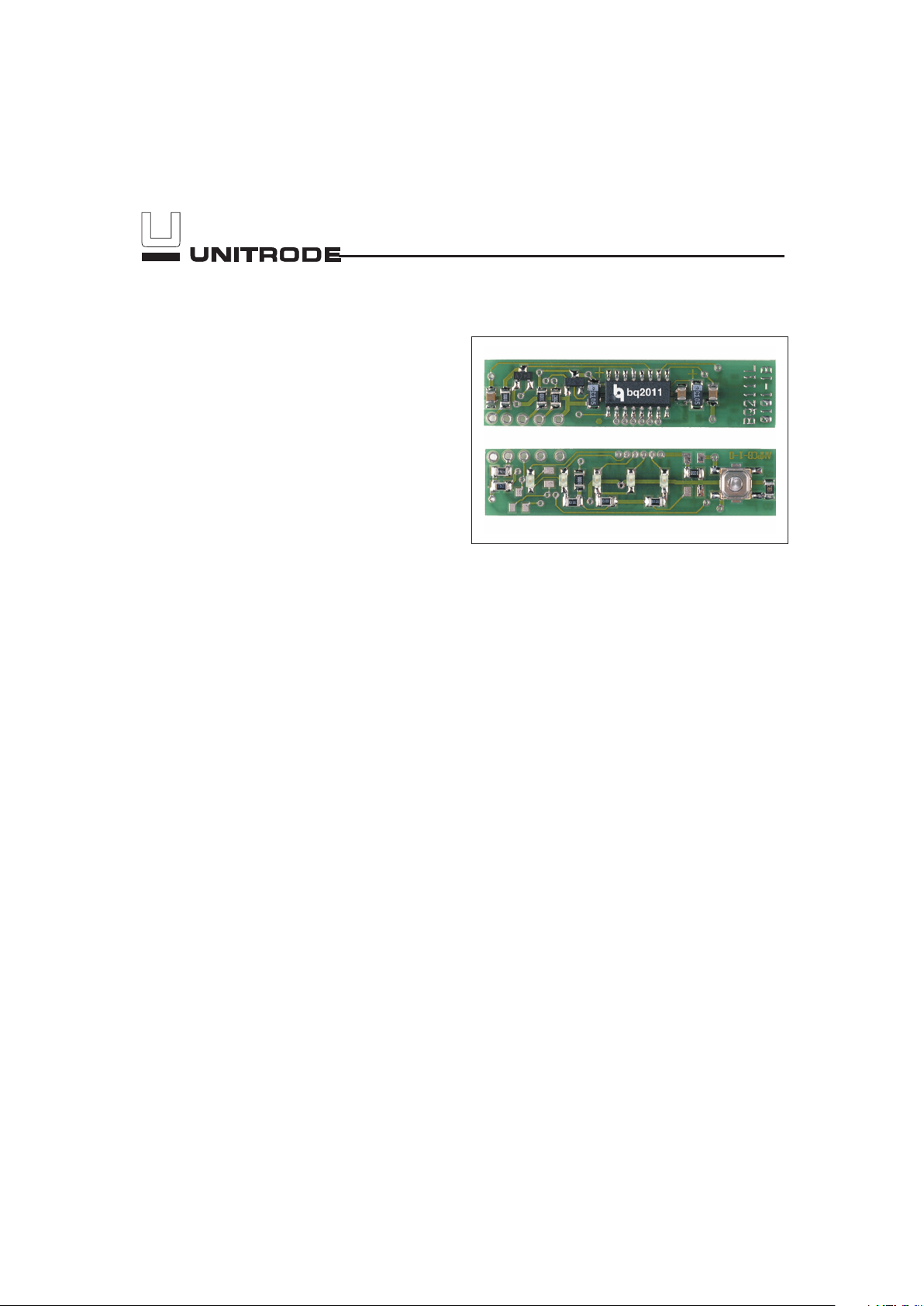
The bq2111L Gas Gauge Module provides a complete
and compact solution for capacity monitoring of NiCd
battery packs in high discharge rate applications such
as power tools. Designed for battery pack integration,
the bq2111L incorporates a bq2011 Gas Gauge IC, five
surface-mounted LEDs, and the other discrete components necessary to monitor and display accurately the
capacity of 4- to 12 -series cells. The only external compo-
nent required is a low-value sense resistor connected be
tween GND and PACK-. Contacts are also provided on
the bq2111L for direct connection to the battery stack
and the serial communications port (DQ). The battery
stack should be connected between BAT+ and GND.
Please refer to the bq2011 data sheet for the specifics on
the operation of the Gas Gauge.
Unitrode configures the bq2111L based on the informa
tion requested in Table 1. The configuration defines the
number of series cells and the nominal battery pack ca
pacity. The bq211L module uses the absolute LED dis
play to indicate battery capacity. In this mode, the
remaining capacity is represented as a percentage of the
programmed capacity.
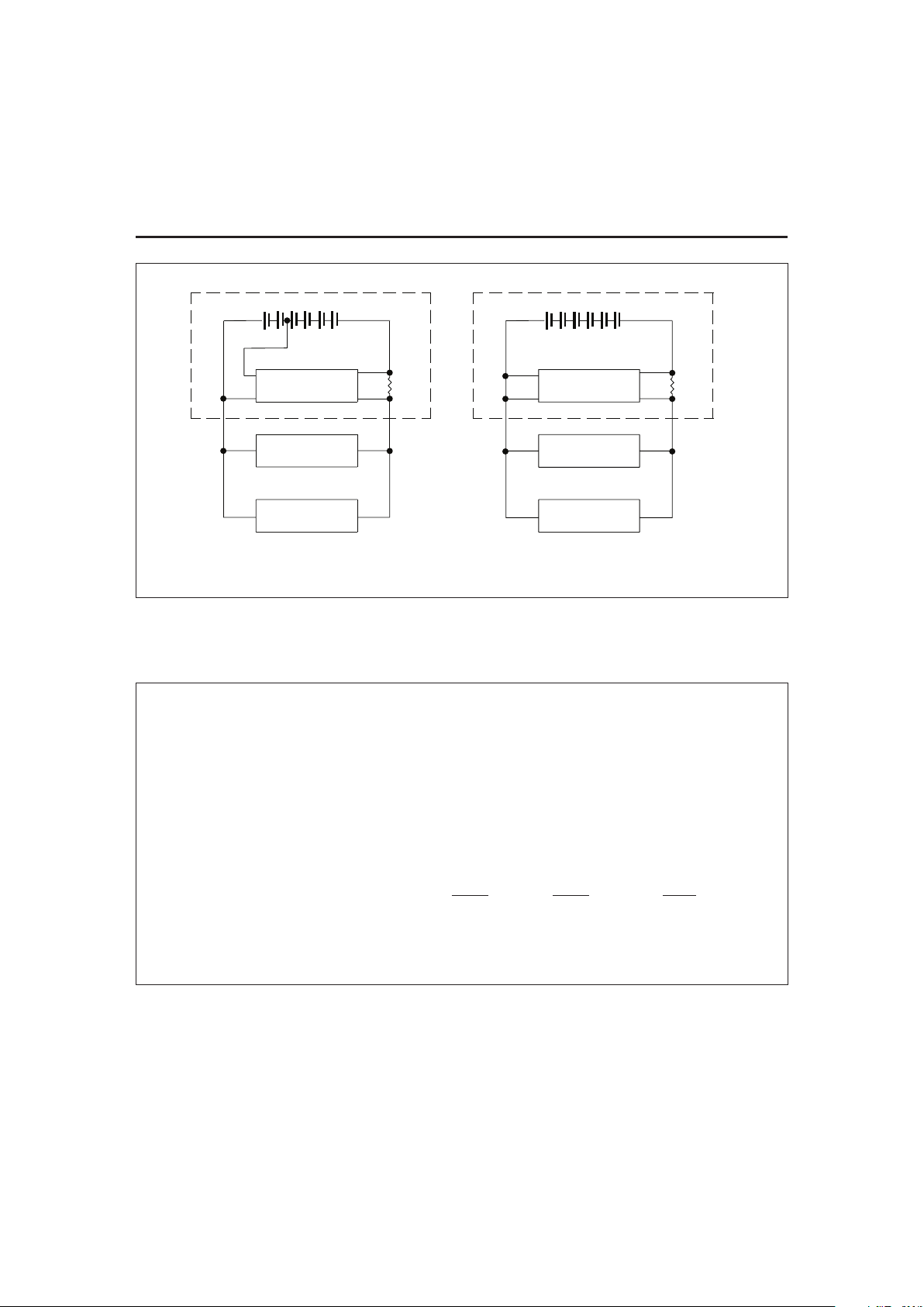
The bq2111L can operate directly from four series cells
within the pack using the LBAT+ supply input. For four
series cell applications or applications using the onboard regulator, LBAT+ should be connected to BAT+.
Please refer to Figure 1 for module connection illustra
tions.
A module development kit is also available for the
bq2111L. The bq2111LB-KT includes one configured
module and the following:
1) An interface board that allows connection to the serial port of an AT-compatible computer.
2) Menu-driven software with the bq2111L to display
charge/discharge activity and to allow user interface to the bq2011 from any standard DOS PC.
3) Source code for the TSR.
Pin Descriptions
P1
DQ/Serial communication port
P2
BAT+/Battery positive/Pack positive
P3
LBAT+/Four--cell power
P4
PACK-/Pack negative
P5
GND/Ground
1
NiCd Gas Gauge Module with LEDs
for High Discharge Rates
bq2111L
7/96
Page 2
2
bq2111L
Customer Name: ___________________________________________________________________________
Contact: _________________________________________ Phone: ______________________________
Address: _________________________________________________________________________________
_________________________________________________________________________________
Sales Contact: ____________________________________ Phone: ______________________________
Number of series battery cells (4–12) ________________________________________
Sense resistor size in m
Ω
1
________________________________________
Battery pack capacity (mAh) ________________________________________
Discharge rate(A) Min.
Avg. Max.
Charge rate (A) ________________________________________
FAE approval: _____________________________________ Date:________________________________
Table 1. bq2111L Module Configuration
Note: 1. Sense resistor is not included with board.
FG-130
Charger
Load
bq2111L
Cells
Battery Pack
P5
P4
Sense
Resistor
P3
P2
PACK+
PACK-
(b) Regulated Supply
(a) 4-Cell Supply
Charger
Load
PACK+
P2
P3
Battery Pack
P4
bq2111L
P5
Resistor
PACK-
Sense
Cells
Figure 1. Module Connection Diagram
Page 3
3
bq2111L
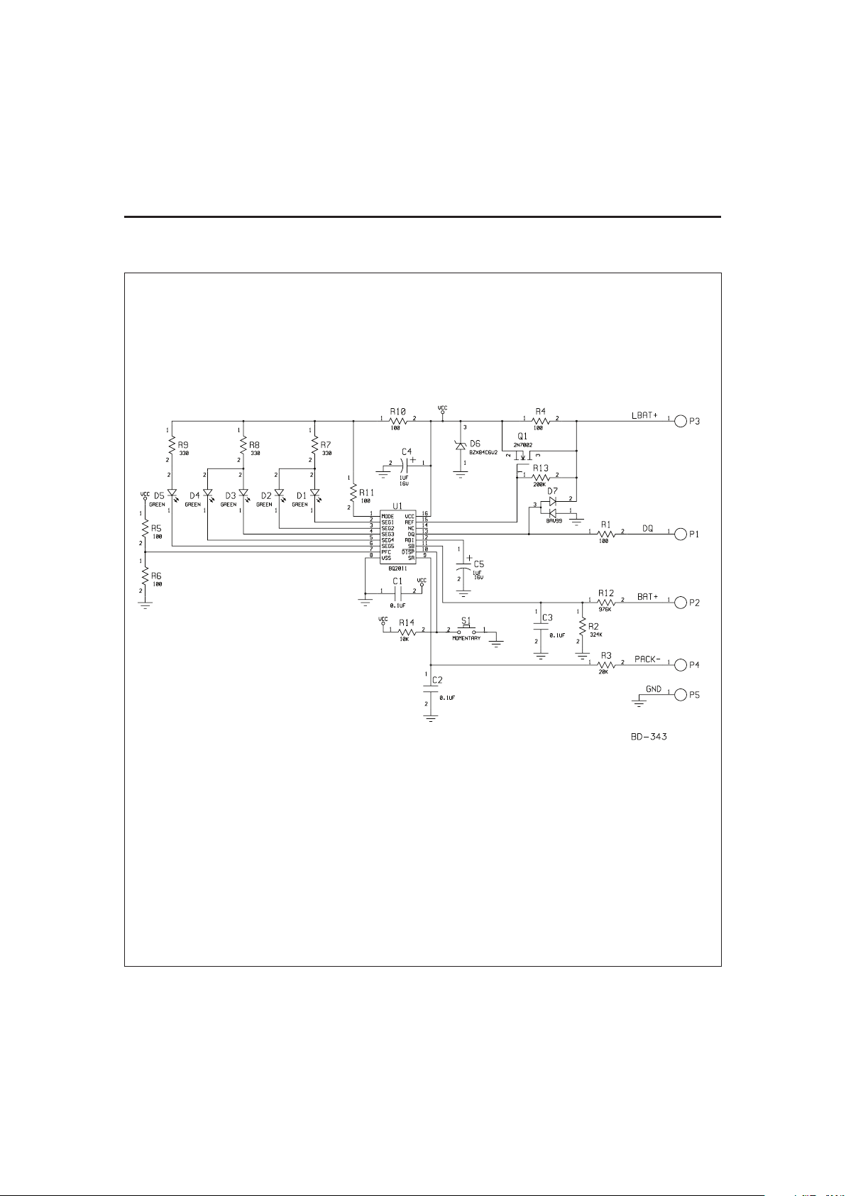
bq2111L Example Schematic
Note: Schematic shows components which may not be placed on the
board, depending upon the configuration.
Page 4

4
bq2111L Board
bq2111L
Page 5

5
Absolute Maximum Ratings
Symbol Parameter Minimum Maximum Unit Notes
V
CC
Relative to V
SS
-0.3 +7.0 V bq2011
All other pins Relative to V
SS
-0.3 +7.0 V bq2011
T
OPR
Operating temperature 0 +70 °C Commercial
T
STR
Storage temperature -40 +85 °C
Note: Permanent device damage may occur if Absolute Maximum Ratings are exceeded. Functional opera
-
tion should be limited to the Recommended DC Operating Conditions detailed in this data sheet. Expo
-
sure to conditions beyond the operational limits for extended periods of time may affect device reliability.
DC Electrical Characteristics (T
A=TOPR
)
Symbol Parameter Minimum Typical Maximum Unit Conditions/Notes
NumCell
Number of series cells in
battery pack
4 - 12 -
BAT+ Positive terminal of pack GND
NumCell 1.2V* NumCell 1.8V*
V
V
SR
Voltage across the sense resistor, P4 to P5
-0.3 - 2 V
V
CC
Supply voltage (direct cell
operation)
LBAT+
3.0 4.8 7.2 V
I
CC
Supply current at BAT+
terminal (no external
loads)
- 120 250
µ
A
R
DQ
Internal pull-down 500k - -
Ω
1
I
OL
Open-drain sink current
DQ
- - 5.0 mA
1
V
OL
Open-drain output low, DQ - - 0.5 V1IOL< 5mA
V
IHDQ
DQ input high 2.5 - - V
1
V
ILDQ
DQ input low - - 0.8 V
1
V
OS
Voltage offset 150
µ
V
1
bq2111L
Note: 1. Characterized on PCB, IC 100% tested.
Page 6

6
DC Voltage Thresholds (T
A
= T
OPR
)
Symbol Parameter Minimum Typical Maximum Unit Notes
V
EDV
Final empty warning 0.87 0.90 0.93 V BAT+/NumCell
1
V
MCV
Maximum single-cell voltage 1.95 2.0 2.05 V BAT+/NumCell
1
V
SR1
Discharge compensation threshold 20 50 75 mV VSR+ V
OS
2
V
SR2
Discharge compensation threshold 70 100 125 mV VSR+ V
OS
2
V
SR3
Discharge compensation threshold 120 150 175 mV VSR+ V
OS
2
V
SR4
Discharge compensation threshold 220 253 275 mV VSR+ V
OS
2
V
SRO
Sense resistor sense range -300 - +2000 mV VSR+ V
OS
2
V
SRQ
Valid charge - - -400
µ
VVSR+ V
OS
2
V
SRD
Valid discharge 500 - -
µ
VVSR+ V
OS
2
Notes: 1. At SB input of bq2011
2. At SR input of bq2011
bq2111L
Ordering Information
bq2111L B —
Customer Code:
Blank = Sample or Pre-production
1
KT = Evaluation system
XXX = Customer-specific; assigned by Unitrode
2
Package Option:
B = Board-level product
Device:
NiCd Gas Gauge Module with LEDs
Notes: 1. Requires configuration sheet (see Table 1)
2. Example production part number: bq2111LB-001
Page 7

IMPORTANT NOTICE
T exas Instruments and its subsidiaries (TI) reserve the right to make changes to their products or to discontinue
any product or service without notice, and advise customers to obtain the latest version of relevant information
to verify, before placing orders, that information being relied on is current and complete. All products are sold
subject to the terms and conditions of sale supplied at the time of order acknowledgement, including those
pertaining to warranty, patent infringement, and limitation of liability.
TI warrants performance of its semiconductor products to the specifications applicable at the time of sale in
accordance with TI’s standard warranty. Testing and other quality control techniques are utilized to the extent
TI deems necessary to support this warranty. Specific testing of all parameters of each device is not necessarily
performed, except those mandated by government requirements.
CERT AIN APPLICATIONS USING SEMICONDUCTOR PRODUCTS MAY INVOLVE POTENTIAL RISKS OF
DEATH, PERSONAL INJURY, OR SEVERE PROPERTY OR ENVIRONMENTAL DAMAGE (“CRITICAL
APPLICATIONS”). TI SEMICONDUCTOR PRODUCTS ARE NOT DESIGNED, AUTHORIZED, OR
WARRANTED TO BE SUITABLE FOR USE IN LIFE-SUPPORT DEVICES OR SYSTEMS OR OTHER
CRITICAL APPLICATIONS. INCLUSION OF TI PRODUCTS IN SUCH APPLICA TIONS IS UNDERSTOOD T O
BE FULLY AT THE CUSTOMER’S RISK.
In order to minimize risks associated with the customer’s applications, adequate design and operating
safeguards must be provided by the customer to minimize inherent or procedural hazards.
TI assumes no liability for applications assistance or customer product design. TI does not warrant or represent
that any license, either express or implied, is granted under any patent right, copyright, mask work right, or other
intellectual property right of TI covering or relating to any combination, machine, or process in which such
semiconductor products or services might be or are used. TI’s publication of information regarding any third
party’s products or services does not constitute TI’s approval, warranty or endorsement thereof.
Copyright 1999, Texas Instruments Incorporated
 Loading...