

Page 1
Regulator ICs
AC / DC converter unit
BP5035
The BP5035 is an AC / DC converter which can be used to supply 12V (COMMON), 200mA DC output from a commercial power supply (100V AC). Using this unit enables simple, easy drive of microcomputers, DC motors, heaters,
LEDs, and many other electronic components without using a transformer. It also allows set PCBs to be kept compact
and lightweight, with extremely few attachments.
Applications
Power supply circuits for vacuum cleaners, washing machines, refrigerators, electric carpets, electric rice cookers and hot water pots, irons, cordless telephones, air purifiers, humidifiers, dehumidifiers, illumination devices
and other small household appliances, as well as power
supply circuits for gas, fire and smoke alarms, DC motors, sensors, and other similar devices
Features
1) Elimination of a transformer enables compact, lightweight power supply boards.
2) Wide input voltage range. (80 to 120Vrms for AC voltage conversion)
3) DC power supplies can be easily configured, with few
attachments.
4) The output current is large, at 200mA.
5) A COMMON of –12V output is provided. This is
ideal for TRIAC drive for AC control.
6) Since no transformer is used, the power supply board
is less vulnerable to splitting or cracking from impact
or shock.
7) Hybridization of the IC reduces the number of labor
hours in the assembly process.
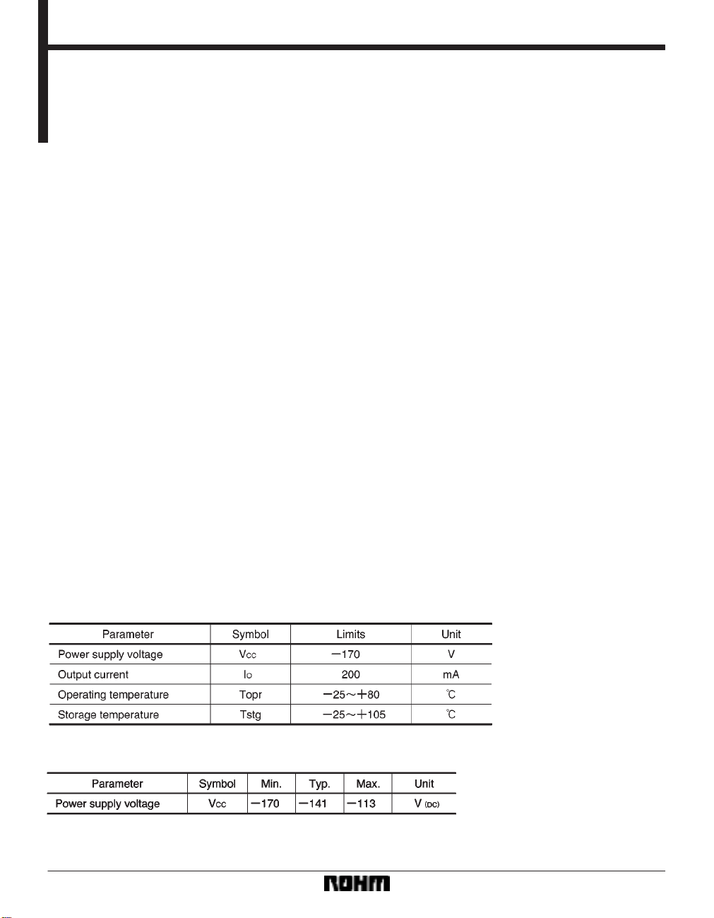
Absolute maximum ratings (Ta = 25C)
Recommended operating conditions (Ta = 25C)
344
Page 2
Regulator ICs BP5035
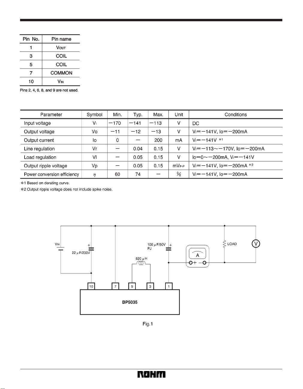
Pin descriptions
Electrical characteristics (Unless otherwise noted, Ta = 25C)
Measurement circuit
345
Page 3

Regulator ICs BP5035
Application example
Example showing BP5035 used in washing machine
Basic power supply circuit
346
Page 4

Regulator ICs BP5035
Selecting attached components
(1) Diodes
The rectifying diodes used should fulfill the following
conditions.
In the absolute maximum ratings, the reverse surge current should be 400V or higher, the average rectifying current should be 0.5A or higher, and the forward surge voltage should be 20A or higher.
(2) Capacitor for input voltage smoothing
A capacitor with a larger capacitance produces a more
stable output voltage, but increases the surge current
when the power supply is turned on. The capacitor
should have a withstand resistance of at least 200V.
Make sure a capacitor of 22µF or higher is used for half
wave rectification, and 6.8µF or higher for full wave rectification.
Operation notes
(1) The output current needs to be reduced as the ambient temperature rises.
(2) Lead pins should be securely soldered. If COMMON pins are not securely connected, or pins which are
connected internally but which are not used are connected to other pins, irregular voltages could be produced, causing breakdowns and damage.
(3) Excessive current and shorted loads
The excessive current limit is a drooping model. At 25C,
if excessive current which exceeds the absolute maximum ratings is produced intermittently, or is produced
continuously for a total of one minute or longer , the product is vulnerable to damage. If there is any danger of the
load being shorted or excessive current being produced,
always use a protective device such as a fuse.
(4) Avoid subjecting this product to strong impact.
(5) Regulations governing electrical products
As a stand-alone product, this product is not subject to
regulations governing electrical appliances. Please be
aware, therefore, that applications must be submitted for
sets and not for individual products.
(3) Capacitor for output voltage smoothing
This capacitor should have a low ESR. Capacitors designed for low-impedance switching power supplies are
especially suitable. The ESR of the capacitor affects the
output ripple voltage. Please refer to the table below for
the names of products made by various manufacturers.
(6) Insulation
This product is not insulated on the primary and secondary sides, and there is a danger of electrical shock if it is
touched.
(7) Connections with other devices
Devices using this product should not be connected to
other devices. If connected, insulation should be provided.
347
Page 5

Regulator ICs BP5035
Electrical characteristic curves
External dimensions (Units: mm)
348
 Loading...