

Page 1
Surface Mount Schottky Barrier Diodes Arrays
* Extremely Fast Switching Speed.
* Low Forward Voltage.
* Very Small Conduction Losses.
* PN Junction Guard Ring for Transient and ESD Protection.
Mechanical Data:
* Case: SOT-363, Molded plastic.
Features:
WEITRON
WEITRON
SMALL SIGNAL
SCHOTTKY DIODES
200m AMPERES
30 VOLTS
hpp://www.weitron.com.tw
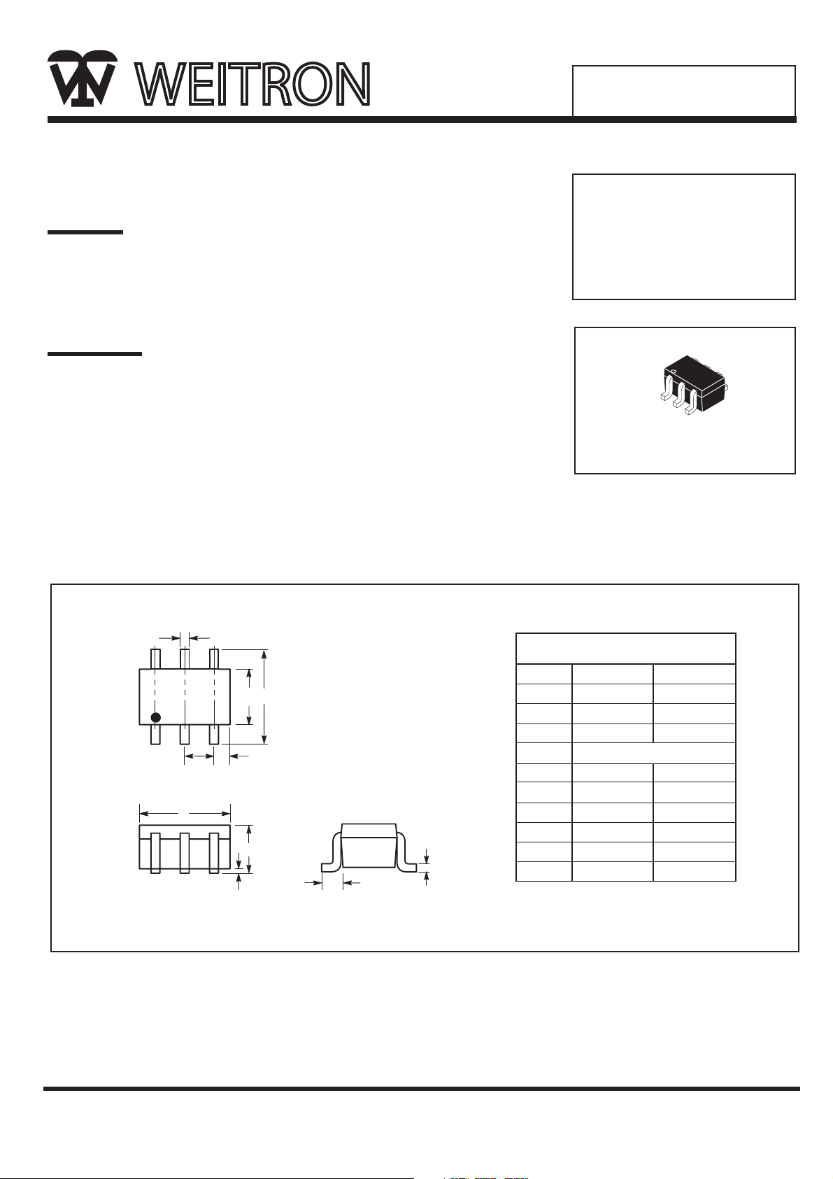
SOT-363(SC-88)
1
2
3
6
5
4
* Terminals: Solderable per MIL-STD-202, Method 208.
* Marking: See Diagrams Below & Page 3.
* Weight: 0.006 grams(approx).
SOT-363 Outline Dimensions
Unit:mm
1 2 3
A
K
J
M
L
6 5 4
B
D
H
E
C
Dim
A
B
C
D
E
H
J
K
L
M
Min
0.10
1.15
2.00
0.30
1.80
-
0.80
0.25
0.10
0.65 REF
Max
0.30
1.35
2.20
0.40
2.20
0.10
1.10
0.40
0.25
SOT-363
1/4
25-Feb-2011
BAT54TDW/BAT54CDW
BAT54BRW
BAT54ADW/BAT54SDW
Page 2

WEITRON
Maximum Ratings (T
A
=25 C Unless otherwise noted)
Characteristic
Average Rectifier
Forward Current
Peak Repetitive
Forward Current
Rated VR, Square Wave,20KHz
Operating Junction
Temperature Range
Storage Temperature Range
Symbol
I
F(AV)
I
FRM
V
RRM
V
RMW
V
R
I
FSM
T
J
T
stg
Value
Unit
200
300
125
-55 to +150
mA
mA
mA
C
C
C/W
Electrical Characteristics (T
A
=25 C Unless otherwise noted)
Characteristic
Symbol
Reverse Breakdown Voltage (IR=10µA)
Forward Voltage
IF=1.0mA
IF=10mA
IF=30mA
IF=100mA
Total Capacitance
(VR=1.0V, f=1.0MHz)
Reverse Leakage
VR=25V
Reverse Recover Time
IF=IR =10mA, I
R(Rec)
=0.1xI
R, RL Ω
V
(BR)R
V
F
C
T
I
R
Trr
Min
Typ
Max
Unit
30
0.32
0.40
0.50
1.00
10
2.0
5.0
Volts
Volts
P
F
uAdc
nS
Non-Repetitive
Forward Current(t 1.0s)
600
Peak Repetitive Reverse Voltage
Working Peak Reverse Voltage
DC Blocking Voltage
30 V
Power Dissipation
Pd
200
mw
Thermal Resistance, Junction to
Ambient Air
R
JA
500
WEITRON
2/4
25-Feb-2011
BAT54TDW/BAT54CDW
BAT54BRW
BAT54ADW/BAT54SDW
Page 3

WEITRON
BAT54TDW/BAT54CDW
BAT54BRW
BAT54ADW/BAT54SDW
http://www.weitron.com.tw
+10V
820
2.0K
100 µH
0.1µF
50 OUTPUT
PULSE
GENERATOR
50 INPUT
SAMPLING
OSCILLOSCOPE
I
F
D.U.T.
0.1µF
V
R
INPUT SIGNAL
t
r
t
p
10%
90%
t
I
F
I
R
t
rr
t
I
R(REC)
=1.0mA
OUTPUT PULSE
(IF=IR=10mA, MEASURED
AT I
R(REC)
=1.0mA)
Notes:1. A 2.0 k variable resistor for a Forward Current (IF) 0f 10 mA
2. Input pules is adjusted so IR(peak) is equal to 10 mA
3. tp t
rr
»
Device Marking
Item
Marking
Eqivalent Circuit diagram
6
1
5
2
4
3
6
1
3
5
4
2
6
1
3
5
4
2
2
3
5
4
1 6
2
1 6
3
5
4
BAT54TDW
BAT54ADW
BAT54BRW
KLB
BAT54CDW
BAT54SDW
KL6
KL7
KL8
KLA
FIG.1 Recovery Time Equivalent Test Circuit
WEITRON
3/4
25-Feb-2011
Page 4

4/4
BAT54TDW/BAT54CDW
BAT54ADW/BAT54SDW
BAT54BRW
WEITRON
100
10
125 C
1.0
FORWARD CURRENT (mA)
F,
I
0.1
0.0 0.1 0.2 0.3 0.4 0.5 0.6
150 C
25 C
85 C
VF, FORWARD VOLTAGE (VOLTS)
-40 C
-55 C
FIG.2 Forward Voltage
14
F)
p
12
10
8
6
1000
TA=150 C
100
10
1.0
0.1
, REVERSE CURRENT (µA)
0.01
R
I
0.001
0 5 10 15 20 25 30
VR,REVERSE VOLTAGE (VOLTS)
FIG.3 Leakage Current
TA=125 C
TA=85 C
TA=25 C
4
,TOTAL CAPACITANCE (
T
2
C
0
0 5 10 15 20 25 30
VR,REVERSE VOLTAGE (VOLTS)
FIG.4 Toral Capacitance
WEITRON
http://www.weitron.com.tw
25-Feb-2011
Page 5

 Loading...