

Page 1
RECTRON
SEMICONDUCTOR
TECHNICAL SPECIFICATION
FEATURES
Power Dissipation
*
PD : 200mW(Tamb= 25OC)
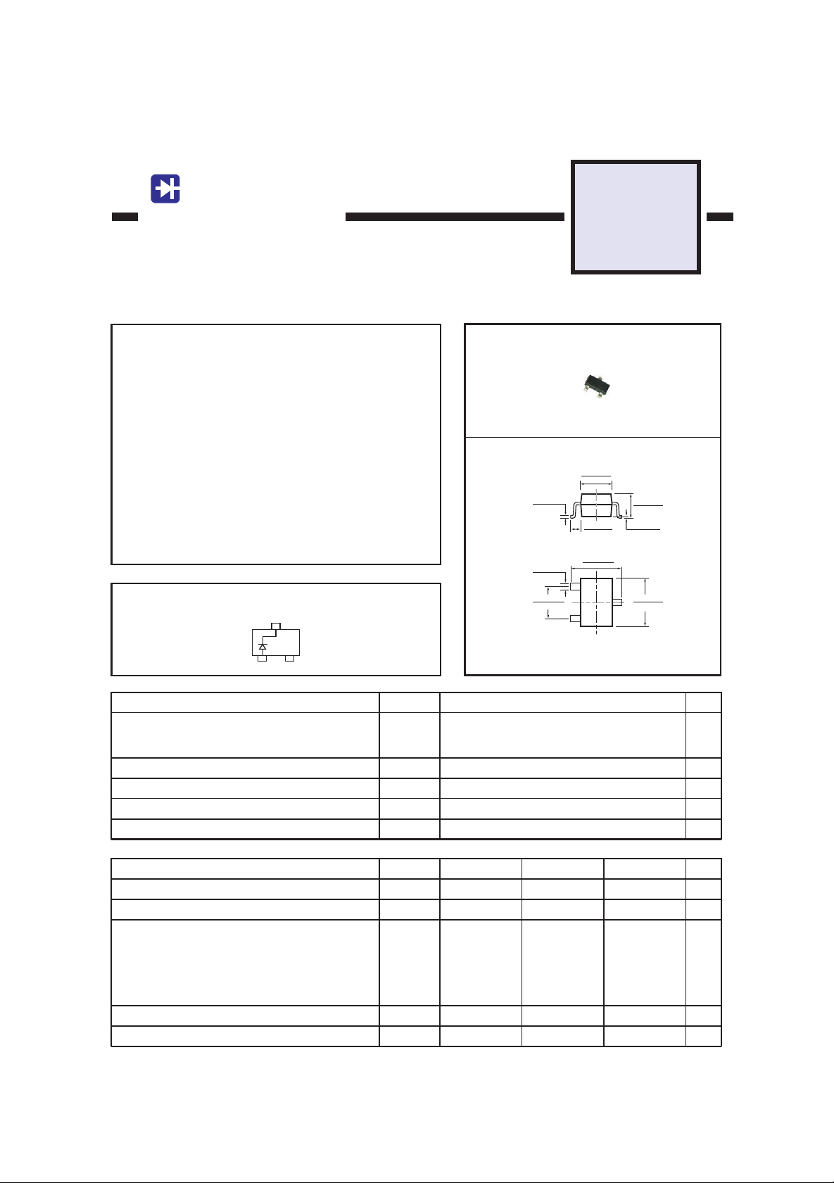
BAT54
SOT-23 SCHOTTKY DIODE
SOT-23
MECHANICAL DATA
* Case: Molded plastic
* Epoxy: UL 94V-O rate flame retardant
* Lead: MIL-STD-202E method 208C guaranteed
* Mounting position: Any
* Weight: 0.008 gram
MAXIMUM RATINGS AND ELECTRICAL CHARACTERISTICS
Ratings at 25OC ambient temperature unless otherwise specified.
MAXIMUM RATINGES ( @ TA = 25oC unless otherwise noted )
RATINGS
Peak Repetitive Peak reverse voltage
Working Peak Reverse Voltage
DC Blocking Voltage
Forward Continuous Current
Max. Steady State Power Dissipation @TA=25oC
Max. Operating Temperature Range
Storage Temperature Range
ELECTRICAL CHARACTERISTICS ( @ TA = 25oC unless otherwise noted )
CHARACTERISTICS SYMBOL UNITS
Reverse breakdown voltage (IR=100µA)
Reverse voltage leakage current (VR=25V)
Forward voltage (IF=0.1mA)
(IF=1mA)
(IF=10mA)
(IF=30mA)
(IF=100mA)
Diode capacitance (VR=1V,f=1MHz)
Reveres recovery time (IF=IR=10mA,Irr=0.1 X IR, RL=100Ω)
SYMBOL
TSTG
V
V
R
I
F
PD
TJ
(BR)R
I
R
V
F
C
D
t
rr
MIN.
30
0.006(0.15)
0.003(0.08)
0.020(0.50)
0.012(0.30)
0.019(2.00)
0.071(1.80)
Dimensions in inches and (millimeters)
VALUE
30
200
150
-55 to +150
TYP.
-
-
-
-
-
-
-
-
-
0.055(1.40)
0.047(1.20)
0.020(0.50)
0.012(0.30)
0.100(2.55)
0.089(2.25)
0.043(1.10)
0.035(0.90)
0.004(0.10)
0.000(0.00)
0.118(3.00)
0.110(2.80)
MAX.
2
0.24
0.32
0.40
0.50
1
10
5
UNITS
V
mA
mW200
o
C
o
C
V
µA
V
pF
nS
2006-3
Page 2
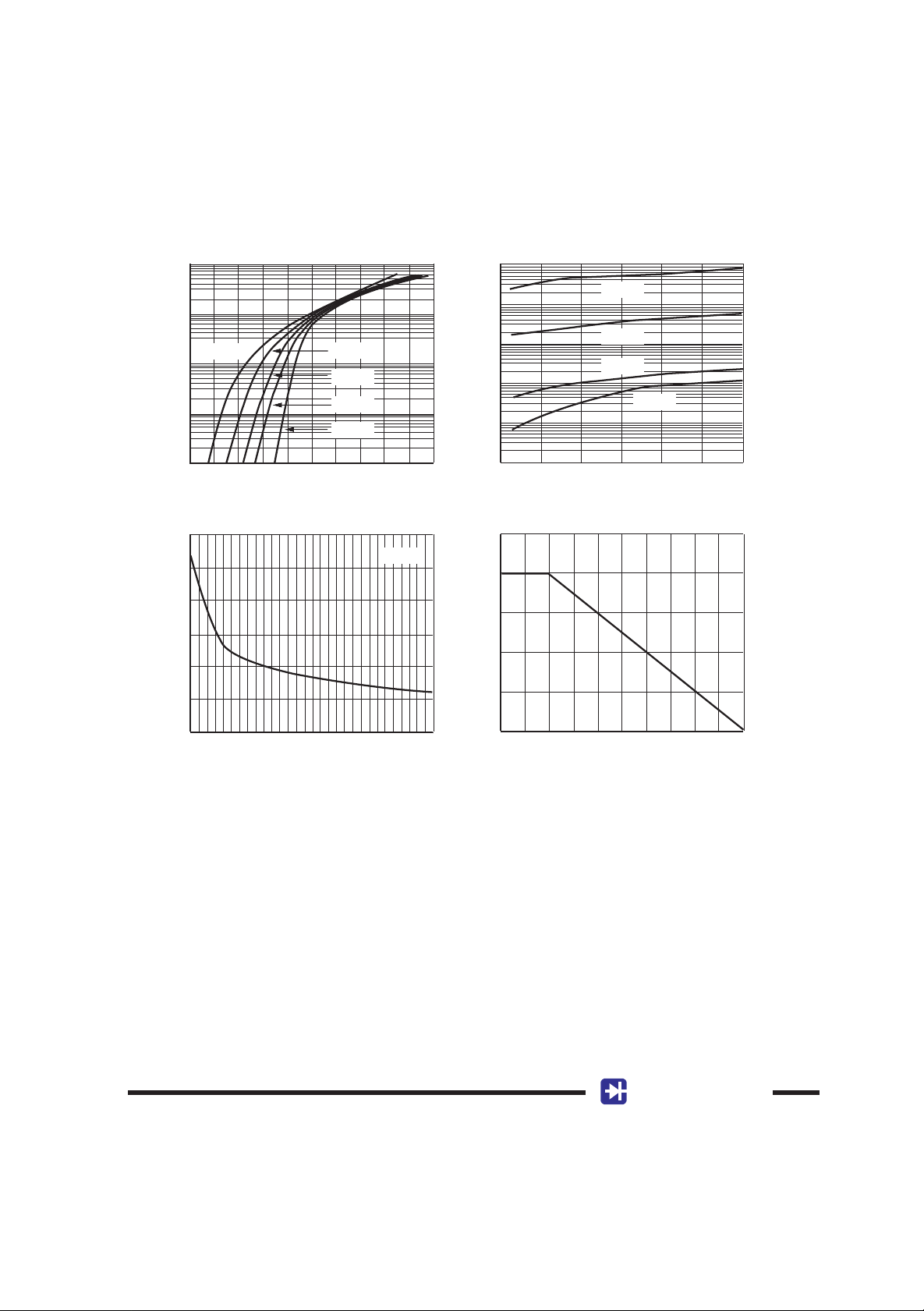
RATING AND CHARACTERISTICS CURVES ( BAT54)
1
0.1
TA= 125OC
0.01
0.001
0.0001
,INSTANTANEOUS FORWARD CURRENT(A)
0 0.2 0.4 0.6 0.8 1.0
F
I
VF,INSTANTANEOUS FORWARD VOLTAGE(V) VR,INSTANTANEOUS REVERSE VOLTAGE(V)
TA= 75OC
TA= 25OC
TA= 0OC
TA=-40OC
100
TA= 125OC
10
1
0.1
0.01
0.001
,INSTANTANEOUS REVERSE CURRENT(µA)
0 5 10 15 20 25 30
R
I
TA= 75OC
TA= 25OC
TA= 0OC
Figure1 Forward Characteristics Figure2 Typical Reverse Capacitance
12
10
8
6
4
,TOTAL CAPACITANCE(pF)
T
2
C
0
0 5 10 15 20 25 30
VR,REVERSE VOLTAGE(V) TA,AMBIENT TEMPERATURE(OC)
f=1.0MHz
200
100
,POWER DISSIPATION(mW)
D
P
0
0 25 50 75 100 125
Figure3 Typical Capacitance vs Reverse Voltage Figure4 Power Derating Curve
RECTRON
Page 3

DISCLAIMER NOTICE
Rectron Inc reserves the right to make changes without notice to any product
specification herein, to make corrections, modifications, enhancements or other
changes. Rectron Inc or anyone on its behalf assumes no responsibility or liabi lity for any errors or inaccuracies. Data sheet specifications and its information
contained are intended to provide a product description only. "Typical" paramet ers which may be included on RECTRON data sheets and/ or specifications ca n and do vary in different applications and actual performance may vary over ti me. Rectron Inc does not assume any liability arising out of the application or
use of any product or circuit.
Rectron products are not designed, intended or authorized for use in medical,
life-saving implant or other applications intended for life-sustaining or other rela ted applications where a failure or malfunction of component or circuitry may di rectly or indirectly cause injury or threaten a life without expressed written appr oval of Rectron Inc. Customers using or selling Rectron components for use in
such applications do so at their own risk and shall agree to fully indemnify Rect ron Inc and its subsidiaries harmless against all claims, damages and expendit ures.
RECTRON
Page 4

 Loading...