

Page 1
BA9700A / BA9700AF / BA9700AFV
Regulator ICs
Switching regulator for DC / DC
Converters
BA9700A / BA9700AF / BA9700AFV
The BA9700A, BA9700AF and BA9700AFV are switching regulators that use a pulse width modulation (PWM) system.
They use a transistor switch to stabilize the output voltage.
By the use of the transistor, power loss is decreased, fluctuation efficiency is improved, and the circuit is made more
compact and single.
Features
!!!!
1) Output voltage can step up, step down, or invert at an
arbitrary level.
2) Low current consumption. (typically 1.7mA)
3) Wide oscillation frequency range.
(typically 2.8k ~ 470kHz)
4) Built-in reference voltage current. (typically 2.57V)
5) Operates at low voltage. (minimally 3.55V)
6) Dead time controller restricts operation when
overloaded.
7) Power switch can isolate all circuits in the IC.
8) Best suited for battery operated equipment.
9) Compact 14-pin SSOP package (BA9700AFV).
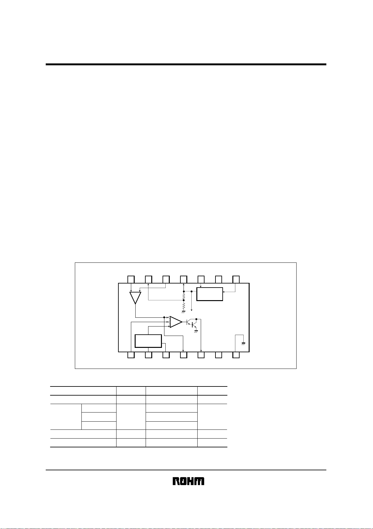
Block diagram
!!!!
NON
INVERT
1/2 V
INPUT
14 13 12 11 10 9 8
+ −
Error
Amp
Triangle
Oscillator
1234567
R
Absolute maximum ratings
!!!!
D - TIME
CONT
(Ta = 25°C)
Parameter Symbol Limits Unit
Power supply voltage
CC
V
BA9700A
Power
dissipation
BA9700AF 350
Pd
BA9700AFV 350
Operating temperature
Storage temperature
1 BA9700A: Reduced by 4.8 mW for each increase in Ta of
*
2 BA9700AF: Reduced by 4.4 mW for each increase in Ta of
*
3 BA9700AFV : Reduced by 3.5 mW for each increase in Ta of
*
3 When mounted on a 5.0´5.0´1.6 mm glass epoxy board.
*2,*
Topr -20~+80 °C
Tstg -55~+150 °C
INVERT
ref
INPUT
T
1˚C over 25˚C.
1˚C over 25˚C.
1˚C over 25˚C.
POWER
SW
V
ref
30k
30k
PWM
Comparator
T
FEED
BACK
ref
V
24 V
1
*
600
2
*
3
*
Voltage
Regulator
mW
N. C.
BA9700A
BA9700AF
N. C.OUTC
V
GND
CC
Page 2
Regulator ICs
Electrical characteristics
!
BA9700A / BA9700AF / BA9700AFV
(unless otherwise noted, Ta = 25°C, VCC = 5.0V, Rt = 10kΩ, and Ct = 330pF)
Parameter Min. Typ. Max. Unit Conditions
〈Reference voltage section〉
Output voltage
ref
1/2 V output voltage
Line regulation
Load regulation 1
Load regulation 2
Output voltage when power decreases
Output current when short-circuited
〈Triangular wave oscillation section〉
Oscillation frequency
Standard deviation of
oscillation frequency
Frequency variation (V )
〈Error amplifier section〉
CC
Input offset voltage
Input offset current
Maximum input voltage
Open loop gain
Common-mode rejection ratio
Input bias current
〈PWM comparator section〉
Threshold voltage 1
Threshold voltage 2
〈Output section〉
Output transistor leakage current
Output saturation voltage
〈Total device〉
Quiescent current
Standby current
Operating voltage
Symbol
V
ref
1/2 V
Line
Load1
Load2
ref
V
Iosc
fosc
fosc
fdv
IO
V
I
IO
V
ICR
A
V
CMRR
IB
I
V
t0
V
t100
Leak
Vsat
CC
I
I
CCS
V
CC
2.48 2.57 2.66 V I
ref
1.22 1.29 1.36 V
- 3.00 12.0 mV V
- 1.00 5.00 mV I
- 6.00 10.0 mV I
2.48 2.57 2.66 V
- 10.0 30.0 mA V
- 230 - kHz
-10-%
-1-%
-6.0 - mV
-100 - nA
6.0
100
1.60 1.90 - V
70.0 80.0 - dB
70.0 80.0 - dB
- 180 500 nA
- 2.04 2.24 V
1.25 1.43 - V
- - 10.0 µA
- 1.70 2.10 V
- 1.70 2.40 mA
- 0 7.00 µA
3.55 - 24.0 V
ref
= 0.1mA
CC
= 3.55V~24V
ref
= 0.1mA~1.0mA
ref
= 0.1mA~8.0mA
I
ref
= 0.1mA, VCC = 3.55V
ref
= 0V
T
= 10kΩ, CT = 330pF
R
T
R and C are constant
V
T
CC
= 3.55~24V
Null Method
Null Method
Null Method
Null Method
Null Method
Null Method
DUTY 0%
DUTY 100%
V
O
= 24V
I
O
= 50mA
T
= OPEN POWER SW = 2.5V
R
POWER SW = 0V
Page 3
Regulator ICs
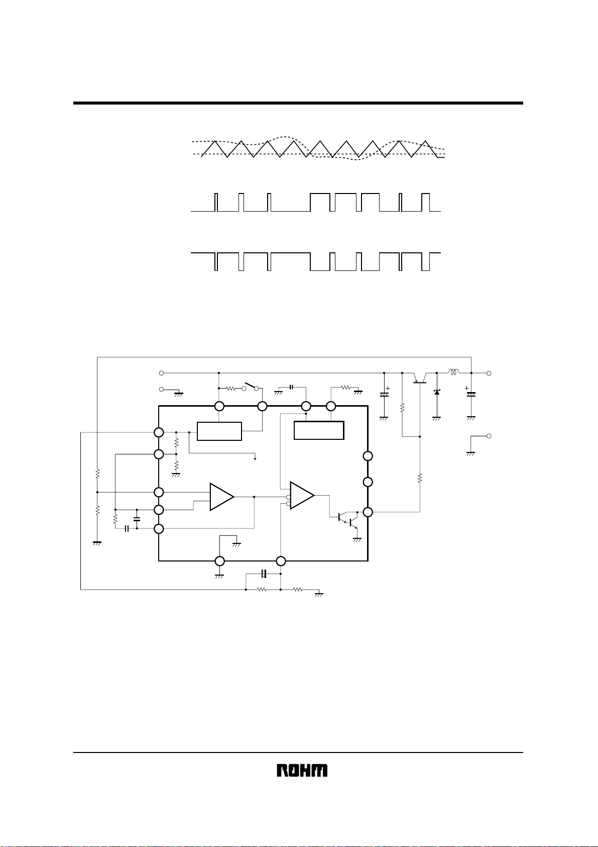
Timing chart
!!!!
ERR. AMP
OUTPUT
DEAD - TIME
PWM. COMP
OUTPUT
BA9700A / BA9700AF / BA9700AFV
H
L
OUTPUT TR.
COLLECTOR
Application examples
!!!!
V
GND
R
1
43k
1
C
7.5k
680p
R
3
C
2
0.047µ
15k
2
R
H
L
Fig.1
L
6
120µH
RB100A
D
1
1
N.C.
N.C.
Q12SB1009
C
8
7
R
560
R
560
IN
2.57V
11
30k
13
1.29V
30k
14
12
4
Voltage
Regulator
ERROR AMP
+
−
47k
SW
9
R
V
ref
C
1
PWM COMPARATOR
9
1000p
3108
Triangle
Oscillator
R815k
470µ
2
9
6
5
C5, C
470µF
×
5V
OUT
V
6
2
GND
17
C4 1µ
+
5
4
15k
20kR
R
Fig.2 Step-down converter
L1: RCH-875 121K (Sumida Electronics)
Page 4

Regulator ICs
BA9700A / BA9700AF / BA9700AFV
39k
4.7k
330
R
RB100A
L
1
220µH
D
1
C
470µ
×2
4, C5
V
OUT
GND
6
R
33k
R
6.8k
IN
V
R
Voltage
Regulator
47k
9
V
ref
GND
2.57V
11
30k
13
1.29V
1
30k
ERROR AMP
14
C
1
R
2
3
7.5k
0.047µ
C
12
680p
4
2
+
−
SW
C3 1µ
1
C7 1000p
3108
Triangle
Oscillator
PWM COMPARATOR
17
R
5
39kR4 22k
R810k
2
9
6
5
Q12SB1009
330
R
7
C
6
470µ
L1: RCH-875 220K (Sumida Electronics)
Fig.3 Inverting converter
L
1
R
470
RB100A
D
22µH
1
R
8
68
Q
2
2SD1380
7
V
IN
GND
2.57V
11
Voltage
Regulator
30k
13
1.29V
1
C
680p
30k
ERROR AMP
14
12
+
−
4
R
1
2
R
R
3
7.5k
C
2
0.047µ
47k
SW
11
R
V
ref
C
1
108
PWM COMPARATOR
8
1000p
3
Triangle
Oscillator
R1010k
2
100µ
C
7
R
9
470
Q
2SB1009
9
R
6
6
470
5
12V
V
C
470µ
×2
OUT
5, C6
GND
1
17
C4 1µ
5
39kR4 20k
R
Fig.4 Step-up converter
L1: RCH-875 221K (Sumida Electronics)
Page 5

BA9700A / BA9700AF / BA9700AFV
Regulator ICs
Basic application board patterns and component arrangemrnts
!!!!
V
IN
GND
Fig.5 Step-down converter
IN
V
GND
2
C
R
10
3
C
1
BA9700A
R
9
Q
1
B
SW
R
+
C
7
E
C
8
D
C11C
R
4
()()
R
6
+
R
1
+
L
+
C
7
4
R
2
+
C
5
V
OUT
GND
C
6
R5R
C9C
8
3
C
BA9700A - 1
C
C
2
R
2
C
1
7
BA9700A
SW
R
3
R
9
1
Q
B
+
C
E
C
6
R
5
C
R
8
3
R
4
+
R
R
1
6
5
C
L
+
OUT
V
C
4
GND
D
1
BA9700A - 2
Fig.6 Inverting converter (BA9700A)
IN
V
SW
GND
Fig.7 Step-up converter (BA9700A)
C4C
3
C
2
R
3
C
1
BA9700A
R
11
R
9
+
C
7
R10R
5
R
4
R
6
C
6
R
2
+
R
1
R
8
Q
1
Q
2
R
7
B
C
E
+
B
C
E
L
C
5
V
OUT
GND
Page 6

Regulator ICs
Electrical characteristic curves
!!!!
1M
100k
(Hz)
10k
FREQUENCY
1k
1k 10k 100k 1M
Fig.8 Oscillation frequency
characteristic vs. triangular
wave oscillator resistance (1)
80
300
60
(d B)
(DEG)
200
40
100
20
PHASE
G A I N
0
0
-100
-20
-200
-40
0 100 1k 10k 100k 1M 10M
Fig.11 Phase and gain vs. frequency
for the error amplifier
CT = 220pF
CT = 2200pF
CT = 0.022µF
RT (Ω)
FREQUENCY
(Hz)
BA9700A / BA9700AF / BA9700AFV
1M
R
T
R
T
CT
= 10kΩ
= 30kΩ
(F)
100k
(Hz)
10k
FREQUENCY
1k
100p 0.01µ 0.1µ1000p
Fig.9 Oscillation frequency
characteristic vs. triangular
wave oscillator resistance (2)
R
T
= 20kΩ
4.00
3.50
3.00
2.50
2.00
(VOLTAGE)
1.50
Vref
1.00
0.50
0.00
510152025
(V)
V
CC
Fig.10 Output voltage vs. operating
voltage for the reference
voltage section
Page 7

BA9700A / BA9700AF / BA9700AFV
Regulator ICs
External dimensions
!!!!
BA9700A BA9700AF
14 8
0.51Min.
3.2±0.2 4.25±0.3
BA9700AFV
0.2
±
4.4
6.4±0.3
0.1
±
0.1
1.15
0.65
19.4±0.3
2.54
5.0±0.2
14
1
(Units : mm)
71
0.5±0.1
8
7
0.22±0.1
6.5±0.3
0.3Min.
7.62
0°∼15°
0.1
±
0.15
0.3±0.1
0.1
8.7±0.2
14
0.2
±
4.4
6.2±0.3
1
1.5±0.1
0.11
8
7
0.15±0.1
0.4±0.11.27
0.3Min.
0.15
SOP14DIP14
SSOP - B14
 Loading...