

Page 1
1
Multimedia ICs
Microphone Amplifier
BA7760 / BA7760F
The BA7760 and BA7760F are dual microphone amplifiers designed for audio signal amplification. These are low
noise amplifiers with a low -122dBV (typically) equivalent input noise voltage. Each IC has an internal mixer buffer
amplifier for the mixing of signals from two channels. When used with the BA7725S or BA7725FS, the BA7726AS or
BA7726AFS and BU9252S or BU9252F, these ICs simplify the configuration of digital echo systems with two inputs
(for karaoke duets, for instance).
•
Features
1) Internal 2-channel low noise microphone amplifier.
2) Internal mixer buffer amplifier with mute function.
3) Available in 2 types of packages: DIP 14-pin or SOP
14-pin.
•
Applications
Audio equipment with karaoke features, VCRs, LDs, etc.
•
Absolute maximum ratings (Ta = 25°C)
Parameter Symbol Limits Unit
Applied voltage 15 V
BA7760
mW
BA7760F
Operating temperature °C
Storage temperature °C
V
CC
Power
dissipation
600
∗
1
450
∗
2
Pd
Topr – 25 ~ + 75
– 55 ~ + 125Tstg
∗
1 Unmounted. Reduced by – 6.0mW for each increase in Ta of 1°C over 25°C.
∗
2 Unmounted. Reduced by – 4.5mW for each increase in Ta of 1°C over 25°C.
•
Recommended operating conditions
Parameter Symbol Limits Unit
Power supply voltage V
CC 6 ~ 14 V
Page 2
2
Multimedia ICs BA7760 / BA7760F
•
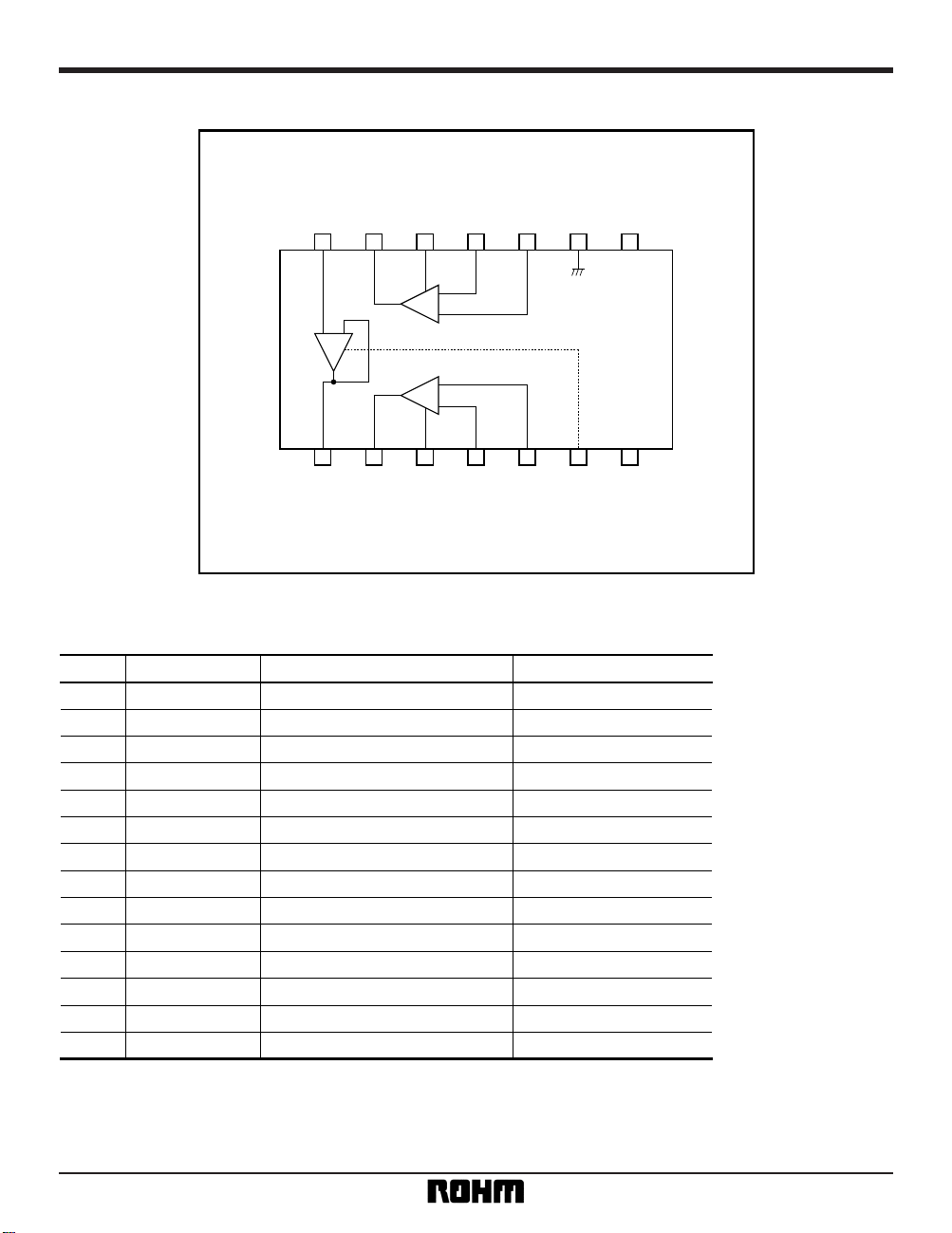
Pin descriptions
Pin name Pin type
1 Ripple filter
2GND GND —
3 MIC IN ( + ) Ch1 CH1 microphone amplifier input ( + )
4 MIC IN ( – ) Ch1 CH1 microphone amplifier input ( – ) Base (NPN)
5 CH1 microphone amplifier fc Base (NPN) ~ 450Ω
6 CH1 microphone amplifier output Push-pull
7 Mixer buffer input
8 Mixer buffer output Push-pull
9 CH2 microphone amplifier output Push-pull
10 CH2 microphone amplifier fc Base (NPN) ~ 450Ω
11 MIC IN ( + ) Ch2 CH2 microphone amplifier input ( – ) Base (NPN)
12 MIC IN ( – ) Ch2 CH2 microphone amplifier input ( + )
13 Mute control Fig.1
14 —
RIPPLE FILTER
FILTER Ch1
MIX IN
MIC OUT Ch1
MIX OUT
MIC OUT Ch2
FILTER Ch2
MUTE CTRL
V
CC VCC
Base (NPN) // 15kΩ
Base (NPN) // 120kΩ
Base (NPN) // 65kΩ
Base (NPN) // 120kΩ
Pin No. Function
∗
“Parallel” and “series” respectively refer to parallel and series insertion. All figures are standard values.
•
Block diagram
+
–
–
+
–
+
8
9
10
11
12
13
14 1
2
3
4
5
6
7
GND
MIX IN
MIC OUT Ch1
FILTER Ch1
RIPPLE FILTER
MIX OUT
MUTE CTRL
V
CC
MIC IN Ch1 ( – )
MIC IN Ch1 ( + )
MIC AMP CH 1
MIC AMP CH 2
MIX BF
MIC OUT Ch2
FILTER Ch2
MIC IN Ch2 ( + )
MIC IN Ch2 ( – )
Page 3

3
Multimedia ICs BA7760 / BA7760F
•
Electrical characteristics (unless otherwise noted, Vcc = 12V, Ta = 25°C)
Parameter Symbol Min. Typ. Max. Unit
Supply current I
q 3.65 4.87 6.09 mA
〈MIC AMP (GVC = 36dB, f = 1kHz)〉
55.0 65.0 — dB VIN = – 70dBV
— – 122 – 114 dBV Rg = 2.2kΩ, DIN AUDIO
— 0.008 0.1 %
V
IN = – 40dBV
B.W. = 0.4 ~ 30kHz
8.3 10.4 — dBV
THD = 1%
B.W. = 0.4 ~ 30kHz
92 123 — kΩ V
IN = – 40dBV, 100kΩAttenuation
V
IN = – 10dBV, 50kΩAttenuation
— – 86 – 78 dBV
V
IN = – 36dBV
R
g = 2.2kΩ, DIN AUDIO
– 0.7 0 0.7 dB V
IN = – 10dBV
— –110 – 100 dBV R
g = 2.2kΩ, DIN AUDIO
— 0.002 0.07 %
V
IN = – 10dBV
B.W. = 0.4 ~ 30kHz
8.3 10.5 — dBV
THD = 1%
B.W. = 0.4 ~ 30kHz
50.0 66.5 — kΩ
— – 110 – 100 dBV V
IN = – 10dBV, DIN AUDIO
2.12 2.62 3.12 V
VnM
THDM
VomM
ZinM
CTM
GVB
VnB
THDB
VOMB
ZinB
MTB
VTHMUTE
Open loop voltage gain
Input conversion noise
Distortion
Maximum output level
Input impedance
Crosstalk
〈MIX BF (f = 1kHz)〉
Voltage gain
Output residual noise
Distortion
Maximum output level
Input impedance
Mute level
Mute threshold voltage
Conditions
—
—
G
VOM
•
Input / output circuits
Fig. 1
40kΩ
MUTE CTRL 13
Page 4

4
Multimedia ICs BA7760 / BA7760F
•
Measurement circuit
+
–
MIX BF
8
9
10
11
12
13
14 1
2
3
4
5
6
7
–+ –+
+
4.7µF
5kΩ
2.2kΩ
150pF
13.9kΩ
1MΩ
220Ω
+
4.7µF
2.2kΩ
22µF
+
+
+
Ch1
Ch1
220Ω
2.2kΩ
4.7µF
+
+
+
150pF
13.9kΩ
1MΩ
Ch2
10kΩ
5kΩ
10µF
Ch2CTRL
MUTE
470µF
47µF
470µF
47µF
MIC IN
MIX OUT
MIC OUT
MIX IN MIC OUT
MIC IN
BA7760 / F
MIC AMP Ch2
MIC AMP Ch1
V
CC
Fig. 2
•
Circuit operation (Refer to “Application Example”)
The BA7760 and BA7760F are dual microphone amplifiers. The audio signals from the microphones are input
to pins 3 and 12. The gain at this time is determined by
attached resistors R3 / R4 and R6 / R7. By attaching
capacitors to pins 5 and 10, the microphone amplifiers
can be given frequency characteristics like those
shown below.
(Note: The attached component numbers are those used in “Application
Example.”)
60dB
40dB
20dB
0dB
– 20dB
1kHz 10kHz 100kHz 1MHz 10MHz100MHz
VOLTAGE GAIN : GV (dB)
C = 150pF
C = 0
361
163
163163163
180°
0°
– 180°
FREQUENCY : f (Hz)
PHASE
Characteristics when using standard
components and standard constants
Fig. 3 Microphone amplifier
frequency characteristics
Page 5

5
Multimedia ICs BA7760 / BA7760F
Output from these dual amplifiers is level-adjusted with
an attached volume control (VR) and then input to pin
7 and mixed by the mixer buffer amplifier. The ON /
OFF operation of the mixer buffer amplifier can be controlled with the signal input to pin 13 (MUTE CTRL).
For DC loads, this volume control (VR) should be set
above 4.5kΩ to assure proper performance of the IC’s
internal driver.
Mode Control signal Operation
MUTE L Muted
MUTE H Normal operation
•
Application example
Fig. 4
8
9
10
11
12
13
14
7
6
5
4
3
2
1
+
–
+
–
10kΩ
10µF
MIXOUT
(VR)
1µF
220Ω
47µF
150pF
12kΩ
4.7µF
2.2kΩ
MICINMUTE
CTRL
22µF
2.2kΩ
MICIN
(VR)
1µF
220Ω
47µF
150pF
R3
12kΩ
5kΩ
5kΩ
22kΩ
0.1µF
22kΩ
0.1µF
R4
4.7µF
R7
R6
+
–
MIC AMP Ch2
MIC AMP Ch1
MIX BF
Ch2
Ch1
BA7760 / F
VCC
+
+
+
+
+
+
+
+
Page 6

6
Multimedia ICs BA7760 / BA7760F
DIP14 SOP14
BA7760 BA7760F
6.5 ± 0.3
19.4 ± 0.3
0.5 ± 0.1
3.2 ± 0.2 4.25 ± 0.3
14 8
71
0.3 ± 0.1
0.51Min.
7.62
0° ~ 15°
2.54
0.4 ± 0.11.27
1
14
8.7 ± 0.2
7
8
4.4 ± 0.2
6.2 ± 0.3
0.11
1.5 ± 0.1
0.15
0.15 ± 0.1
0.3Min.
•
External dimensions (Units: mm)
 Loading...