

Page 1
1
Video ICs
High-voltage audio head selection
switch
BA7755A / BA7755AF
The standard audio circuits of video cassette recorders and the recording circuits of tape decks use AC bias recording to record the audio signal onto the tape. This bias voltage is some tens of volts, and a high-capacity bias-side
switch is required to electronically switch the head when in playback or record mode.
The BA7755A and BA7755AF are high-voltage switching ICs designed to switch voltages as high as ± 65V
DC or
AC120V
P-P (f = 70Hz).
Two control systems, one for current control, and one for voltage control are provided, so the ICs can be used in circuits that employ either method.
By combining the BA7755A or BA7755AF with the BA7751ALS recording / playback amplifier, it is possible to construct a compact recording / playback audio circuit. In addition, the BA7755A and BA7755AF are an excellent choice
for a wide variety of other high-voltage switching applications.
•
Applications
Video cassette recorders and tape decks
•
Features
1) High withstanding voltage ( ± 65V
DC (Min.),
AC120V
P-P (Min.), f = 70Hz).
2) Circuits for either current control or voltage control
are provided on the chip.
3) Compact SIP 5pin or SOP 8pin package.
•
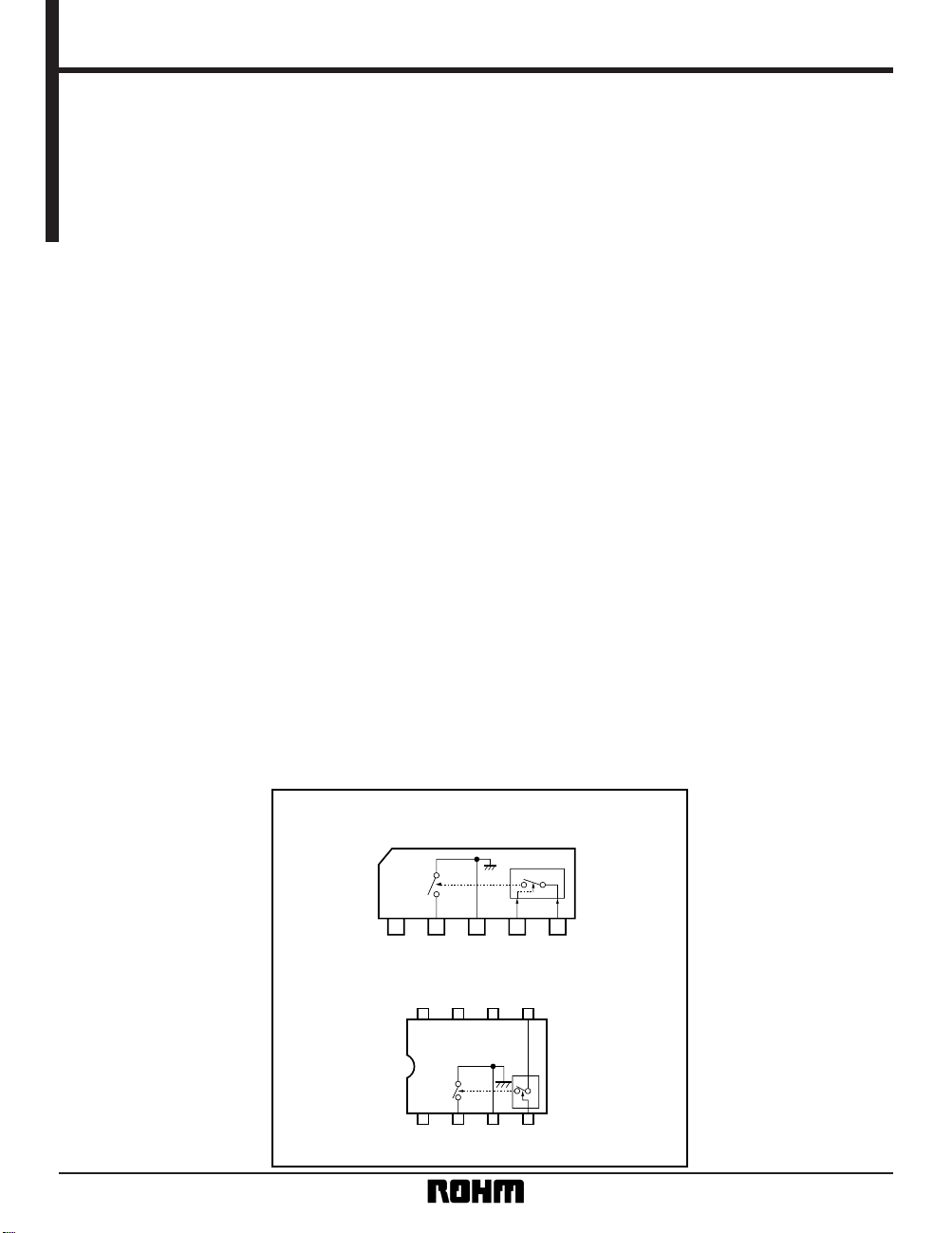
Block diagram
BA7755AF
12345
SW GND CTRL2 CTRL1
BA7755A
VCC
8765
1234
N.C. N.C. N.C.
HEAD
SWITCH
GND CTRL2
CTRL1
VCC
Page 2
2
Video ICs BA7755A / BA7755AF
•
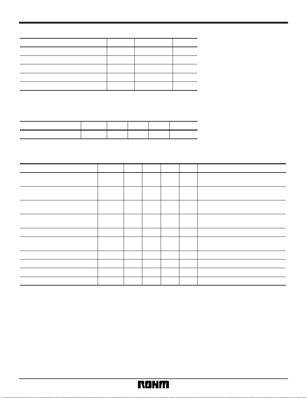
Absolute maximum ratings (Ta = 25°C)
Parameter Symbol Limits Unit
V
CC
15 V
Pd 400
∗
1
mW
Topr – 10 ~ + 65
°C
Tstg – 55 ~ + 125 °C
BV
CC2
± 65 V
∗
Reduced by 4mW for each increase in Ta of 1°C over 25°C.
Power supply voltage
Power dissipation
Operating temperature
Storage temperature
Breakdown voltage of switch (pin 2)
•
Recommended operating conditions (Ta = 25°C)
Parameter Unit
V
Max.
139
Typ.Min.
4
Symbol
V
CC
Operating voltage
•
Electrical characteristics (unless otherwise noted, Ta = 25°C and VCC = 9V)
Parameter
Symbol Min. Typ. Max. Unit
Conditions
I
CC1
—
010µA
Pin4 “L” or “OPEN”
Pin5 “OPEN”
I
CC2
2.4 3.9 5.6 mA
Pin 4 “L” or “OPEN”
Pin 5 control current: 200
µA
R
ON
—
8.0 15.0
Ω
Pin 4 “L” or “OPEN”
Pin 5 control current: 200µA
I
LOFF
—
010µA
Pin 4 “H”, or “OPEN”, or “L
”
Pin 5 “OPEN”, pin 2 applied voltage ± 65V
BV
AC
120 160
—
V
P-P
f = 70kHz
V
OS
—
4.3 15.0 mV
Pin 4 “L” or “OPEN”
Pin 5 control current: 200
µA
I
CTRL1 (ON)
50
——
µ
A
—
I
CTRL1 (OFF)
——
1
µ
A
—
V
TH1
1.70 2.15 2.60 V
—
R
CTRL2
21.0 31.0 42.0 k
Ω
—
Supply current
Supply current
Switch-on resistance
Switch leakage current
Switch AC breakdown voltage
Switch offset voltage
CTRL1 SW ON control current
CTRL1 SW OFF control current
CTRL2 threshold voltage
CTRL2 input resistance
Page 3

3
Video ICs BA7755A / BA7755AF
•
Switch control methods
(1) Control with pins 4 and 5
BA7755A
12345
SW1
SW2
5V
R
V
CC
Fig. 1
Head
SW2
OFF
ON
OFF
ON
SW1
OFF
ON
R ⱌ
–10 [kΩ]
Between pins 2 and 3
VCC – 1.4 [V]
200 [µA]
High impedance
Low impedance
High impedance
High impedance
When VCC = 9V (approx) R ⱌ 28kΩ
SW1
OFF
ON
Between pins 2 and 3
Low impedance
High impedance
(2) Control with pin 4 only
BA7755A
12345
SW1
5V
R
V
CC
Fig. 2
Head
REC / EEE
EE (L)
REC (H)
Between pins 2 and 3
Low impedance
High impedance
(3) When used with the BA7751ALS
BA7755A
12345
BA7751ALS
17
20
VCC
REC / EE
Fig. 3
Head
Page 4

4
Video ICs BA7755A / BA7755AF
•
Application example
BA7755A
12345
LINE IN
47
µ
/ 16V
2 4 6 8 10 12 14 16 18 20 22 24
1 3 5 7 9 11 13 15 17 19 21 23
100
µ
/ 16V
+
R
6
1000p
+
C
9
4.7
µ
/ 25V
R
7
56k
C
12
33
µ
/ 16V
+
10k
22k
10k
4.7
µ
/ 25V
LINE OUT
+
4.7
µ
/ 25V
+
EE EE
SP
4.7
µ
/ 25V
68k
68k
PB REC
EP
MUTE ON
MUTE OFF
BA7751ALS
BIAS
PB
SW7
SW1
R
P
ALC DET.
ALC VR.
LINE
SW2
40dB
BIAS
BUFF.
SW5
SW4
SW3
REC
SW8
4.7
µ
/ 25V
+
0.033
µ
470
L
1
3.9mH
0.047
µ
VR2
AC BIAS
51k
C
19
10µ / 16V
2.7k
47k
1M
+
47
µ
/ 16V
22
µ
/ 16V
PB IN REC OUT
+
10k
VR1
C
8
10
µ
/ 16V
18k
12k
330k
0.01
µ
220
33
µ
/ 16V
4.7
µ
/ 25V
47
1000p
1000p
VCC
CTRL VCC
C
16
C
18
R12R
10
R8
R
13
C
15
R16
C7
C6
C
10
R15
R
19
C20
R14
C21
C17
R9
C14
C13
C
4
C5
R4
R
1
C
1
R2
R3
R5
C2
C3
+
+
+
+
+
5.6 k
–
26dB
R / P HEAD
Fig.4
Note:
R
13, C16, R16 and C18 prevent switching
noise. These are not required if external
muting or some other method is used to
eliminate switching noise.
•
External dimensions (Units: mm)
SIP5 SOP8
BA7755A BA7755AF
0.4 ± 0.11.27
0.15
0.3Min.
0.15 ± 0.1
0.11
6.2 ± 0.3
4.4 ± 0.2
5.0 ± 0.2
85
41
1.5 ± 0.1
2.54
9.6 ± 0.5
3.5 ± 0.5
4.9
±
0.2
1.2
0.6
1
1.3
0.8
0.6
5
11.8 ± 0.2
0.3 ± 0.1
2.4 ± 0.2
 Loading...