

Page 1
Optical disc ICs
4-channel BTL driver for CD players
BA6397FP
The BA6397FP is a 4-channel BTL driver for CD player motors and actuators. The 5V regulator and internal standard
operational amplifier make this IC suited to a broad range of applications.
Applications
CD players and CD-ROM drives
Features
1) HSOP 28-pin package allows for miniaturization of
applications.
2) Low number of external components.
3) Driver gain is adjustable with a single attached resistor.
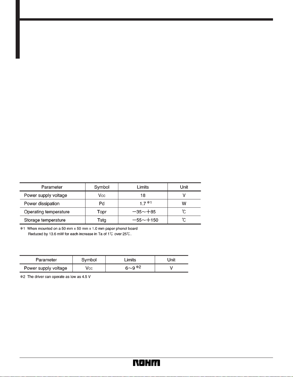
Absolute maximum ratings (Ta = 25C)
4) Internal 5V regulator. (requires attached PNP transistor)
5) Internal standard operational amplifier.
6) Internal thermal shutdown circuit.
Recommended operating conditions (Ta = 25C)
332
Page 2
Optical disc ICs BA6397FP
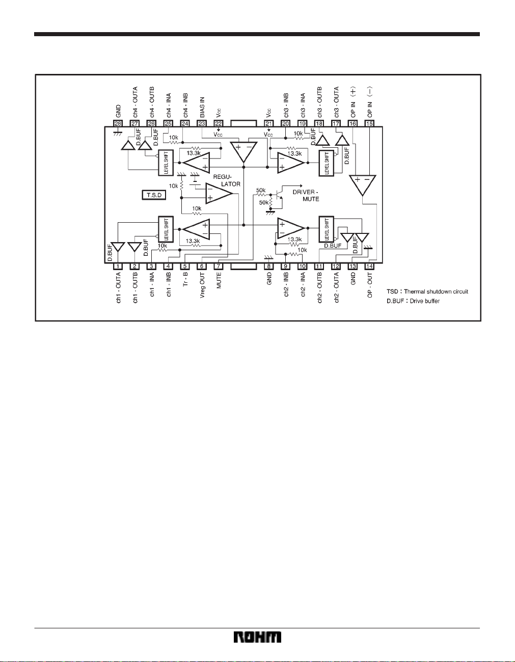
Block diagram
333
Page 3
Optical disc ICs BA6397FP
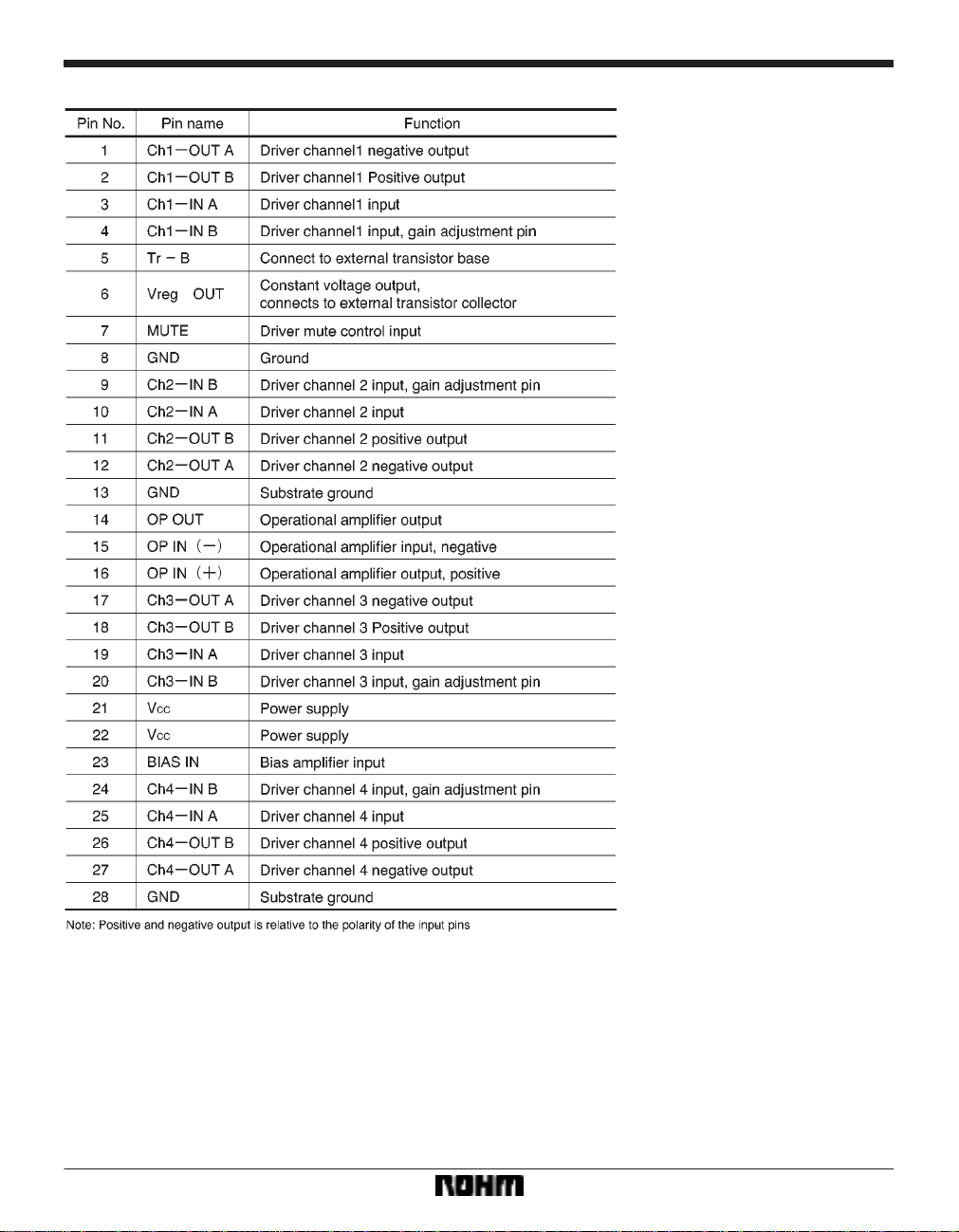
Pin descriptions
334
Page 4

Optical disc ICs BA6397FP
Input/output circuits
335
Page 5

Optical disc ICs BA6397FP
Electrical characteristics (unless otherwise noted, Ta = 25C, VCC = 8V, f = 1kHz, RL = 8Ω)
Circuit operation
(1) Driver
Inputs to the IC are the focus tracking error signal from
the servo preamplifier and the control signal from the motor. The input signals, which normally center on 2.5V , are
V /I converted by the preamplifier, generating a current
corresponding to the input voltage. This current is
336
passed through a resistor and into the internal reference
voltage component, the preamplifier output being a signal centering on the internal reference voltage. Two systems (positive phase and negative phase) are created
during V /I conversion, generating BTL output via the
driver buffer.
Page 6

Optical disc ICs BA6397FP
(2) Regulator
This is a typical series regulator that generates a reference voltage internally. A PNP low saturation type transistor must be connected.
(3) Operational amplifier
A standard 4558 type.
Application example
337
Page 7

Optical disc ICs BA6397FP
Operation notes
(1) The BA6397FP has an internal thermal shutdown
circuit. Output current is muted when the chip temperature exceeds 175C (typically).
(2) If the mute pin (pin 7) voltage is opened or lowered
below 0.5V , the output current will be muted. Pin 7 should
be pulled up above 2.0V during normal use.
(3) The bias pin (pin 23) is muted when lowered below
1.4V (typically). Make sure it stays above 1.6V during
normal use.
(4) Muting occurs during thermal shutdown, mute-on
operations or a drop in the bias pin voltage. In each case,
only the drivers are muted. During muting, the output pins
remain at the internal bias voltage, roughly (V
CC–VF)/2.
(5) The internal input resistor has a positive temperature coefficient of roughly 2000ppm / degree, and so
when changing the gain using an attached resistor, gain
will also change at a rate of roughly 2000ppm / degree.
There is virtually no gain variation due to temperature
when using the internal input resistor.
(6) Be sure to connect the IC to a 0.1µF bypass capacitor to the power supply, at the base of the IC.
(7) The radiating fin is connected to the package’s internal GND, but should also be connected to an external
ground.
(8) The capacitor between regulator output (pin 6) and
GND also serves to prevent oscillation of the IC, so select
one with good temperature characteristics.
Electrical characteristic curves
338
Page 8

Optical disc ICs BA6397FP
Electrical characteristic curves
External dimensions (Units: mm)
339
 Loading...