

Page 1
Optical disc ICs
2-channel BTL driver for CD players
BA6295AFP
The BA6295AFP is a 2-channel BTL driver for CD player actuators and motors. This IC delivers a large output current
and is ideal for car CD players.
FApplications
CD players
FFeatures
1) 2-channel BTL driver.
2) High output current. (Io = IA Typ.)
3) HSOP 28-pin package allows for miniaturization of
applications.
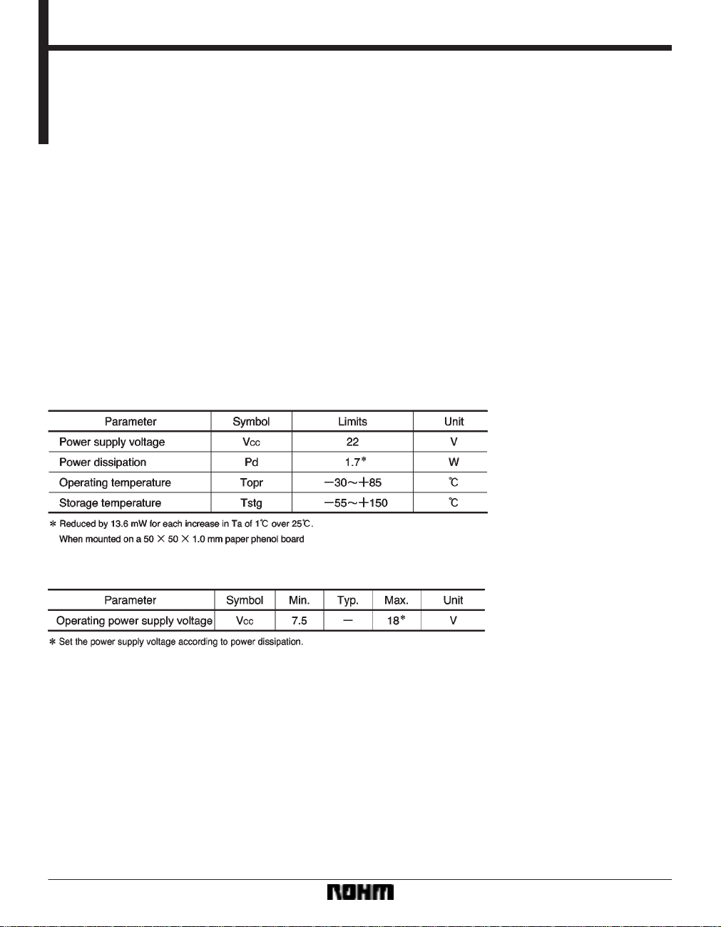
FAbsolute maximum ratings (Ta = 25_C)
4) Internal thermal shutdown.
5) Gain is adjustable by inserting a resistor between
pins 27 and 28 ; pins 18 and 16.
FRecommended operating conditions (Ta = 25_C)
197
Page 2
Optical disc ICs BA6295AFP
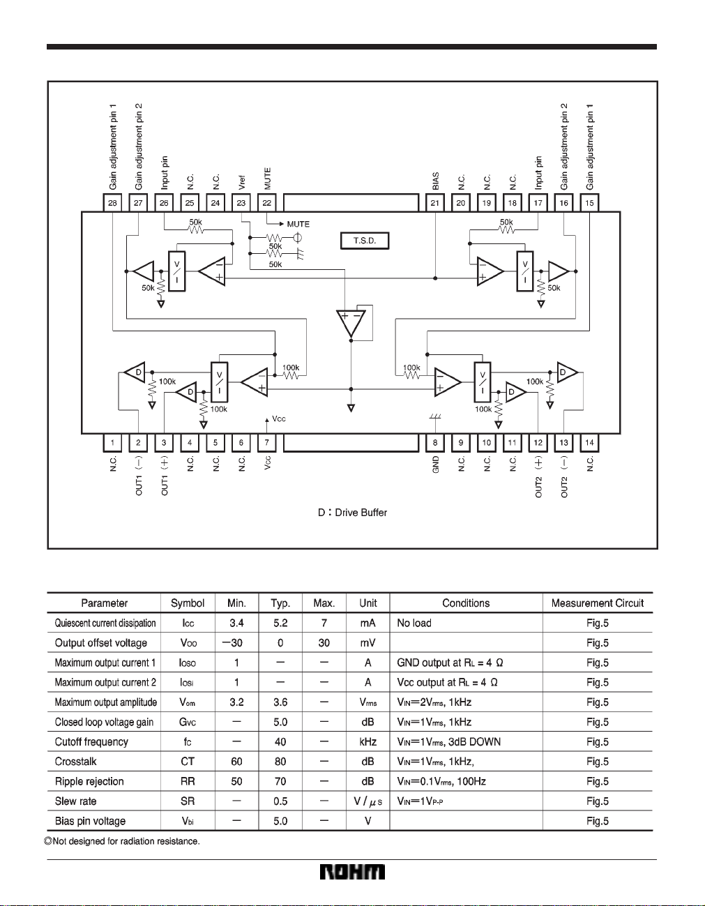
FBlock diagram
FElectrical characteristics (unless otherwise noted, Ta = 25_C, V
198
CC = 10V, f = 1kHz)
Page 3

Optical disc ICs BA6295AFP
Electrical characteristic curves
Measurement circuit
199
Page 4

Optical disc ICs BA6295AFP
FCircuit operation
The BA6295AFP comprises a 2-channel driver, internal
bias amplifier, mute pin, and thermal shutdown circuit.
(1) Driver
The input resistance of the driver is the focus tracking error signal from the servo preamplifier and the control signal from the motor. The input signals normally center on
2.5V, and are converted to a V
CC /2-centered signal by
the internal level shift amplifier.
Both positive and negative phases are created during final V/I conversion, generating BTL output via the driver
buffer. Because the gain adjustment pins (pins 15, 16, 27
and 28) are external, gain can be adjusted by connecting
a resistor in parallel.
(2) Internal bias amplifier
This IC’s internal bias is 1/2 V
CC. Ripple rejection can be
increased and crosstalk reduced by connecting a capacitor to pin 23.
FOperation notes
(1) The BA6295AFP has an internal thermal shutdown
circuit. Output current is muted when the chip temperature exceeds 190_C (typically).
(2) Output current can but muted by raising the voltage
between pins 22 and 8 above 1.5V.
(3) Shorting pins 22 and 8 disables the thermal shutdown feature.
(3) Mute pins
The output current can be muted by switching one of
these pins to the HIGH level. These pins are also used
for thermal shutdown and should always remain at high
impedance during normal operations. This is because
the thermal shutdown feature is disabled when these
pins are at the LOW level.
(4) Be sure to connect the IC to a 0.1µF bypass capacitor to the power supply, at the base of the IC.
(5) The radiating fin is connected to the package’s internal GND (pin 8), but both it and pin 8 should also be
connected to an external ground.
200
Page 5

Optical disc ICs BA6295AFP
Application example
External dimensions (Units: mm)
201
 Loading...