

Page 1
Motor driver ICs
2-channel reversible motor driver
BA6238A / BA6238AN / BA6239A / BA6239AN
The BA6238A, BA6238AN, BA6239A, and BA6239AN are monolithic ICs incorporating two reversible-motor drivers that
are suitable for driving small DC brush motors.
The logic input section for controlling each motor can be easily connected with CMOSs and other control logic outputs.
The torque during loading can be varied by controlling the voltage supplied to the motor with pin 8 of the output section.
With a limited number of external parts, each driver has a function of two reversible-motor drivers.
Applications
VCRs and audio tape recorders
Features
1) Two reversible-motor driver circuits are built in. (not
operable at the same time)
2) Limited number of external parts.
3) Interface with CMOS devices. (protective resistor required when the CMOS output is higher than 5V)
4) Built-in power transistor for motor driving.
5) Built-in thermal shutdown circuit. (the circuit brakes
the output when the chip temperature is increased
due to such an event as motor locking)
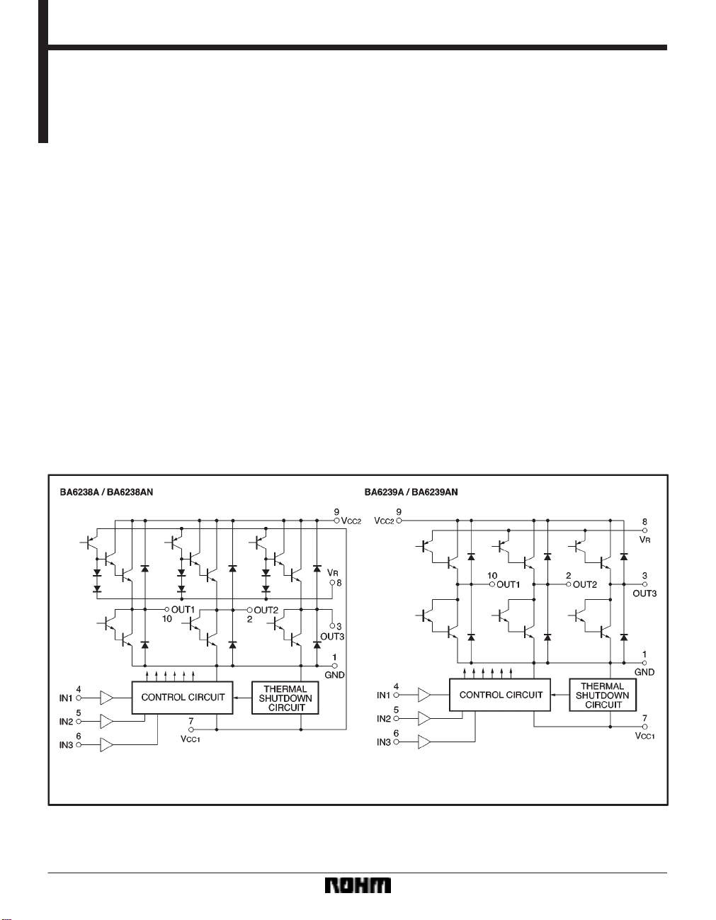
Block diagram
490
Page 2
Motor driver ICs BA6238A / BA6238AN / BA6239A / BA6239AN
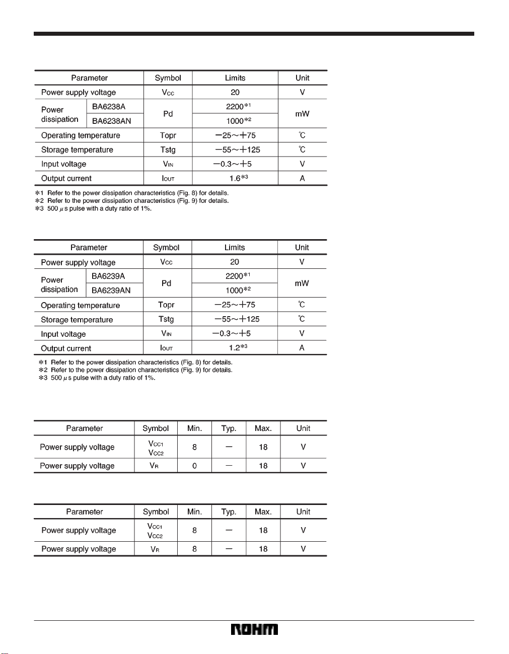
FAbsolute maximum ratings (Ta = 25_C)
BA6238A / BA6238AN
BA6239A / BA6239AN
FRecommended operating conditions (Ta = 25_C)
BA6238A / 6238AN
BA6239A / 6239AN
491
Page 3
Motor driver ICs BA6238A / BA6238AN / BA6239A / BA6239AN
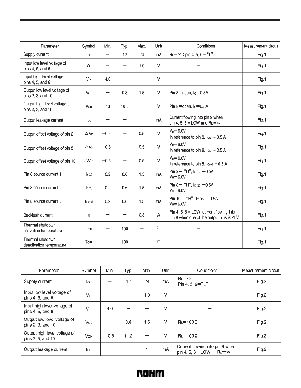
FElectrical characteristics (unless otherwise noted, Ta = 25_C and VCC = 12V)
BA6238A / BA6238AN
BA6239A / BA6239AN
492
Page 4

Motor driver ICs BA6238A / BA6238AN / BA6239A / BA6239AN
Measurement circuits
Application examples
Input / output truth table
493
Page 5

Motor driver ICs BA6238A / BA6238AN / BA6239A / BA6239AN
FCircuit operation
(1) Input (pins 4, 5, and 6)
These pins receive control logic signals. The relevant circuits are designed to have hysteresis and antinoise characteristics. The input circuit can control the logic by input
currents of a few microamperes or more. The motor connected between pins 10 and 2 is selected when pin 4 is
HIGH and pin 5 is LOW, while the motor connected between pins 10 and 3 is selected when pin 5 is HIGH and
pin 4 is LOW. Pin 6 is the forward / reverse control input
pin.
(2) Output (pins 2, 3, and 10)
Pin 10 is the common pin. Either pin 2 or 3 is left OPEN
during motor driving. The waveform monitored on the
OPEN pin will be the same as that on pin 10.
(1) BA6238A / BA6238AN
The output stage configuration of the BA6238A /
BA6238AN is shown in Fig. 5. The output stage contains
NPN transistors in a Darlington configuration, which
means the saturation voltage between V
CC1 and the out-
put pin is rather high but the output voltage can be easily
set by using a zener diode or a resistor voltage divider.
The voltage on the V
R pin can be varied from 0V to VCC1.
The output voltage is at the maximum when pin 8 is
OPEN.
OH=VCC1–Vsat (PNP)–2 VBE (NPN Darlington)
V
OL=Vsat (NPN Darlington)
V
sat and VBE are functions of the output current (see Fig.
V
17).
(2) BA6239A / BA6239AN
The output configuration of the BA6239A / BA6239AN is
shown in Fig. 6. Because the output stage contains only
one NPN transistor, the saturation voltage between pin
8 and the output pin is about 0.7V less than that in the
BA6238A. The output voltage is controlled by the pin-8
voltage. The voltage on the V
CC1. The output voltage is at the maximum when pin
to V
CC1.
8 is V
R pin can be varied from 8V
V
OH=VR–Vsat (PNP)–VBE (NPN)
OL=Vsat (NPN Darlington)
V
sat and VBE are functions of the output current (see Fig.
V
18).
(3) Output control (pin 8)
Output voltage can be varied by controlling the pin-8 voltage.
(1) BA6238A / BA6238AN
The pin-8 voltage can vary from 0V to V
CC. Because a
constant current (0.6mA typically) flows out from pin 8,
the output voltage can be controlled by using a zener
diode or a resistor voltage divider.
(2) BA6239A / BA6239AN
In addition to controlling the output voltage, pin 8 supplies
base current to the high-side output transistor (NPN).
(4) Power supply (pins 7 and 9)
Pin 7 supplies power to the input, logic, and thermal shutdown circuits. Pin 9 supplies power to the output transistors.
(5) Thermal shutdown circuit
Regardless of the input mode, the thermal shutdown circuit puts the outputs to LOW level when the chip temperature rises due to such an event as motor locking. When
the thermal shutdown circuit is deactivated, the outputs
revert to the status determined by input mode.
The thermal shutdown circuit is activated when the chip
temperature exceeds 150_C (125_C minimally), and
deactivated when the chip temperature drops to 100_C
(125_C maximally). The minimum temperature difference between the activation and deactivation settings is
10_C.
(6) Ground pin and fins
Pin 1 and the fins have the minimum potential within the
IC. The PCB design should ensure that the common impedance is kept as low as possible when a large current
flows.
494
Page 6

Motor driver ICs BA6238A / BA6238AN / BA6239A / BA6239AN
Operation notes
(1) Though the IC input pins can be directly connected
with MOS output pins, it is recommendable to connect resistors of about 3 X 30kΩ between the pins for the sake
of pin protection (see Fig. 7).
(2) When reversing the rotational direction of a motor,
make sure to go through the brake mode in-between the
opposite directions. It is recommendable to keep the
brake mode for at least 10µs.
(3) Powering procedures should be designed so that
CC1 (pin 7) always rises first and falls last.
V
(4) The quality of these products have been carefully
checked; however, use of the products with applied voltages, operating temperatures, or other parameters that
exceed the absolute maximum rating given may result in
the damage of the IC and the product it is used in. If the
IC is damaged, the short mode and open modes cannot
be specified, so if the IC is to be used in applications
where parameters may exceed the absolute maximum
ratings, then be sure to incorporate fuses, or other physical safety measures.
(5) Input pins
Voltage should never be applied to the input pins when
the V
CC voltage is not applied to the IC. Similarly, when
CC is applied, the voltage on each input pin should be
V
less than V
CC and within the guaranteed range for the
electrical characteristics.
(6) Back-rush voltage
Depending on the ambient conditions, environment, or
motor characteristics, the back-rush voltage may fluctuate. Be sure to confirm that the back-rush voltage will not
adversely affect the operation of the IC.
(7) Large current line
Large currents are carried by the motor power supply and
motor ground for these ICs.
Therefore, the layout of the pattern of the PC board and
the constants of certain parameters for external components, such as the capacitor between the power supply
and ground, may cause this large output current to flow
back to the input pins, resulting in output oscillation or
other malfunctions. To prevent this, make sure that the
PC board layout and external circuit constants cause no
problems with the characteristics of these ICs.
(8) Power dissipation
The power dissipation will fluctuate depending on the
mounting conditions of the IC and the ambient environment. Make sure to carefully check the thermal design of
the application where these ICs will be used.
(9) Power consumption
The power consumption by the IC varies widely with the
power supply voltage and the output current. Give full
consideration to the power dissipation rating and the
thermal resistance data and transient thermal resistance
data, to provide a thermal design so that none of the ratings for the IC are exceeded.
(10) ASO
Make sure that the output current and supply voltage do
not exceed the ASO values.
(11) Precautions for input mode switching
To ensure reliability, it is recommended that the mode
switching for the motor pass once through the open
mode.
(12) Factors regarding the thermal, power supply, and
motor conditions
If the potential of the output pin sways greatly and goes
below the potential of ground, the operation of the IC may
malfunction or be adversely affected. In such a case,
place a diode between the output and ground, or other
measure, to prevent this.
495
Page 7

Motor driver ICs BA6238A / BA6238AN / BA6239A / BA6239AN
Electrical characteristic curves
496
Page 8

Motor driver ICs BA6238A / BA6238AN / BA6239A / BA6239AN
External dimensions (Units: mm)
497
 Loading...