

Page 1
Optical disc ICs
4-channel BTL driver for CD players
BA6197FP
The BA6197FP , an IC for CD players, has a 4-channel BTL driver , 5V regulator (attached PNP transistor required), standard operational amplifier, and internal reset output linked to an internal thermal shutdown circuit. The driver has gain
adjustment input pins for each channel, allowing gain to be set to the desired value. Also, the internal level shift circuit
helps reduce the number of attached components.
FApplications
CD players, CD-ROM drives and other optical disc devices
FFeatures
1) 4-channel BTL driver on a HSOP 28-pin power package, allowing for application miniaturization.
2) Gain is adjustable with an attached resistor.
3) Internal thermal shutdown circuit with hysteresis capabilities.
4) Internal 5V regulator. (required attached PNP transistor)
5) Internal standard operational amplifier.
6) Reset output pin.
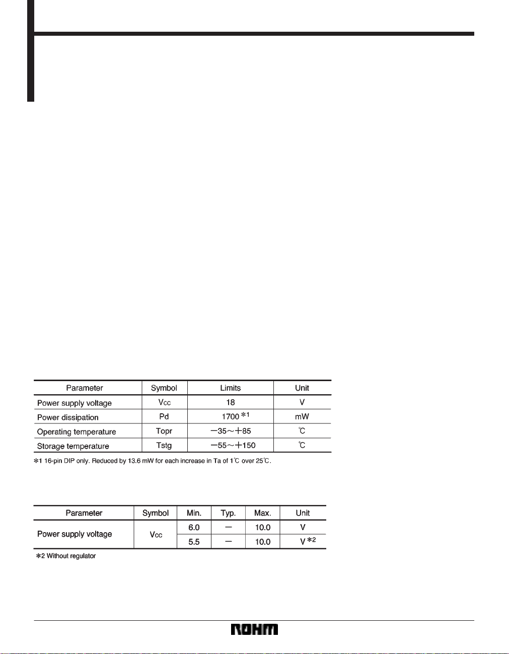
FAbsolute maximum ratings (Ta = 25_C)
FRecommended operating conditions (Ta = 25_C)
298
Page 2
Optical disc ICs BA6197FP
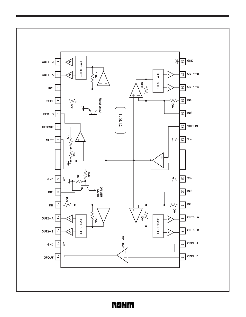
Block diagram
299
Page 3
Optical disc ICs BA6197FP
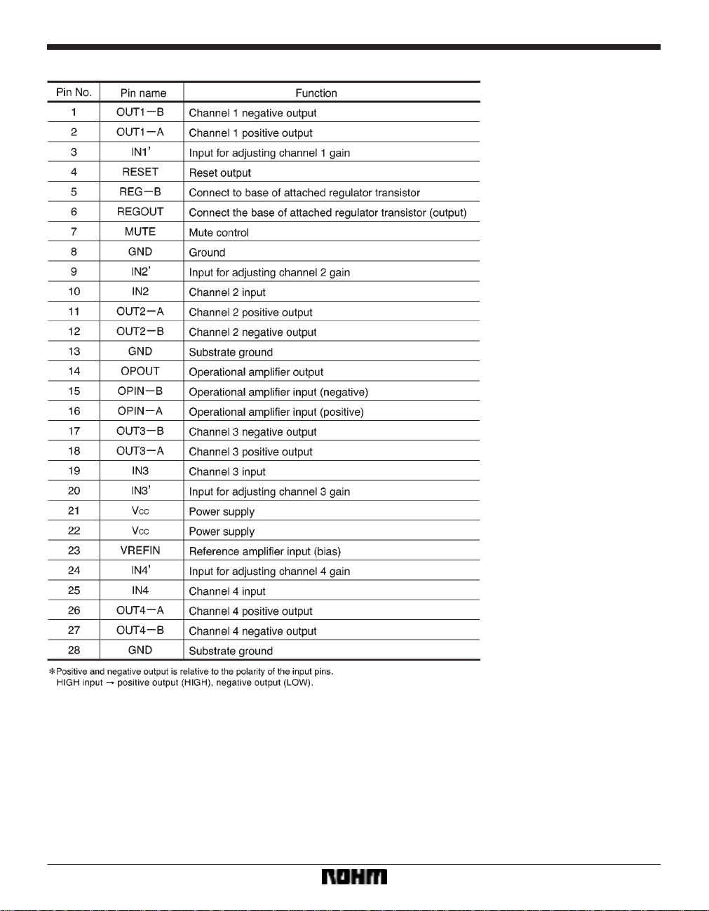
Pin descriptions
300
Page 4

Optical disc ICs BA6197FP
Input / output circuits
301
Page 5

Optical disc ICs BA6197FP
FElectrical characteristics (unless otherwise noted, Ta = 25_C, VCC = 8V, f = 1kHz, RL = 8Ω)
302
Page 6

Optical disc ICs BA6197FP
Measurement circuit
303
Page 7

Optical disc ICs BA6197FP
Measurement circuit switch table
304
Page 8

Optical disc ICs BA6197FP
Application example
305
Page 9

Optical disc ICs BA6197FP
Operation notes
(1) Muting and resetting
(2) The circuit is muted during thermal shutdown and
during the mute-on state. In each case, only the drivers
are muted. During muting, the output pins remain at the
internal bias voltage, roughly (V
(3) When using an attached resistor to change the
gain, the temperature characteristics of the internal feedback resistors results in temperature variation in the gain
(relative to the typical value) of )4600ppm per degree.
There is virtually no temperature variation in error due to
resistance variation.
Electrical characteristic curves
CC-VF)/2.
(4) Be sure to connect the IC to a 0.1µF bypass capacitor to the power supply, at the base of the IC.
(5) The radiating fin is connected to the packages internal GND, but should also be connected to an external
ground.
(6) The capacitor between regulator output (pin 6) and
GND also serves to prevent oscillation of the IC, so select
one with good temperature characteristics.
(7) Pins 5 and 6 may be left open when the regulator
is not used.
(8) Pins 14, 15 and 16 may be left open when the operational amplifier is not used.
306
Page 10

Optical disc ICs BA6197FP
External dimensions (Units: mm)
307
 Loading...