

Page 1
Optical disc ICs
4-channel BTL driver for CD players
BA6196FP
The BA6196FP is an IC designed CD players and has an internal 4-channel BTL driver, 5V regulator (attached PNP
transistor required), standard operational amplifier and a thermal shutdown feature. The driver has gain adjustment input
pins for each channel, allowing gain to be set to the desired value. Also, the internal level shift circuit helps reduce the
number of attached components.
Applications
CD players, CD-ROM drives and other optical disc devices
Features
1) 4-channel BTL driver in a 28-pin HSOP package, for
miniaturization of applications.
2) Gain is adjustable with an attached resistor.
3) Internal thermal shutdown circuit.
4) Internal 5V regulator. (required attached PNP transistor)
5) Internal standard operational amplifier.
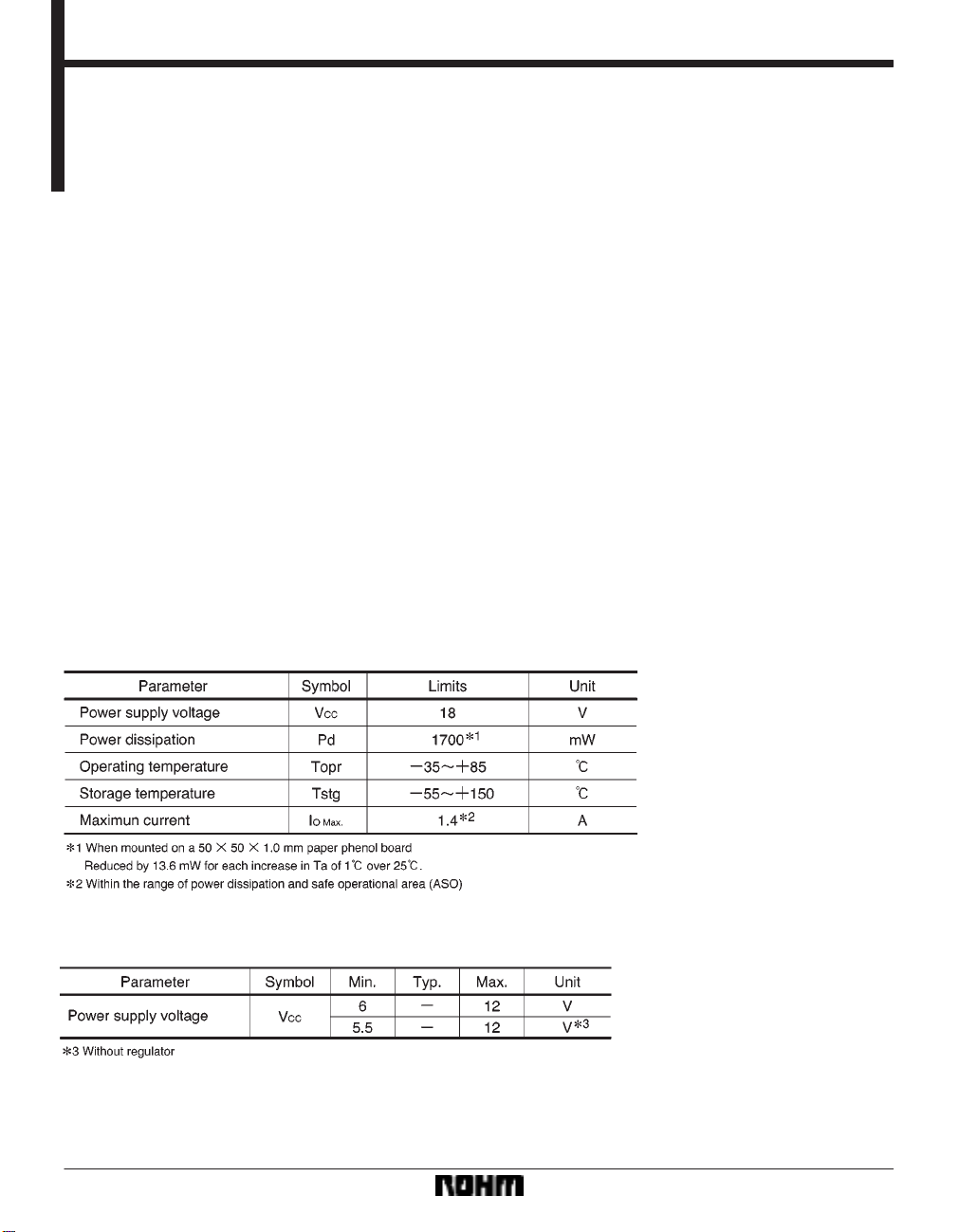
Absolute maximum ratings (Ta = 25C)
Recommended operating conditions (Ta = 25C)
288
Page 2
Optical disc ICs BA6196FP
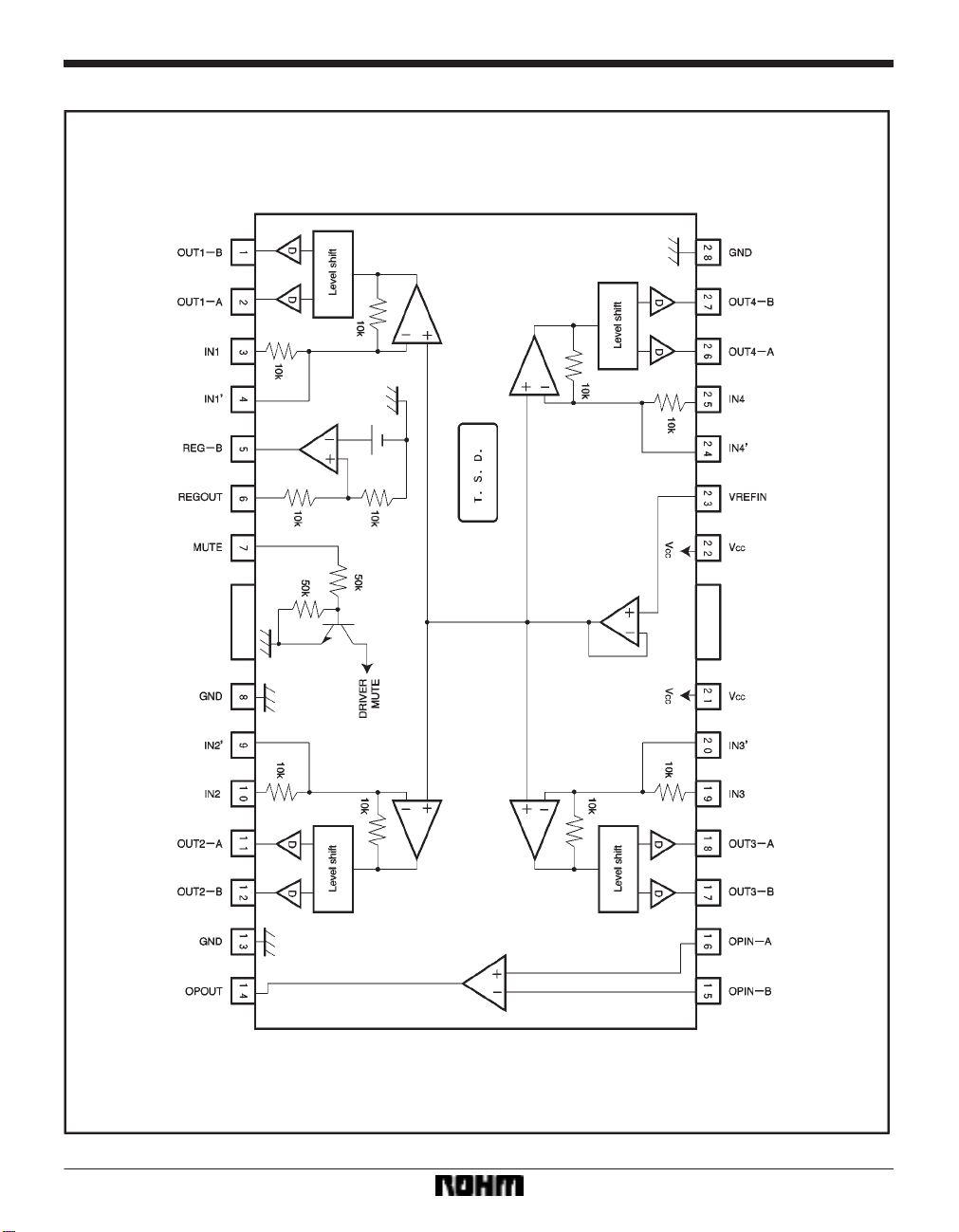
Block diagram
289
Page 3
Optical disc ICs BA6196FP
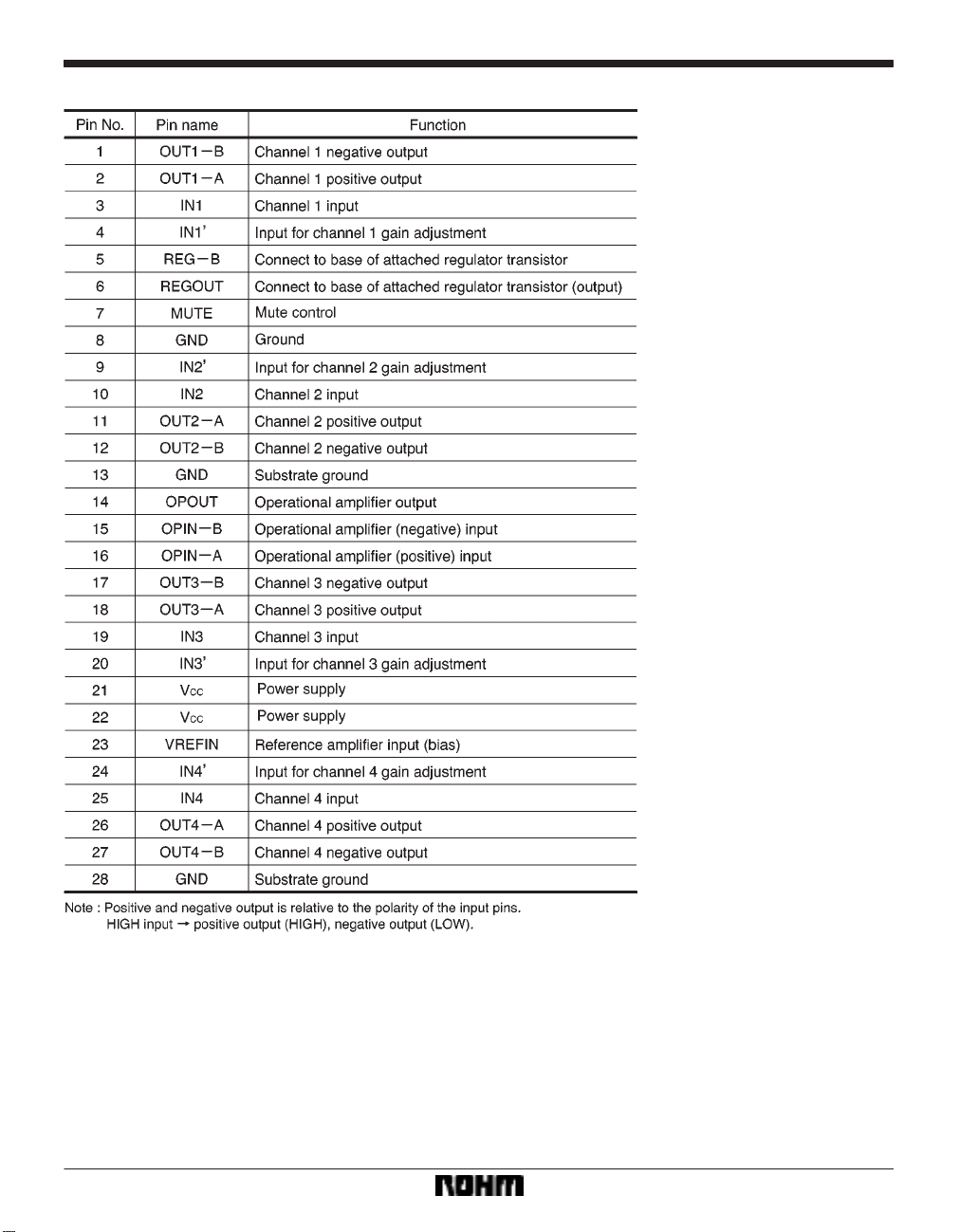
Pin descriptions
290
Page 4

Optical disc ICs BA6196FP
Input / output circuits
291
Page 5

Optical disc ICs BA6196FP
Electrical characteristics (unless otherwise noted, Ta = 25C, VCC = 8V, f = 1kHz, RL = 8Ω)
292
Page 6

Optical disc ICs BA6196FP
Measurement circuit
293
Page 7

Optical disc ICs BA6196FP
Measurement circuit switch table
Operation notes
(1) The BA6196FP has an internal shutdown circuit.
The output current is muted when the chip temperature
exceeds 175C (typically).
(2) If the mute pin (pin 7) voltage is opened or lowered
below 0.5V, the output current will be muted. The mute
pin should be pulled up above 2.0V during normal use.
(3) The bias pin (pin 23) is muted when lowered below
1.4V (typically). Make sure it stays above 1.6V during
normal use.
(4) Muting occurs during thermal shutdown, mute-on
operations or a drop in the bias pin voltage. In each case,
only the drivers are muted. During muting, the output pins
remain at the internal bias voltage, roughly (V
CC–VF)/2.
294
(5) The internal circuits turn off when the supply voltage drops below 4.5V (typically), and turn on again when
it rises above 4.7V (typically).
(6) Be sure to connect the IC to a 0.1µF bypass capacitor to the power supply, at the base of the IC.
(7) The radiating fin is connected to the package’s internal GND, but should also be connected to an external
ground.
(8) The capacitor between regulator output (pin 6) and
GND also serves to prevent oscillation of the IC, so select
one with good temperature characteristics.
Page 8

Optical disc ICs BA6196FP
Application example
295
Page 9

Optical disc ICs BA6196FP
Electrical characteristic curves
296
Page 10

Optical disc ICs BA6196FP
External dimensions (Units: mm)
297
 Loading...