

Page 1
Optical disc ICs
4-channel BTL driver for CD players
and CD-ROMs
BA5970FP
The BA5970FP is a 4-channel BTL driver developed to drive CD player motors and actuators. The driver input stage
contains an operational amplifier, supports a variety of input formats, and allows simple configuration of a filter.
FApplications
CD players, CD-ROM
FFeatures
1) 4-channel BTL driver.
2) Wide dynamic range (4V when PREV
CC = 5V, and RL = 8Ω).
POWV
3) Internal thermal shutdown circuit.
4) Driver gain is adjustable with externally connected
resistor.
CC = 8V,
5) Independent power supplies PREV
channels 1 and 2), and POWV
4), and low voltage operation for a highly efficient
drive.
6) Independent mute pins for channels 1 and 2 and
channels 3 and 4.
7) Perfect for compact applications with the use of the
HSOP28-pin power package.
CC, POWVCC (for
CC (for channels 3 and
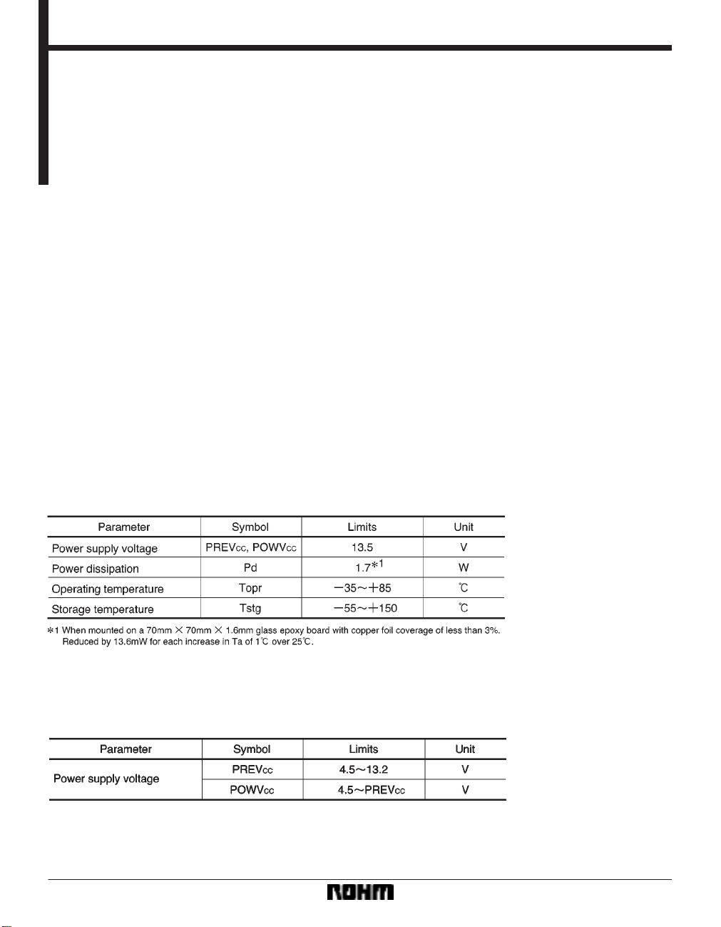
FAbsolute maximum ratings (Ta = 25_C)
FRecommended operating conditions (Ta = 25_C)
653
Page 2
Optical disc ICs BA5970FP
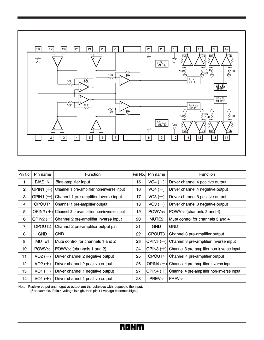
Block diagram
Pin descriptions
654
Page 3
Optical disc ICs BA5970FP
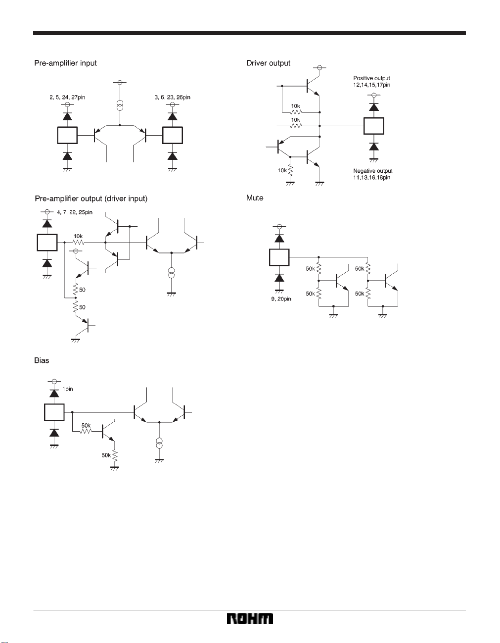
Input / output circuits
655
Page 4

Optical disc ICs BA5970FP
FElectrical characteristics (unless otherwise noted, Ta = 25_C, PREVCC = 8V, POWVCC1 = 5V,
FPOWV
CC2 = 8V, BIAS = 2.5V, RL = 8Ω)
656
Page 5

Optical disc ICs BA5970FP
Measurement circuit
657
Page 6

Optical disc ICs BA5970FP
Measurement circuit switch table
(1) Driver block (OPB ! 1, NF ! 1, OPRL ! 1)
(2) Pre-stage operational amplifier block (VN1 = VM2 = 0V, RL ! OFF)
658
Page 7

Optical disc ICs BA5970FP
Application example
659
Page 8

Optical disc ICs BA5970FP
FOperation notes
(1) The BA5970FP contains a thermal shutdown circuit. When the chip temperature reaches 175_C (Typ.),
the output current is muted. If the chip temperature then
drops below 150_C (Typ.), then the mute is released.
(2) By having the mute pin voltage pulled up to 2.0V or
greater, you can mute the output current. For normal
conditions, have mute pin open or at 0.5V or below. (Pin
9 mutes channels 1 and 2, and pin 20 mutes channels 3
and 4.)
(3) If the voltage of the bias pin (pin 1) drops below 1.4V
(Typ.), outputs are muted. For normal conditions, have
the voltage above 1.7V.
(4) If the power supply voltage drops below 3.8V (Typ.),
FElectrical characteristic curves
internal circuits turns off. If the power supply voltage then
rises to 4.0V (Typ.), the circuits turn on.
(5) If the voltage of the thermal shutdown, mute ON, or
bias pin drops, or if the power supply voltage drops, the
mute is activated; however, in these situations, only the
drivers are muted. Also, the output pin voltage becomes
the internal bias voltage (approx. V
and 2, and (V
CC–VF)/2 for channels 3 and 4).
CC/ 2 for channels 1
(6) Connect a bypass capacitor (approx. 0.1µF) between the bases of the power supply pins of this IC.
(7) Even though the radiation fins are connected to
ground within the package, be sure to also connect them
to a ground externally as well.
660
Page 9

Optical disc ICs BA5970FP
External dimensions (Units: mm)
661
 Loading...