

Page 1
Optical disc ICs
4-channel BTL driver for CD players
BA5937AFP
The BA5937AFP is a 4-channel BTL driver developed for use with CD players. In addition to internal drivers for the focus
coil, tracking coil, and sled motor, it also contains a driver for the loading motor.
FApplications
CD-ROM, CD players
FFeatures
1) Perfect for compact applications with the use of the
HSOP 28-pin power package.
2) Internal thermal shutdown circuit.
3) Gain is adjustable with externally connected resistor.
(For channels 1, 3, and 4.)
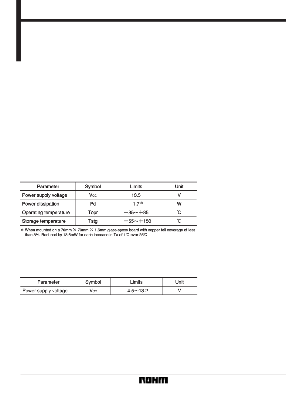
FAbsolute maximum ratings (Ta = 25_C)
4) External mute pin enables the muting of the output
current for channels 1 and 4.
5) Power supply is divided into three systems
(V
CC1 = ch1 and ch4, VCC2 = ch2 and current source,
CC3 = ch3).
V
FRecommended operating conditions (Ta = 25_C)
632
Page 2
Optical disc ICs BA5937AFP
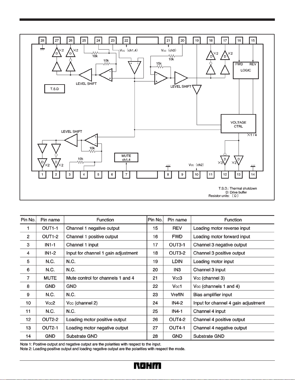
Block diagram
Pin descriptions
633
Page 3
Optical disc ICs BA5937AFP
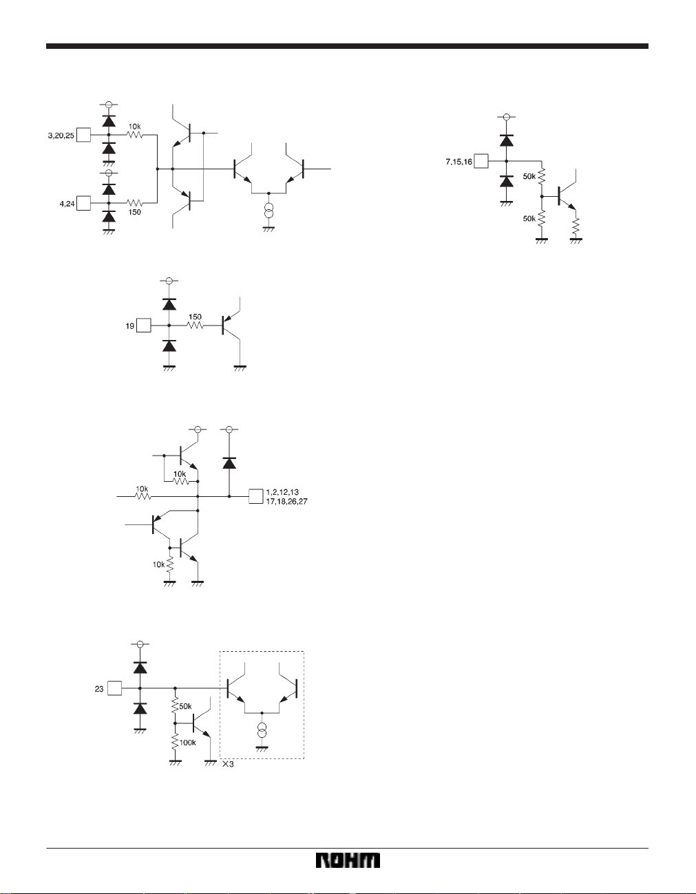
Input / output circuits
634
Page 4

Optical disc ICs BA5937AFP
FElectrical characteristics (unless otherwise noted, Ta = 25_C, VCC = 8V, RL = 8Ω, VBIAS = 2.5V)
635
Page 5

Optical disc ICs BA5937AFP
Measurement circuit
636
Page 6

Optical disc ICs BA5937AFP
Application example
637
Page 7

Optical disc ICs BA5937AFP
Operation notes
(1) Output mode switch for loading motor driver (V
CC = 8V)
Note: Loading driver gain is 0dB.
638
Page 8

Optical disc ICs BA5937AFP
(2) Voltage setting for loading motor driver (ex: forward mode)
∗When setting the output voltage from the loading driver,
even if an output voltage is set that exceeds the maximum output voltage with respect to the power supply
voltage, the output will not exceed the maximum output
voltage.
If a voltage is set that is under the maximum output voltage, the example above is applicable. Also, by having the
loading input (pin 19) open, the maximum output voltage
with respect to the power supply voltage is output.
(3) The BA5937AFP contains a thermal shutdown circuit.
When the chip temperature reaches 175C (Typ.), the
output current is muted. If the chip temperature then
drops below 150C (Typ.), then the mute is released.
(4) If the voltage of the bias pin (pin 23) drops below
1.0V (Typ.), outputs are muted.
For normal conditions, have the voltage above 1.4V and
below 6.5V.
(5) By having the mute pin (pin 7) voltage pulled up to
2.0V or greater, you can mute the output current for channels 1 and 4. For normal conditions, have pin 7 open or
at 0.5V or below.
(6) If the voltage of the thermal shutdown, mute ON, or
bias pin drops, the mute is activated; however, in these
situations, only the drivers are muted. Also, the output pin
voltage becomes the internal bias voltage (approx.
(V
CC*VF)/2).
(7) Connect a bypass capacitor (approx. 0.1µF) between the bases of the power supply pins of this IC.
(8) Even though the radiation fins are connected to
ground within the package, be sure to also connect them
to a ground externally as well.
639
Page 9

Optical disc ICs BA5937AFP
Electrical characteristic curves
External dimensions (Units: mm)
640
 Loading...