

Page 1
Optical disc ICs
4-channel BTL driver for CD players
BA5934FP
The BA5934FP is a 4-channel BTL driver developed to drive CD player motors and actuators. Perfect for compact applications with the use of the HSOP 28-pin power package.
Applications
CD players, CD-ROM
Features
1) In addition to internal drivers for the focus coil, tracking coil, and sled motor, it also contains a driver for
the loading motor.
2) Perfect for compact applications with the use of the
HSOP 28-pin power package.
3) Requires few external components.
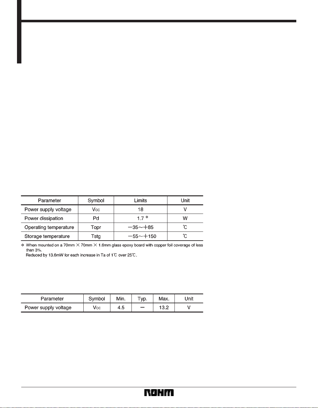
Absolute maximum ratings (Ta = 25C)
4) Driver gain is adjustable with a single externally connected resistor.
5) Internal thermal shutdown circuit.
6) External mute pin enables the muting of the output
current for channel 4.
Recommended operating conditions (Ta = 25C)
718
Page 2
Optical disc ICs BA5934FP
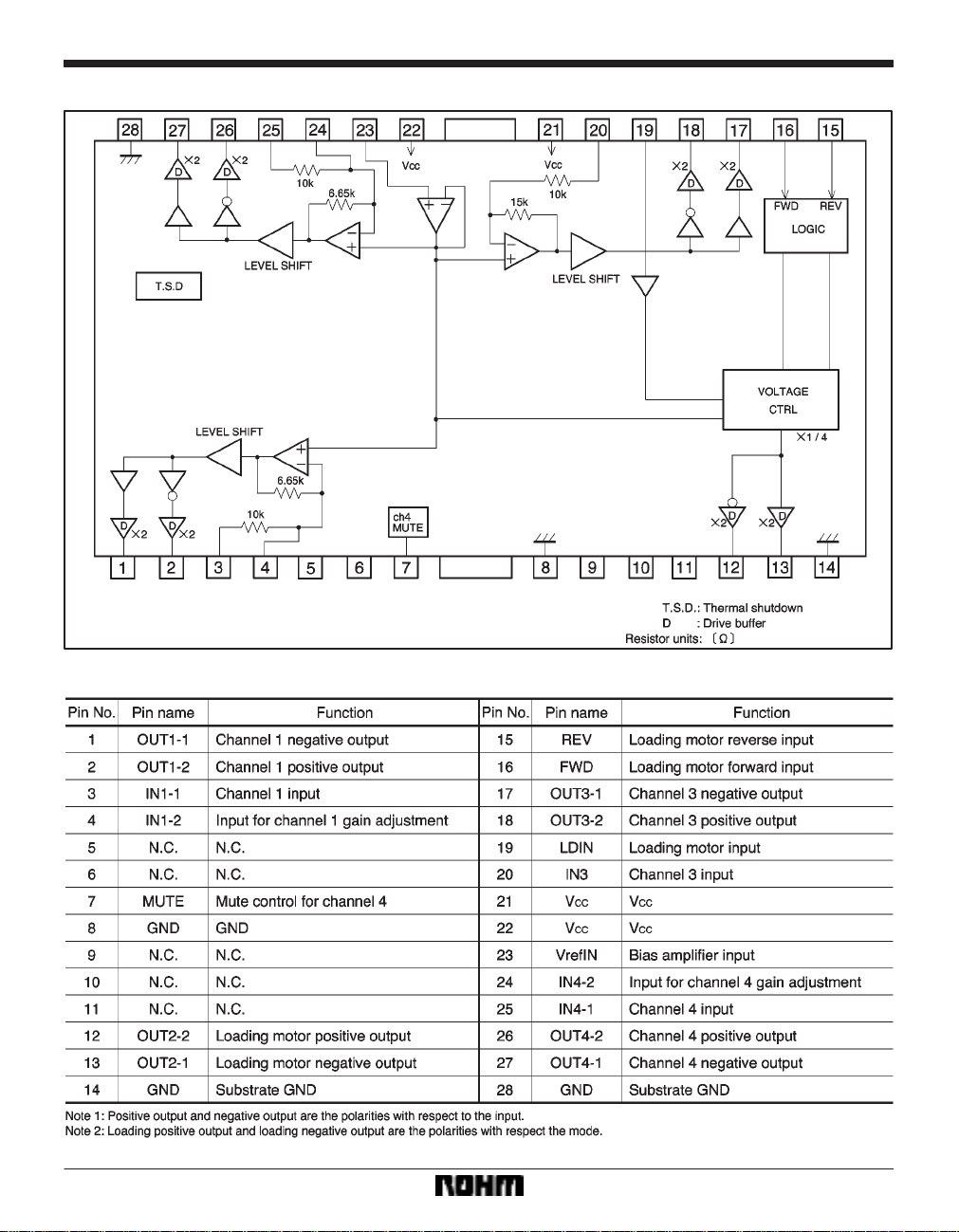
Block diagram
Pin descriptions
719
Page 3
Optical disc ICs BA5934FP
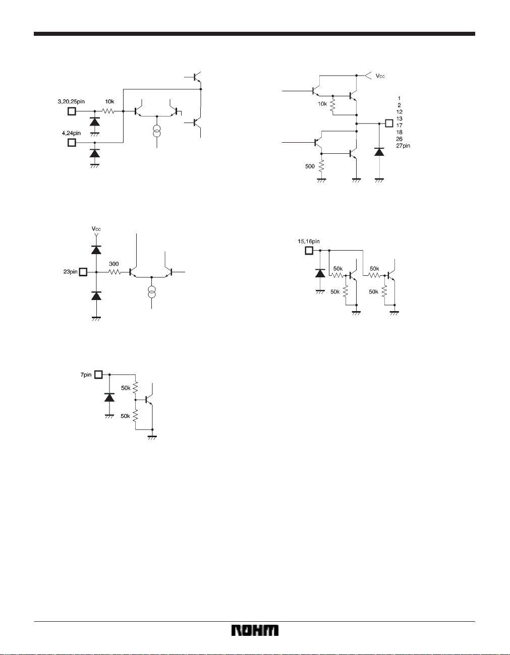
Input / output circuits
720
Page 4

Optical disc ICs BA5934FP
Electrical characteristics (unless otherwise noted, Ta = 25C, VCC = 8V, RL = 8Ω, VBIAS = 2.5V)
721
Page 5

Optical disc ICs BA5934FP
Measurement circuit
722
Page 6

Optical disc ICs BA5934FP
Circuit operation
(1) Driver block
The input is the focus and tracking error signals from the
servo pre-amplifier and the control signals for the motor
system.
The input signal is normally centered at 2.5V , and at the
pre-amplifier, it undergoes V/ I conversion to generate
the current corresponding to the input voltage. This is
then passed through a resistor and sent to the internal
reference voltage block.
This results in the output from the pre-amplifier being the
signal at the center of the internal reference voltage.
Furthermore, at the V/I conversion, forward and reverse
phases are generated and the BTL output is then gained
through the driver buffer.
723
Page 7

Optical disc ICs BA5934FP
(2) Output mode switch for loading motor driver (VCC = 8V)
Note: Loading driver gain is 0dB.
(3) Voltage setting for loading motor driver (ex: forward mode)
∗ When setting the output voltage from the loading driver, even if an output voltage is set that exceeds the maximum
output voltage with respect to the power supply voltage, the output will not exceed the maximum output voltage.
If a voltage is set that is under the maximum output voltage, the example above is applicable. Also, by having the loading
input (pin 19) open, the maximum output voltage with respect to the power supply voltage is output.
724
Page 8

Optical disc ICs BA5934FP
Application example
725
Page 9

Optical disc ICs BA5934FP
Operation notes
(1) The BA5934FP contains a thermal shutdown circuit. When the chip temperature reaches 175C (Typ.),
the output current is muted.
(2) By having the mute pin (pin 7) voltage pulled up to
2.0V or greater, you can mute the output current for chan-
nels 1 and 4. For normal conditions, have pin 7 open or
at 0.5V or below.
The figure below is the timing chart for the high-impedance mute.
(3) If the voltage of the bias pin (pin 23) drops below
1.4V (Typ.), outputs are muted. For normal conditions,
have the voltage above 1.6V and below 6.5V.
(4) If the voltage of the thermal shutdown or bias pin
drops, the mute is activated; however, in these situations,
only the drivers are muted. Also, the output pin voltage
becomes the internal bias voltage (approx. (V
Electrical characteristic curves
CCVF)/2).
(5) Connect a bypass capacitor (approx. 0.1µF) between the bases of the power supply pins of this IC.
(6) Even though the radiation fins are connected to
ground within the package, be sure to also connect them
to a ground externally as well.
726
Page 10

Optical disc ICs BA5934FP
External dimensions (Units: mm)
727
 Loading...