

Page 1
278
Optical disc ICs
4-channel BTL driver for CD players
BA5931FP
The BA5931FP is a 4-channel BTL driver designed for CD player motors and actuators. The 28-pin HSOP package allows for application miniaturization.
FApplications
CD players, CD-ROM drives
FFeatures
1) Internal drivers for focus coils, tracking coils, spindle
motors, feed motors and loading.
2) HSOP 28-pin package allows for miniaturization of
applications.
3) Low number of external components.
4) Driver gain is adjustable with a single attached resistor.
5) Internal thermal shutdown circuit.
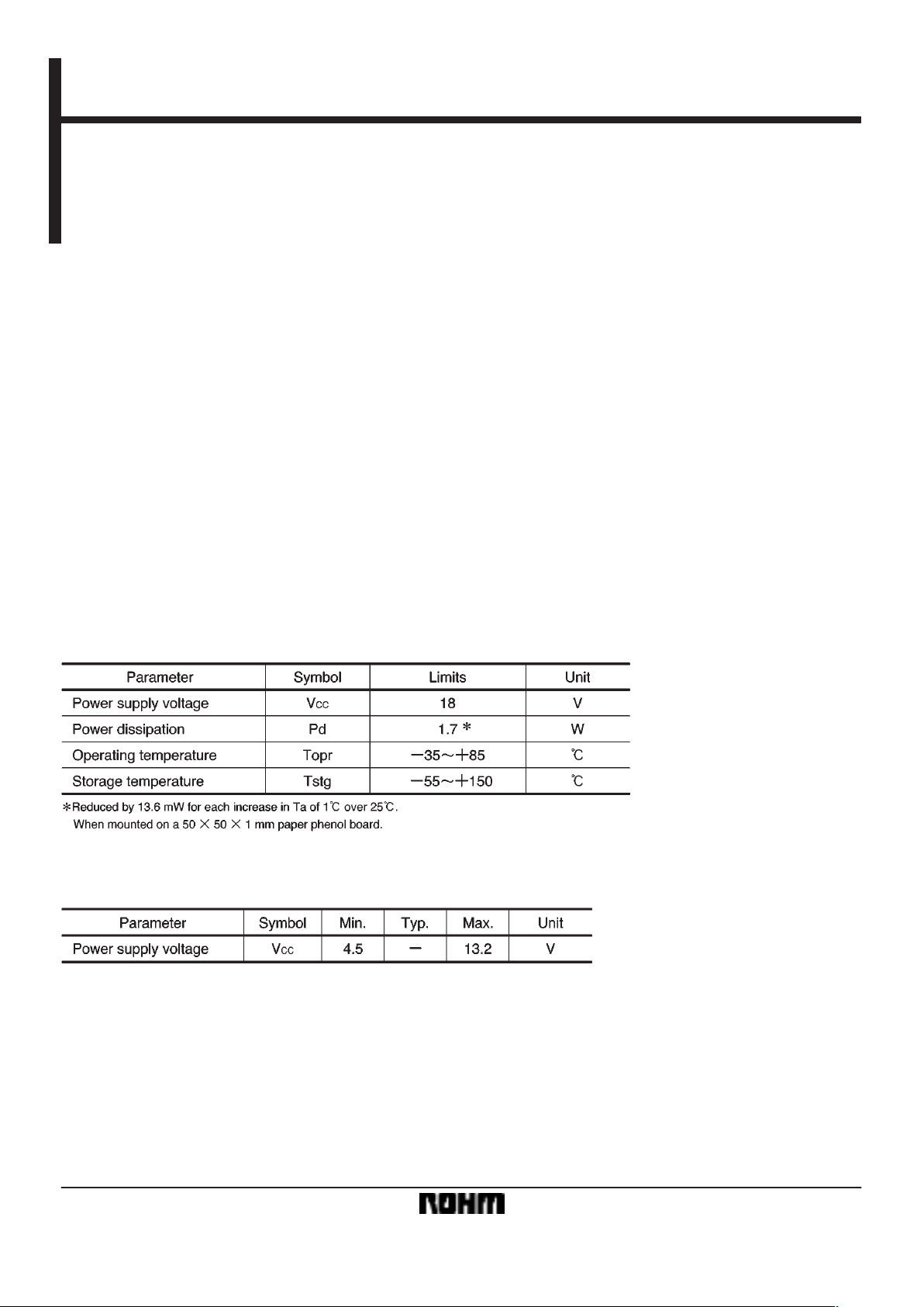
FAbsolute maximum ratings (Ta = 25_C)
FRecommended operating conditions (Ta = 25_C)
Page 2
279
Optical disc ICs BA5931FP
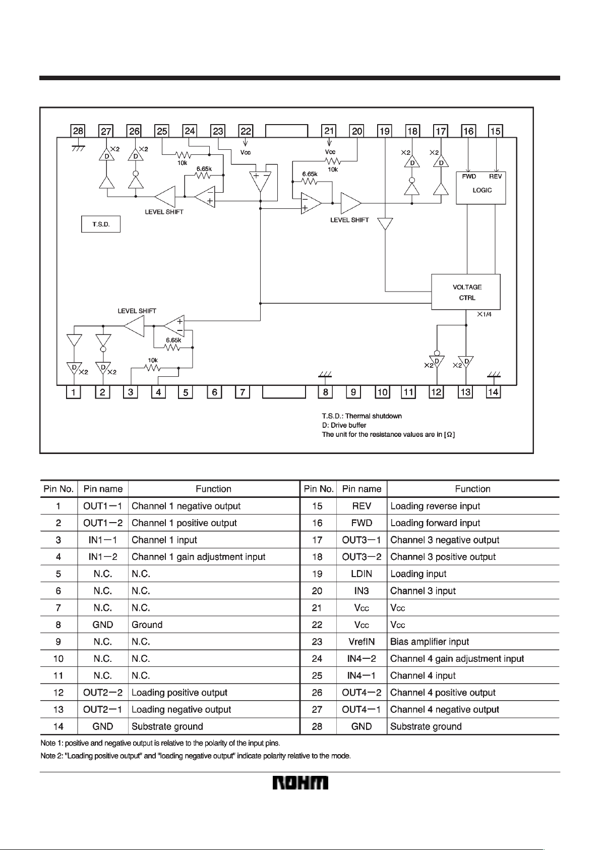
Block diagram
Pin descriptions
Page 3

280
Optical disc ICs BA5931FP
Input/output circuits
Page 4

281
Optical disc ICs BA5931FP
FElectrical characteristics (unless otherwise noted, Ta = 25_C, VCC = 8V, RL = 8Ω, Vb = 2.5V)
Page 5

282
Optical disc ICs BA5931FP
Measurement circuit
Page 6

283
Optical disc ICs BA5931FP
Circuit operation
(1) Driver
Inputs to the IC are the focus tracking error signal from
the servo preamplifier and the control signal from the motor. The input signals, which normally center on 2.5V , are
V /I converted by the preamplifier, generating a current
corresponding to the input voltage. This current is
passed through a resistor and into the internal reference
voltage component, the preamplifier output being a signal centering on the internal reference voltage. Two systems (positive phase and negative phase) are created
during V/I conversion, generating BTL output via the
driver buffer.
Page 7

284
Optical disc ICs BA5931FP
(2) Switching the loading motor driver output mode (VCC = 8V)
Note: Loading driver gain = 0dB
(3) Setting the loading driver voltage (forward mode)
Note: The loading output voltage will not exceed the power supply’s maximum output voltage, even if set above this maximum voltage.
The example above applies only when setting below the maximum output voltage. Maximum output voltage for the power supply can be output by opening
the loading input pin (19 pin).
Page 8

285
Optical disc ICs BA5931FP
Application example
Page 9

286
Optical disc ICs BA5931FP
FOperation notes
(1) The BA5931FP has a thermal shutdown circuit.
The output current is muted when the chip temperature
rises above 175_C (typically).
(2) The IC is muted when the bias pin (pin 23) is lowered below 1.4V (typically). Make sure it stays between
1.6V and 6.5V during normal use.
(3) Muting occurs during thermal shutdown or a drop in
the bias pin voltage. In each case, only the drivers are
muted. During muting, the output pins remain at the internal bias voltage, (approx V
CC/2).
(4) Connect the IC to a 0.1µF bypass capacitor between power supplies, at the base of the IC.
(5) The radiating fin is connected to the package’s internal GND, but should also be connected to an external
ground.
FElectrical characteristic curves
Page 10

External dimensions (Units: mm)
287
Optical disc ICs BA5931FP
 Loading...