

Page 1
Optical disc ICs
2-channel BTL driver for CD players
BA5912AFP-Y
The BA5912AFP-Y is a 2-channel BTL driver developed to drive CD player motors and actuators. Perfect for compact
applications with the use of the HSOP 25-pin package.
FApplications
CD players, CD-ROM
FFeatures
1) 2-channel BTL driver.
2) Perfect for compact applications with the use of the
HSOP 25-pin power package.
3) Wide dynamic range.
4) External mute pin enables the muting of the output
current (independent muting for channels 1 and 2).
Muting both channels causes the IC to enter the
standby mode.
5) Two internal multi-purpose operational amplifiers.
6) Power supply is divided into three systems (Pre V
Pow V
CC for channel 1, and Pow VCC for channel 2)
7) Internal standard two operational amplifier.
8) Internal thermal shutdown circuit.
CC,
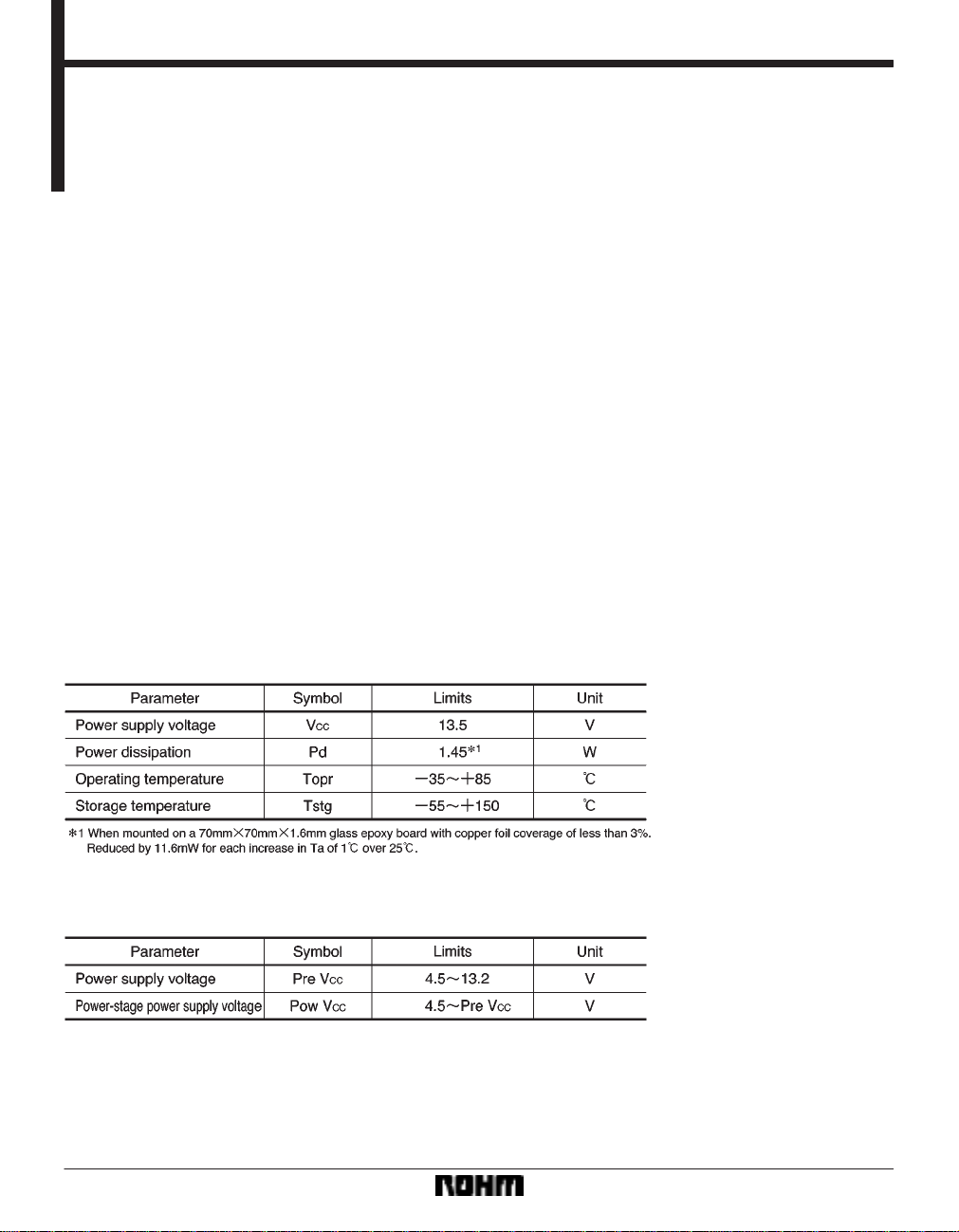
FAbsolute maximum ratings (Ta = 25 _C)
FRecommended operating conditions (Ta = 25 _C)
589
Page 2
Optical disc ICs BA5912AFP-Y
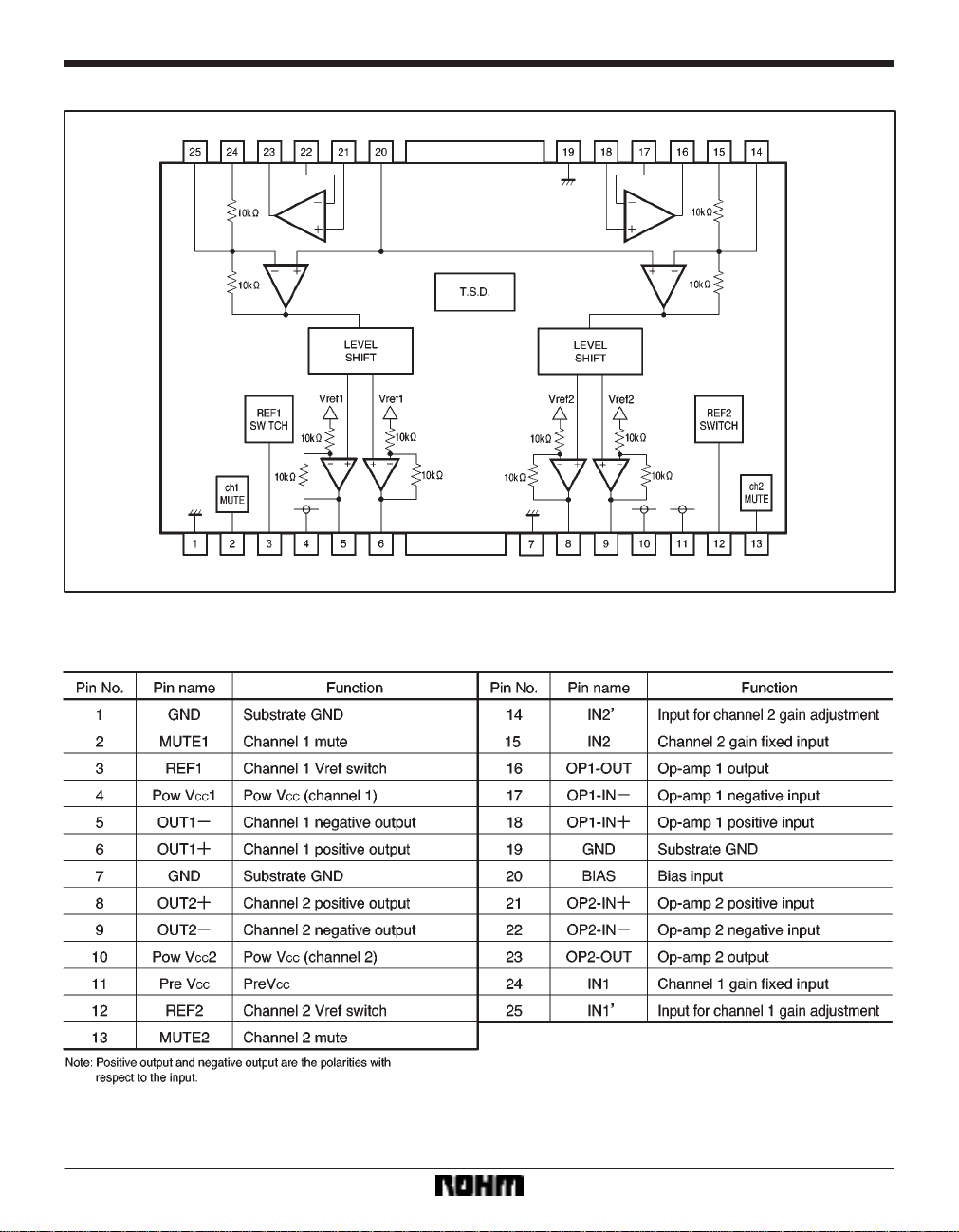
Block diagram
Pin descriptions
590
Page 3
Optical disc ICs BA5912AFP-Y
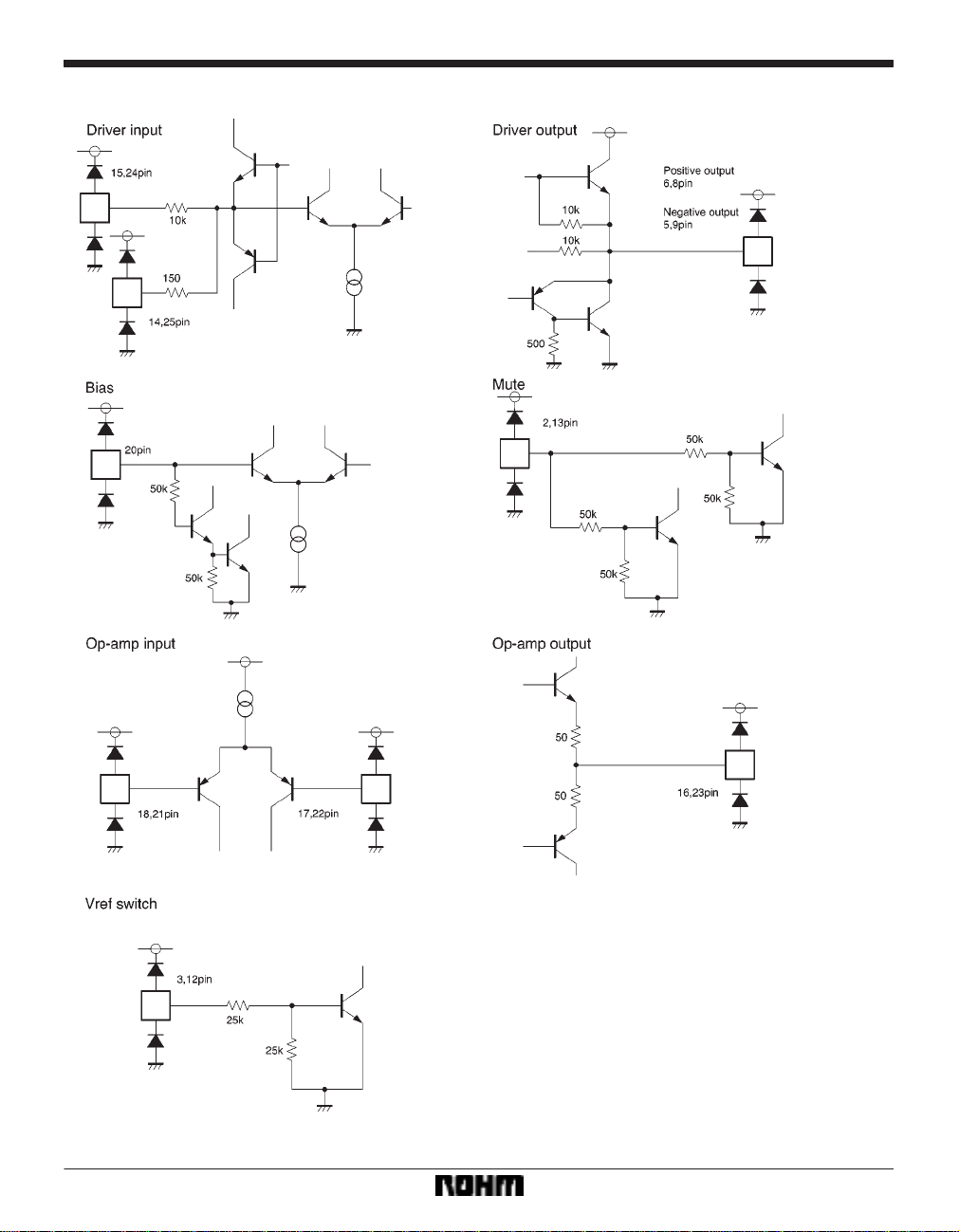
Input / output circuits
591
Page 4

Optical disc ICs BA5912AFP-Y
FElectrical characteristics (unless otherwise noted, Ta = 25 _C, Pre VCC = Pow VCC = 5V, BIAS = 2.5V, RL = 8Ω)
592
Page 5

Optical disc ICs BA5912AFP-Y
Measurement circuits
〈Driver block〉
593
Page 6

Optical disc ICs BA5912AFP-Y
〈Operational amplifier block〉
Application example
594
Page 7

Optical disc ICs BA5912AFP-Y
FOperation notes
(1) The BA5912AFP-Y contains a thermal shutdown
circuit. When the chip temperature reaches 175 _C
(Typ.), the output current is muted. If the chip temperature then drops below 150_C (Typ.), then the mute is released.
(2) By having the voltage of the mute pins (pins 2 and
13) open or lowered to 0.5V or below, you can independently mute the output current for channels 1 and 2. For
normal conditions, have the voltages for the mute pins
(pins 2 and 13) pulled up to 2.0V or greater. If the both
mute pins (pins 2 and 13) are open or 0.5V or less, then
the IC automatically enters the standby mode.
(3) If the voltage of the bias pin (pin 20) drops below
1.4V (Typ.), outputs are muted. For normal conditions,
have the voltage above 2.0V.
(4) If the power supply voltage drops below 3.5V (Typ.),
internal circuits turn off. If the power supply voltage then
rises to 4.0V (Typ.), the circuits turn on.
FElectrical characteristic curves
(5) If the voltage of the thermal shutdown, mute ON, or
bias pin drops, or if the power supply voltage drops, the
mute is activated; however, in these situations, only the
drivers are muted. Also, the output pin voltage becomes
the internal bias voltage.
(6) When Pre V
CC = Pow VCC, have the Vref switch pin
open or at 0.5V or less (internal bias voltage = (Pow
V
CC*VF) / 2). When Pre VCC > POW VCC)VF, have the
Vref switch pin pulled up to 2.0V (internal bias voltage =
CC / 2).
Pow V
(7) Connect a bypass capacitor (approx. 0.1µF) between the bases of the power supply pins of this IC.
(8) Even though the radiation fins are connected to
ground within the package, be sure to also connect them
to a ground externally as well.
595
Page 8

Optical disc ICs BA5912AFP-Y
External dimensions (Units: mm)
596
 Loading...