

Page 1

Audio ICs
ALS headphone driver
BA3570F / BA3570FS
The BA3570F and BA3570FS are stereo headphone amplifiers with ALS (Auto Loudness System) which have been
designed for use as headphone drivers in audio equipment.
Applications
Stereo headphones
Features
1) The use of ALS (Auto Loudness System) makes it
possible to obtain a dynamic sound regardless of the
volume level.
Block diagram
2) Built-in power mute circuit.
3) Built-in bypass circuit.
554
Page 2

Audio ICs BA3570F / BA3570FS
FPin descriptions (pin numbers are for 22-pin BA3570F)
FAbsolute maximum ratings (Ta = 25_C)
FRecommended operating conditions (Ta = 25_C)
555
Page 3
Audio ICs BA3570F / BA3570FS
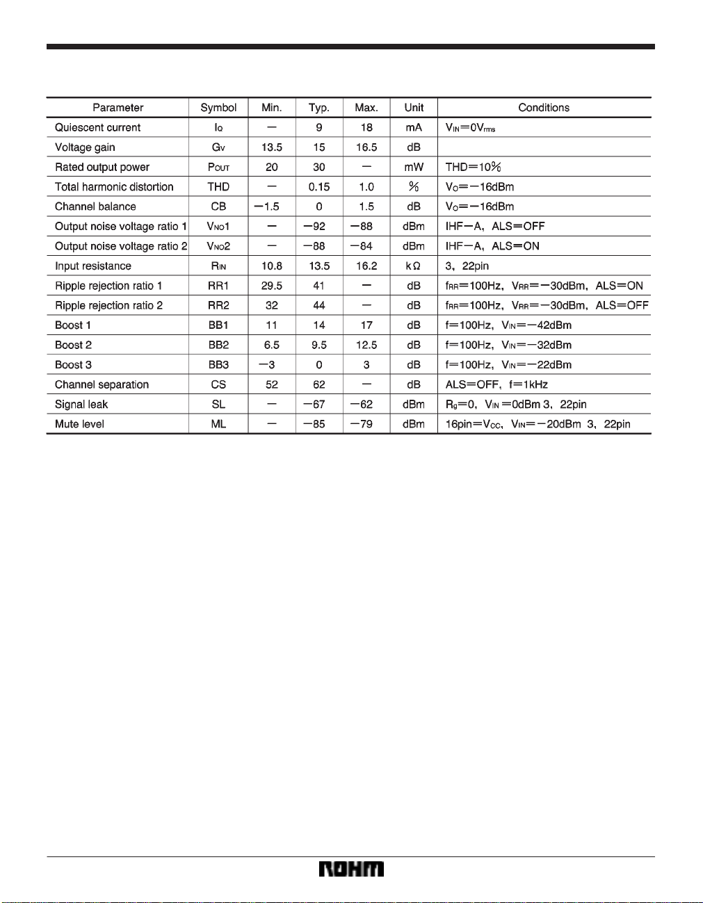
FElectrical characteristics (unless otherwise noted, Ta = 25_C, VCC = 3.0V, RL = 16Ω, f = 1kHz,
and the measurement circuit is as shown in Fig. 1)
556
Page 4

Audio ICs BA3570F / BA3570FS
Measurement circuit
Explanation of ALS operation and attached components (pin numbers are for 22-pin BA3570F)
(1) ALS ON
When ALS is on, the signal circuit (including external connections) is as shown in Fig. 2.
557
Page 5

Audio ICs BA3570F / BA3570FS
1) Bass signal transmission and gain vs. frequency
2) Treble signal transmission and gain vs.
frequency
The gain and cutoff frequency of each block is as follows:
LPF1 cutoff frequency : (Hz)
Amp A gain : G
ATT attenuation : (dB)
CL1=
f
V(A) = 0 (dB)
GV(ATT) = 20log
1
2π S (R3//R4) S C4
EVR
R10EVR
Amp B gain : (dB)
Amp B cutoff
frequency
LPF2 cutoff frequency : (Hz)
Amp C gain : G
Amp D gain : (dB)
Mute switch gain : G
GV(B) = 20log
:
fCL3 =
fCL2 =
V(C) = 0 (dB)
GV(D) = 20log
V(MUTE) = 0 (dB)
R7R11
1
2π S R7 S C11
1
2π S R12 S C12
R14
R13
R7
(Hz)
558
R15+R16
Amp E gain :
GV(E) = 20log
R15
(dB) 15dB
In this case, R3 = R4 = 2SR12 (= 100kΩ) and C4 = C12 (=
0.1µF), therefore f
CL1 = fCL2 (= 32Hz), and the frequency
characteristic is bass boost (12 dB/OCT) as shown in
Fig. 4. Also, R
EVR MAX total gain G
14 = 2SR13, therefore GV(D) = 6 (dB) and the
LMAX when signals are input from
both channels is
GLMAX = G
V(A)+GV(B)+GV(C)+GV(D)
GLMAX = +GV(MUTE)+GV(E)
GLMAX = GV(B)+6+15 (dB)
The gain and cutoff frequency of each block is as follows:
HPF cutoff
frequency 1
:
fCH1 =
1
2π S (R6+R8) S C10
(Hz)
Page 6

Audio ICs BA3570F / BA3570FS
HPF cutoff
frequency 2
Amp D gain :
:
fCH2 =
GV(D) = 20log
Furthermore, as R
V(D) = +9.5 (dB)
G
The total gain G
GH1 = 20log
H1 for the frequency band ftfCH1 is
9
R
8+R9
R
and the total gain G
GH2 = 20log
6 //R8+R9
R
2π S (R6R8+R8R10+R6R10) S C10
14 = 2R13,
H2 for the frequency band fCH2tf is
R
9
R8+R9
(Hz)
R13
R13+R14
(dB)
+9.5+15 (dB)
+9.5+15 (dB)
3) Combined frequency characteristics
As shown in Fig. 6, the ALS characteristics can be obtained from the bass characteristics (Fig. 4) and the
treble characteristics (Fig. 6).
Amp D’ gain:
As R
17 = R18 and R19 = R20, the total gain GV(OFF) when ALS
GV(D) = 20log
R19+R20
19
R
is off is
G
V (OFF) = GV (ATT2) +GV (D) +GV (MUTE) +GV (E) = 15 (dB)
*6 )60
15
and it is flat as shown in Fig. 8.
(dB)
(2) ALS OFF
The signal circuit when ALS is off is shown in Fig. 7.
The gain and cutoff frequency of each block is as follows:
ATT2 attenuation:
GV(ATT2) = 20log
17+R18
R
R18
(dB)
559
Page 7

Audio ICs BA3570F / BA3570FS
FExplanation of ALS operation and attached components
(1) ALS system control circuit
The ALS system control circuit is shown in Fig. 9.
S ALS mode switching table
FMute amplifier (pin numbers are for 22-pin BA3570F)
The output muting can be switched on or off.
FMute switching table
S ALS SW τ external connection value: C13
By increasing the capacitance of C13, the switching
sound made when ALS is turned on or off can be reduced, however, the switching time will increase. Set the
value appropriately for the application.
S ALSτ external connection value: C14
The ALC attack and recovery time for ALS is determined
by C14 connected to the τ pin (Pin 9).
560
FMUTE SWτ external connection value: C8
By increasing the capacitance of C8, the switching
sound made when the mute is turned on or off can be
reduced, however, the switching time will increase. Set
the value appropriately for the application.
Page 8

Audio ICs BA3570F / BA3570FS
Application example
Electrical characteristic curves
561
Page 9

Audio ICs BA3570F / BA3570FS
562
Page 10

Audio ICs BA3570F / BA3570FS
External dimensions (Units: mm)
563
 Loading...