

Page 1
Audio ICs
Mute detector IC
BA336 / BA338 / BA338L
The BA336, BA338 and BA338L are monolithic ICs designed for mute detection and tape end detection. When a duration
of silence (52dBm or less) exceeds the time constant set with an external CR circuit, a song gap is identified, and after
this a plunger control signal is output during a pulse whose width is determined by another external CR circuit. These
functions are contained in a compact 9-pin package.
The circuit configuration consists of a pre-amp with limiter, a comparator flip-flop, and a driver . Circuitry is also included
which prevents errors when the power is turned on, and measures have been taken to prevent errors due to excessive
input, song gap noise, and other factors.
Applications
Mute detection
Tape end detection
Features
1) Mute detection time and output pulse width can be
set within a broad range by an external CR circuit.
2) Includes circuit for preventing errors due to song gap
noise.
3) Includes over-current protection circuit.
4) Includes circuit for preventing errors when the power
is turned on.
5) Detection can be stopped using an external input.
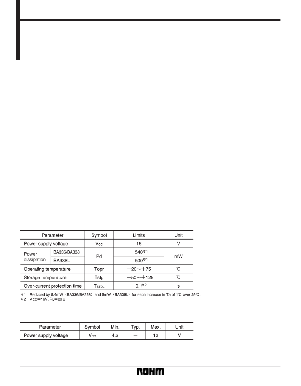
Absolute maximum ratings (Ta = 25C)
Recommended operating conditions (Ta = 25C)
726
Page 2
Audio ICs BA336 / BA338 / BA338L
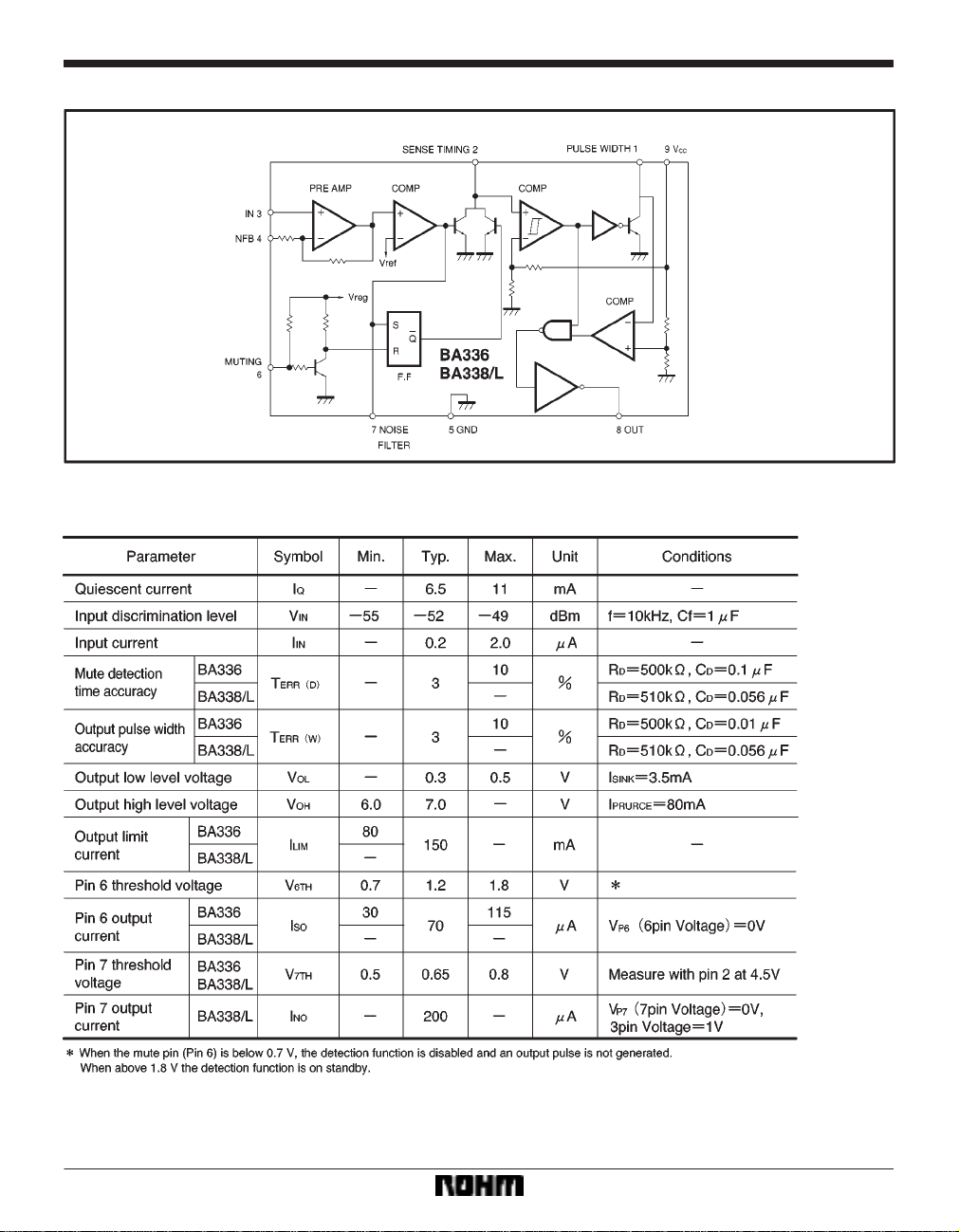
Block diagram
Electrical characteristics (unless otherwise noted, Ta = 25C and V
CC = 9.0V)
727
Page 3
Audio ICs BA336 / BA338 / BA338L
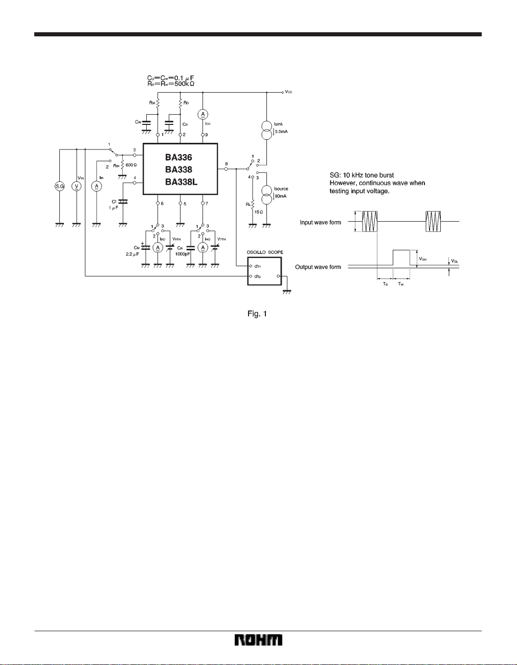
Measurement circuit
728
Page 4

Audio ICs BA336 / BA338 / BA338L
Circuit operation
The BA336 / BA338 / BA338L operates according to
the timing shown in Fig. 2. When the input signal is below
the input decision level, the electrical potential of Pin 2
begins to rise according to the time constant set by C
and RD. When it reaches 1 / 2 of VCC, the comparator
which sets the mute detection time inverts. At this point
the potential of Pin 1 begins to rise according to the time
constant set by C
CC, the pulse width comparator inverts. During the inter-
V
W and RW, and when it reaches 1 / 2 of
val from the inverting of the mute detection time
comparator to the inverting of the pulse width compara-
tor, the output is high. When the power is turned on or
muting is turned off, a reset pulse is generated for a certain period of time (determined by the Pin 6 capacitor),
the internal flip-flop resets, and an output pulse is not
D
generated. When an input signal comes in after this, the
flip-flop resets, mute detection goes on standby , and an
output pulse is obtained with each song gap.If the mute
time is T
pulse width T
Furthermore, T
M, the song detection time TD and the output
W must be selected so that TD TW < TM.
D must be made longer than any periods
of silence in songs.
729
Page 5

Audio ICs BA336 / BA338 / BA338L
Application example
Attached components (see Fig. 3)
(1) Input coupling capacitor CIN and resistor RIN (Pin 3)
This capacitor is for coupling a pre-amp to the
BA336 / BA338 / BA338L.
If the DC level of the pre-amp output is GND, the coupling
capacitor can be omitted. If a coupling capacitor is connected, Pin 3 must be connected to GND through a resistor. If the resistor between Pin 3 and GND is too large, an
offset will occur due to a voltage drop caused by the input
current, and the input decision level will change. We recommend 10kΩ or less. The input decision level of the
BA336 / BA338 / BA338L is highly sensitive at*52dBm.
In the application example, the pre-stage output is divided to adjust the sensitivity and increase the input impedance. Furthermore, the low cutoff frequency fc is determined by the input circuit time constant or the Pin 4
time constant, whichever is smaller . As it is better to determine fc by the Pin 4 C
F when the power is turned on,
we recommend making the time constant of the input circuit larger than that of Pin 4.
(2) DC cutoff capacitor in feedback circuit C
This determines the low cutoff frequency f
F and fC is as follows :
of C
F =
C
If C
F = 1µF, fC 800Hz.
The larger C
F is, the more time it will take for the circuit
0.4πf
1
C (kHz)
(µF)
F (Pin 4)
C. The relation
to stabilize when the power is turned on.
(3) Muting capacitor for power up C
M (Pin 6)
After the power is turned on, this capacitor stops song
selection until the circuit stabilizes. If the value of C
large, a large C
greater than C
cuit to stabilize, select C
The relation between C
M will also be necessary. CM must be
F. Also, if it takes longer for the external cir-
M based on the external circuit.
M and the muting time is as fol-
lows :
TM 30CM (µF)
(4) Noise filter capacitor C
N (Pin 7)
This capacitor prevents errors due to pulse noise.
When an input signal is shorter than the time determined
by T
N = CN (µF) ms (BA338 / BA338L) or TN = 20CN (µF)
ms (BA336), the IC will not respond and an output pulse
will not be generated. If pulse noise appears continuously at the input, the effectiveness of the noise filter will be
decreased. If it is likely that continuous noise will appear ,
attach a discharge resistor R
N y 30kΩ).
(R
N between Pin 7 and GND
There are differences in the noise filter functions of the
BA336 and the BA338 / BA338L. Refer to the section,
“Differences between the noise filters of the BA336 and
BA338 / BA338L”.
F is
730
Page 6

Audio ICs BA336 / BA338 / BA338L
(5) Capacitor CW and resistor RW (Pin 1) for setting output pulse width
The relation between C
W is as follows :
T
T
W is almost independent of the supply voltage.
T
W is small (less than 10kΩ), errors increase.
If R
W, RW and the output pulse width
W 0.69 CW (µF) RW (kΩ) ms
See Fig. 8.
(6) Capacitor C
D and resistor RD (Pin 2) for setting song
gap detection time
The relation between C
D, RD and the detection time TD
(the duration from the point when the input signal goes
below the input decision level to the generation of the output pulse) is as follows :
BA336 :
D = 0.69 CD (µF) RD (kΩ)
T
BA338 / BA338L :
T
D = 0.69 CD (µF) RD (kΩ)
D = =)0.15 CN (µF) RN (kΩ)
T
(The internal resistor R
D is almost independent of the supply voltage.
T
D is small (less than 10kΩ), errors increase.
If R
N is 25 to 100kΩ.)
See Fig. 8.
If a C
N is added in the case of the BA338 / BA338L, its
discharge time will cause T
is when C
N = 0.
Caution is required if T
D to be slightly longer than it
D is made short or a large CN is
used. (See Fig. 9).
Operation notes
(1) The input decision level of the BA336 / BA338 /
BA338L is a highly sensitive -52dBm. This can cause the
output current to return to the input through the common
impedance of the ground line. Be sure to decouple the
power supply line and prevent common impedance with
the ground line. Adding a 0.1µF capacitor between Pin 8
and GND is effective, and we strongly recommend doing
so when high current is used.
(2) The maximum output current of the BA336 /
BA338 / BA338L can be up to 150mA (typical). However,
if left in the current limited state for a long time when using
a high voltage power supply , damage to the IC can result.
Be sure not to exceed the rated power dissipation and the
over-current protection time.
(3) When the BA336 / BA338 / BA338L is input into a
counter IC, make sure the input is above the 2V
F thresh-
old (approximately 1.3V). Otherwise, there is a possibility
that a miscount will occur due to the output pulse generated (approximately 0.5V , see Fig. 4) when the power is
turned on or off.
Differences between the noise filters of the BA336
and BA338 / BA338L
The basic configurations of the BA336 and BA338 /
BA338L are the same, however, the noise filters are different.
BA336 The noise filter only operates from the time the
power is turned on or muting is turned off to the
arrival of the input signal. The power must be
turned off or muting turned on each time an output signal is generated.
BA338 / BA338L The noise filter operates continuously
while the power is on. However, as
noted previously the song gap detection time can change slightly due to
the capacitor C
N connected to the
noise filter pin.
731
Page 7

Audio ICs BA336 / BA338 / BA338L
Electrical characteristic curves
External dimensions (Units: mm)
732
 Loading...