

Page 1

Audio ICs
VSC∗system processor IC
BA1701
The BA1701 is a monolithic audio-compression system controller IC that uses VSC∗.
When used in combination with an analog delay circuit and low-pass filter, it can replay recorded audio at 1 to 2.5 times
the recording speed, without altering the pitch.
Applications
Audio compression systems for tape-based answering machines and learning aids
Features
1) Wide operating voltage range (4.5V to 14V).
2) Built-in two-phase sweep oscillator that can directly
drive BBD.
3) Built-in motor controller is synchronized with the audio compression ratio.
4) Built-in voltage regulator.
Absolute maximum ratings (Ta = 25C)
Recommended operating conditions (Ta = 25C)
∗ VSC is a trademark of The Variable Speech Control Company . This product is manufactured under licence from VSC
Ltd. for use in VSC systems.
861
Page 2

Audio ICs BA1701
Block diagram
Electrical characteristics (unless otherwise noted, Ta = 25C, V
862
CC = 6V, f = 1kHz, and VIN = 1.5VP-P)
Page 3

Audio ICs BA1701
Measurement circuit
863
Page 4
Audio ICs BA1701
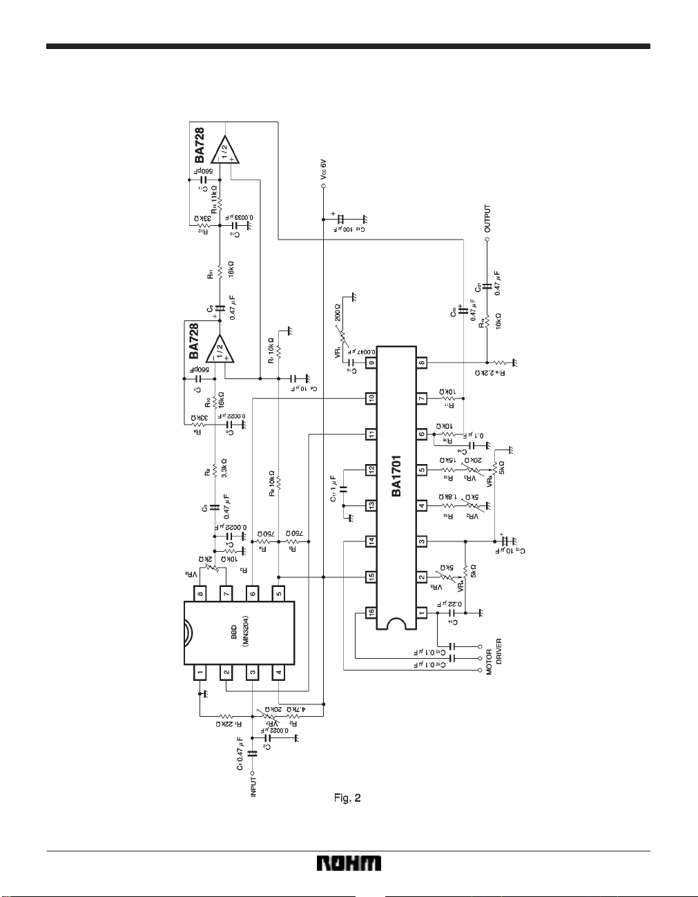
Application example
864
Page 5
Audio ICs BA1701
Circuit operation
(1) System construction
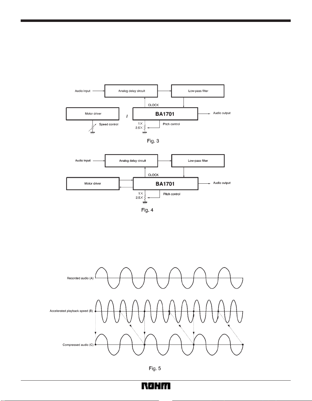
The BA1701 is a monolithic audio-compression system
controller IC that uses VSC.When used in combination
with an analog delay circuit, low-pass filter, and tape
speed controller, it can replay recorded audio at 1 to 2.5
times the recording speed, without altering the pitch (see
Fig. 3).
The BA1701 has a built-in motor driver control circuit that
is synchronized with the pitch control that allows the system to be built with just one pitch control potentiometer
(see Fig. 4).
(2) Principles of audio compression (see Fig. 5)
When recorded audio (A) is replayed at high speed, the
pitch of the audio increases in proportion to the playback
speed (B). By expanding this using an analog delay circuit, a compressed audio signal with the same pitch as
the original recorded signal is obtained (C). Partial audio
dropout occurs when the audio is expanded, but due to
the diffuse nature of speech, the expanded audio does
not sound unnatural to the human ear.
865
Page 6
Audio ICs BA1701
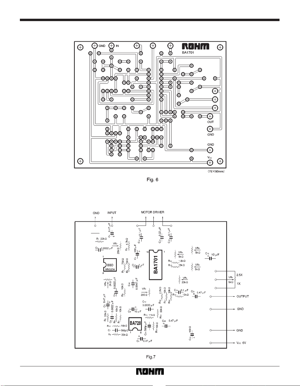
Application board patterns (solder side)
Application board component layout (solder side)
866
Page 7
Audio ICs BA1701
Adjustment procedure
(1) With Rate = 2.5X (VR
pin 12, and adjust VR
6 = GND), apply DC270mV to
1 so that the frequency of the wave-
form on pin 11 is 300kHz.
(2) With Rate = 2.5X, apply DC2.462mV to pin 12, and
adjust VR
2 so that the frequency of the waveform on pin
11 is 12kHz.
(3) Repeat adjustments (1) and (2).
(4) With Rate = 2.5X, adjust VR
3 so that the period of
the waveform on pin 12 is 19ms.
(5) With Rate = 1X (VR
6 = Vref), adjust VR4 so that the
frequency at pin 1 is 300Hz.
(6) With Rate = 2.5X, adjust VR
5 so that the frequency
at pin 1 is 750Hz.
(7) With Rate = 1X, input V
and adjust VR
7 and VR8 so that the output distortion is
IN = 500mV and fIN = 2.5kHz,
minimized.
* If you are not using the motor drive control circuit, adjustments (5) and (6) are not necessary.
Operation notes
(1) Use accurate film capacitors for the VCO time
constant capacitor C
capacitor C
17 (1µF), and the BBD clock time constant ca-
14 (0.22µF), the RAMP time constant
pacitor (0.0047µF).
(2) If the AF output pin (pin 8) has a capacitive load, you
must take precautions to ensure that the BA1701 AF amplifier does not oscillate. We recommend that you insert
R
19 (about 10kΩ) in the signal output line.
(3) T o prevent oscillation, position the earth point of the
BBD clock time constant pin (pin 9) close to the GND pin
(pin 13) (see Fig. 6).
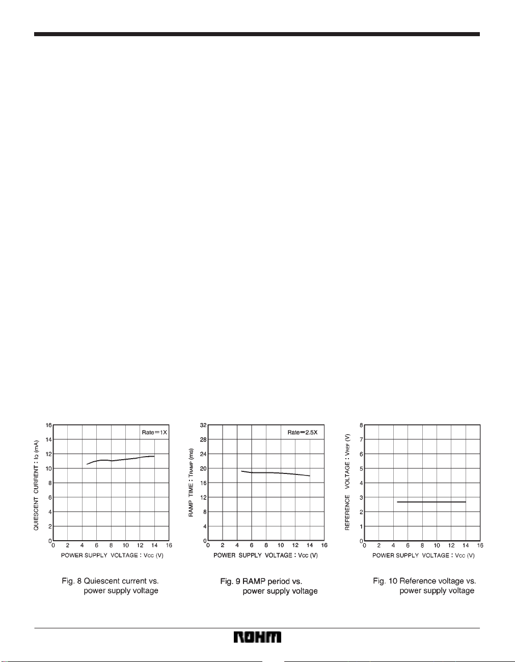
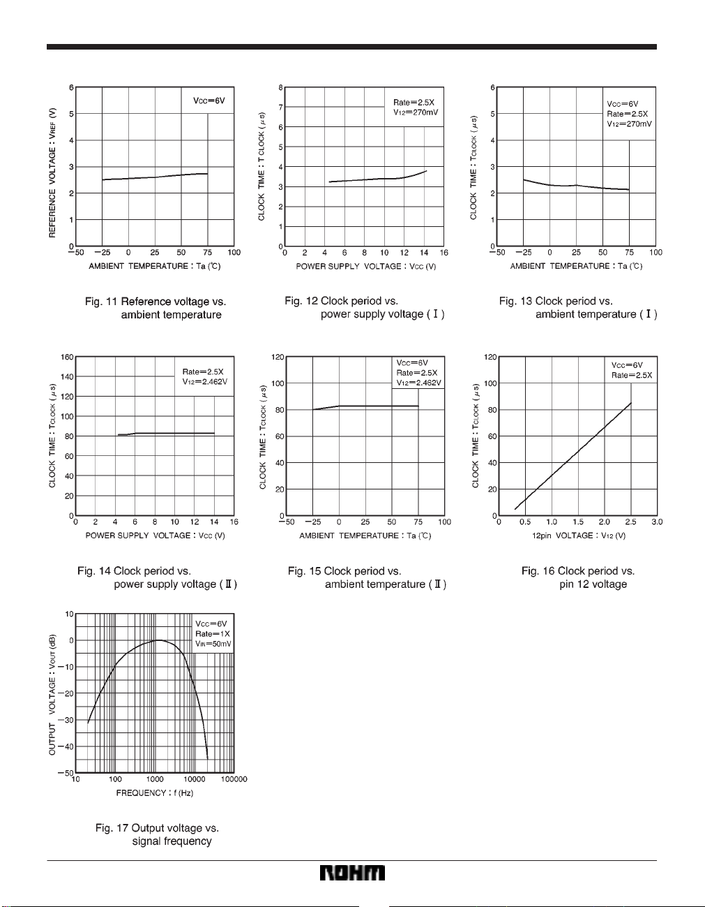
Electrical characteristic curves
867
Page 8
Audio ICs BA1701
868
Page 9
Audio ICs BA1701
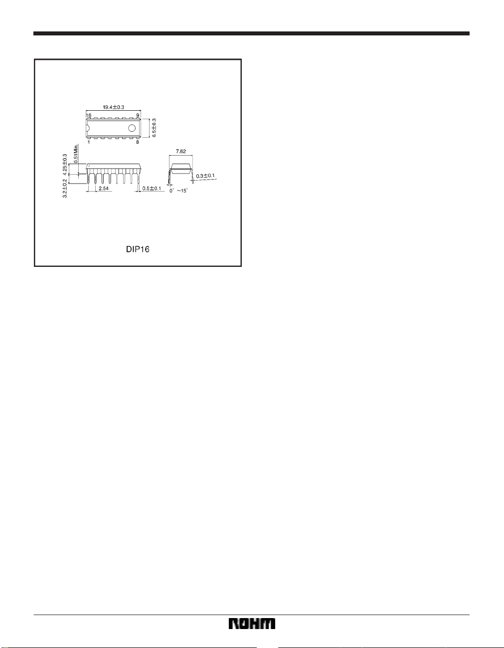
External dimensions (Units: mm)
869
 Loading...