

Page 1

Audio ICs
AM radio / FM IF stereo system IC
BA1442A
The BA1442A is an AM radio and FM IF stereo system IC developed for radio cassette players. The FM circuit is comprised of a differential IF amplifier, a double-balance type quadrature detector, and a PLL-type stereo MPX circuit. The
AM circuit is comprised of a local oscillator, a double-balanced mixer, an IF amplifier, a detector, and an AGC circuit.
Applications
Radio cassette players
Features
1) The “S” curve characteristic of the FM detector can
be used for upper heterodyne (“N” curve) operation.
2) Audio high cut and low cut can be used to improve the
AM fidelity.
3) A reference voltage supply is provided to ensure
good frequency stability in the shortwave bands.
4) Good FM stability.
5) Built-in damping resistor (3.3kΩ) for the quadrature
coil.
6) The FM MPX uses a Laser Locked Loop, making
adjustment of the VCO and addition of external
components unnecessary .
7) Built-in forced monaural function for the MPX (VCO
stops, LED off).
8) VCO of the MPX is switched off during AM operation.
9) The stereo indicator pin has a constant drive current, and a current limiting resistor is not required.
10) Few external components required.
Absolute maximum ratings (Ta = 25C)
Recommended operating conditions (Ta = 25C)
337
Page 2

Audio ICs BA1442A
Block diagram
Pin descriptions
338
Page 3

Audio ICs BA1442A
339
Page 4

Audio ICs BA1442A
340
Page 5

Audio ICs BA1442A
Electrical characteristics (unless otherwise noted, Ta = 25C, VCC = 5V, FM IF MPX: fin = 10.7MHz,
400Hz modulation, 22.5kHz dev (30%), 19kHz 7.5kHz dev (10%)
AM: fin = 1000kHz, fm = 400Hz 30%)
Measurement circuit
341
Page 6

Audio ICs BA1442A
Technical reference materials (unless otherwise noted, Ta = 25C and VCC = 5V)
Circuit operation
(1) The FM IF amplifier is a three-stage differential amplifier. The gain of this stage is approximately 60dB. The
bias for the first-stage amplifier is taken from the bypass
filter (pin 2). This improves the FM stability of the firststage amplifier by reducing noise. The input impedance
is set by a resistor on the chip (330Ω), and can be connected to a ceramic filter.
(2) The FM detector circuit is comprised of a quadrature detector. The IF amplified signal is input to the detector via a limiter amplifier with a gain of 13dB.
(3) The AM mixer is a double-balance type, and has
been designed for low local oscillator leakage. The mixer
bias current is added from Vreg via antenna coil. If you
lower the mixer conversion gain for mid- to high-strength
electric fields, AGC will operate, and for high-strength
electric fields, the input shunt AGC gives good strong-input characteristics.
342
(4) The AM local oscillator circuit consists of a differential positive feedback loop. T o improve the frequency stability , particularly in the SW band, the circuit is operated
with bias referenced to Vreg. T o improve the startup characteristics, a 100Ω resistor is inserted in series with the
tank circuit.
(5) The AM IF amplifier consists of two-stage differential amplifier. Both amplifiers use capacitors to block DC,
so bypass capacitors are not necessary. The first stage
amplifier has AGC. The gain of this stage is 47dB, and
the input impedance is 3kΩ.
(6) AM detector circuit
A built-in envelope detector that uses a minute current
serves as the AM detector. External components are not
required.
Page 7
Audio ICs BA1442A
(7) AM AGC circuit
AGC is applied to the input shunt, mixer , and IF circuits.
The AGC reduces the mixer and IF circuit current, and
according the DC level of the detector output, reduces
the gain to control the output at a fixed level. In addition,
an input shunt is provided to prevent distortion caused by
strong input signals. The AGC pin is also used as the
MPX PLL filter pin. For this reason, when there is no input, the AGC voltage becomes Vreg (pin 19), and when
there is a strong input signal, it is about Vreg - 0.2V.
(8) AM/FM detector circuits
There is one pin for both detector outputs (pin 6), and the
AM /FM switching is done internally. The output impedance is 5kΩ, and the DC output is 1.3V.
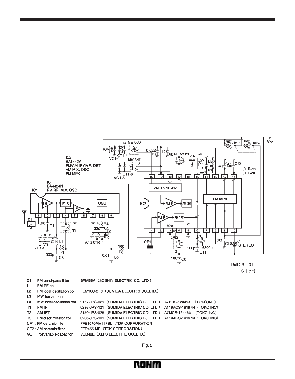
Application example
(9) The FM MPX circuit uses a PLL to recover the stereo. For FM, the input from pin 7 is switched by the decoder and output on pin 11 (L channel) and pin 12 (R
channel). In the case of AM, the input is from pin 8, and
this is output through to pins 11 and 12. The audio fidelity
is improved by the low-pass filter comprised of the capacitor connected between pins 6 and 8 and the input impedance of pin 8 (20kΩ). The input/output gain for both AM
and FM is about 6dB. The VCO has been laser trimmed
on the chip to set its time constant. External components
and re-adjustment are not required.
343
Page 8
Audio ICs BA1442A
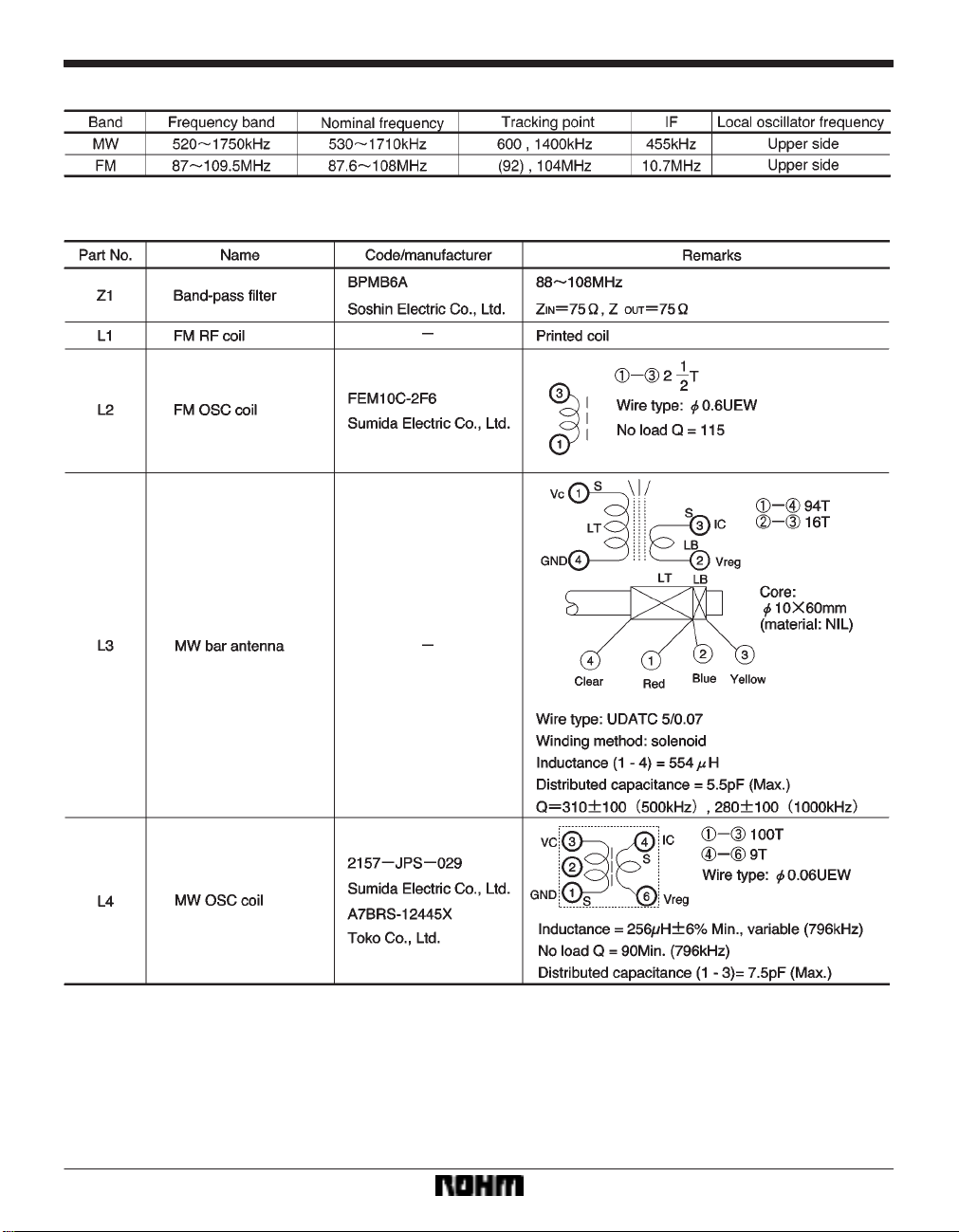
Frequency data
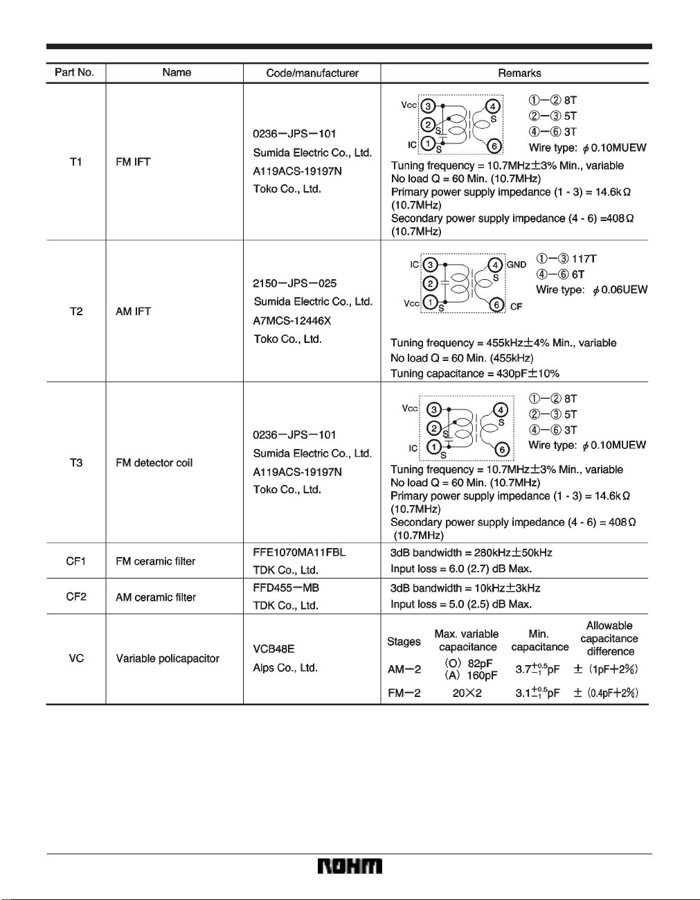
Component data
344
Page 9
Audio ICs BA1442A
345
Page 10
Audio ICs BA1442A
Selecting of attached components and operation notes
Pin 1: FM ceramic filter (CF1)
The input impedance of pin 1 is 330Ω, so it should be connected to a ceramic filter that has an output impedance
of 330Ω. Connect the earth point of the ceramic filter to
the input side GND. In addition, the connection distance
between the ceramic filter and pin 1 should be as short
as possible.
Pin 2: FM IF bypass
This pin is used to ensure stable FM, and it is normally
connected to pin 19 (Vreg). If it is not possible to achieve
stable FM, ground pin 2 via a 0.01µF capacitor. The earth
point in this case will be on the GND side of the FM ceramic filter.
Pin 3: Power supply bypass capacitors (C
7 should be a capacitor with good high-frequency char-
C
acteristics. Connect it between the base of the legs of pin
CC) and pin 5 (GND). The purpose of C8 is ripple rejec-
3 (V
tiun, and it can be connected a little further away.
Pin 4: FM quadrature detector phase-shift coil (T3)
Pin 3 and 4 are connected internally by a 3.3kΩ damping
resistor. The earth point for the phase-shift coil should be
V
CC, so ensure that it is at the same voltage as pin 3 (VCC).
Pin 6: FM detector low-pass filter capacitor (C
This capacitor smooths the 2 10.7MHz (21.4MHz) signal generated by FM quadrature detection, and prevents
leakage of the 10.7MHz signal. The output impedance of
pin 6 (5kΩ) and C
11 form a low-pass filter. Connect the
earth point to a GND other than the input side GND. If you
do not do this, the input carrier will return from the output,
and may result in poor stability .
If the capacitor is too large, poor separation will result.
Pin 7: FM detector output coupling capacitor (C
FM detector output is input to the MPX throngh C
input impedance of pin 7 (100kΩ) and C
pass filter. If the value of C
9 is too low, poor bass region
separation will result.
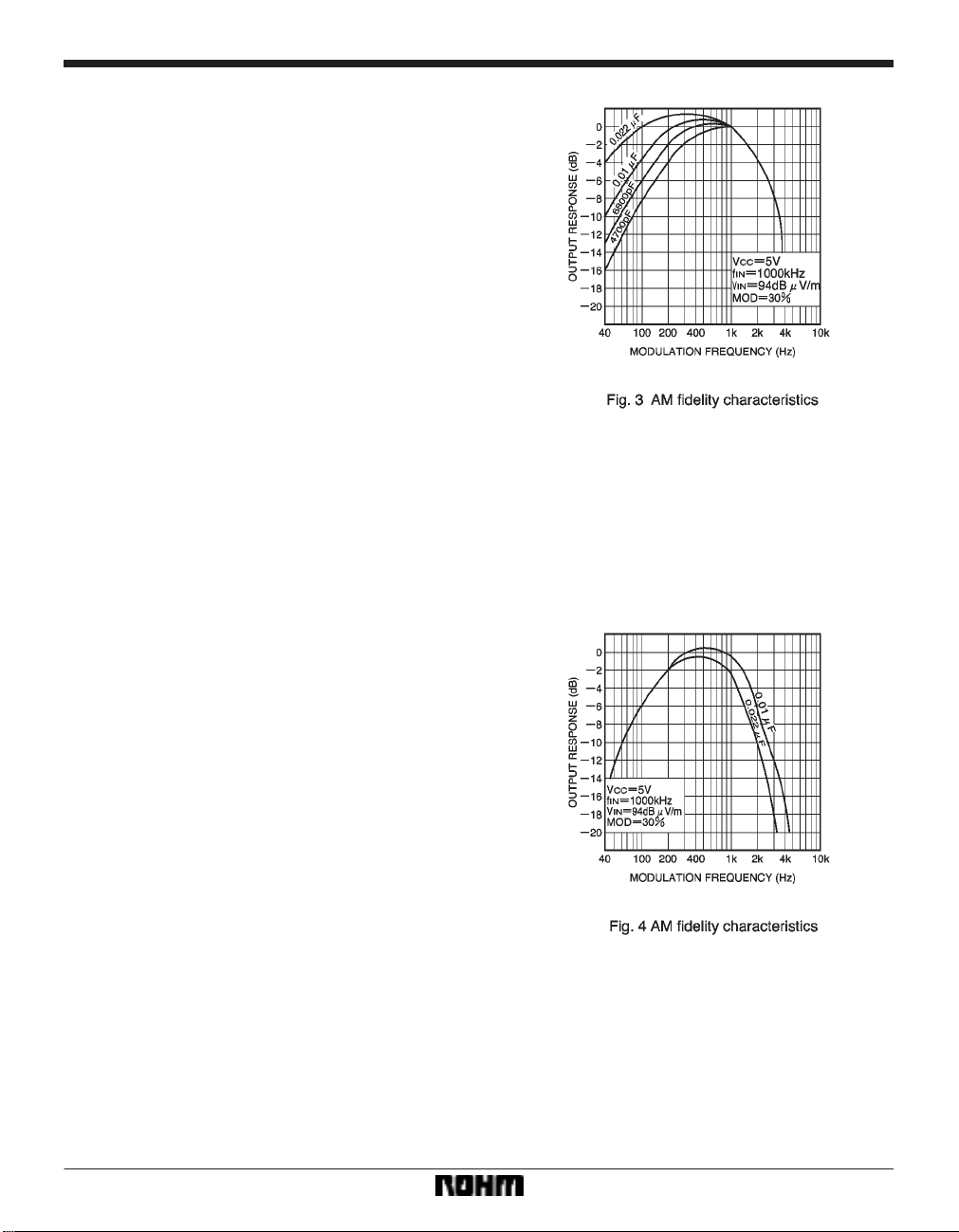
Pin 8: AM detector output coupling capacitor (C
AM detector output is input to the MPX through C
input impedance of pin 8 (20kΩ) and C
filter and improves the AM fidelity. Characteristic curves
for different values of C
10 are given in the graph in Fig. 3.
7 and C8)
11)
9)
9. The
9 form a high-
10)
10. The
10 form a high-pass
Pin 9: AM high-cut capacitor (C
The input impedance of pin 9 (8kΩ) and C
12)
12 form a low-
pass filter. To prevent beat from occurring between carrier leak from the detector output pin and the input signal,
connect a capacitor of about 1000pF, even if not using
high-cut. Connect the earth point to a GND other than the
input side GND. Characteristic curves for different values
of C
12 are given in the graph in Fig. 4.
346
Page 11
Audio ICs BA1442A
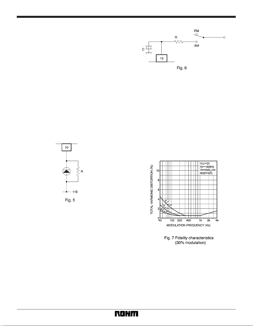
Pin 9: Forced monaural (SW1)
If the voltage on pin 9 goes to 2.2V or higher in FM mode,
forced monaural operation starts (VCO stops, the stereo
indicator goes off, and audio output goes monaural). Do
not apply a voltage to pin 9 that is higher than the voltage
on pin 3 (V
output is output on pin 9, so use a switch to switch pin 9
open circuit in AM mode, as shown in the application circuit example. If you change the voltage on pin 9 during
AM operation, the AGC characteristics will be disturbed.
Pin 10: Stereo indicator
The pin 10 current is fixed at 10mA, so an external current-limiting resistor is not required. If you wish to reduce
the brightness of the LED, connect a resistor in parallel
to reduce the current. If you do not wish to use stereo indication, connect pin 10 directly to the power supply,
however, the current consumption is that same as that
when stereo indication is used. The withstanding voltage
of pin 10 is 9V , so use caution when connecting it to power sources other than the IC power supply.
CC). Also, when in AM mode, the AM detector
Pin 14: PLL filter (C
15, C16, and R4)
PLL loop filter for the MPX. Varying the values of these
components changes the capture range of the PLL, but
can also result in PLL beat, or the PLL going out of lock
due to temperature changes, so do not change these
component values.
Pin 15: Pilot filter and AGC filter (C
17)
Pin 15 is used by both the MPX pilot filter and the AM
AGC filter. Lower values for C
17 will result in increased
THD for bass-region AM audio, and larger values will increase the time required to switch between monaural
and stereo for FM. Characteristic curves for various values of C
17 are given in Figs. 7 to 9.
Pins 11 and 12
De-emphasis capacitors (C
13 and C14)
The output impedance of pins 11 and 12 (5k Ω), and C
and C14 set the de-emphasis time constant (50µsec. for
0.01µF, and 75µsec. for 0.015µF). Do not connect C
and C14 if composite (voice multiplex etc.) signal processing will be performed at the following stage.
Pin 13: AM/FM switching noise reduction filter
Pin 13 is the AM power supply pin. When power is applied, the circuit is in AM mode. By setting a CR time
constant, it is possible to reduce the audible switching
noise that occurs when switching between AM and FM.
Choose the resistor so that the voltage drop across the
resistor is 0.5V max. with respect to the pin 3 (V
not apply a voltage higher than the voltage on pin 3 (V
CC). Do
CC)
to pin 13.
13
13
347
Page 12
Audio ICs BA1442A
Pin 18: AM antenna (L3)
The input impedance of pin 18 is 10kΩ. The AM antenna
earth point is Vreg; make the voltage at pin 18 the same
as the pin 19 (Vreg) potential. If there is a voltage drop,
local oscillator leakage to the mixer output will increase.
Pin 19: Reference power supply bypass capacitors (C
and C19)
Connect the low-frequency bypass capacitor (C
the high-frequency bypass capacitor (C
19).
Pin 20: AM oscillator coil (L4)
T o improve the startup oscillation characteristics, a 100Ω
resistor (built-in) is connected in series with the coil. If the
shortwave oscillation startup characteristics are poor,
connect an additional resistor (47Ω to 100Ω) in series
with the coil. Make the earth point for the oscillator coil pin
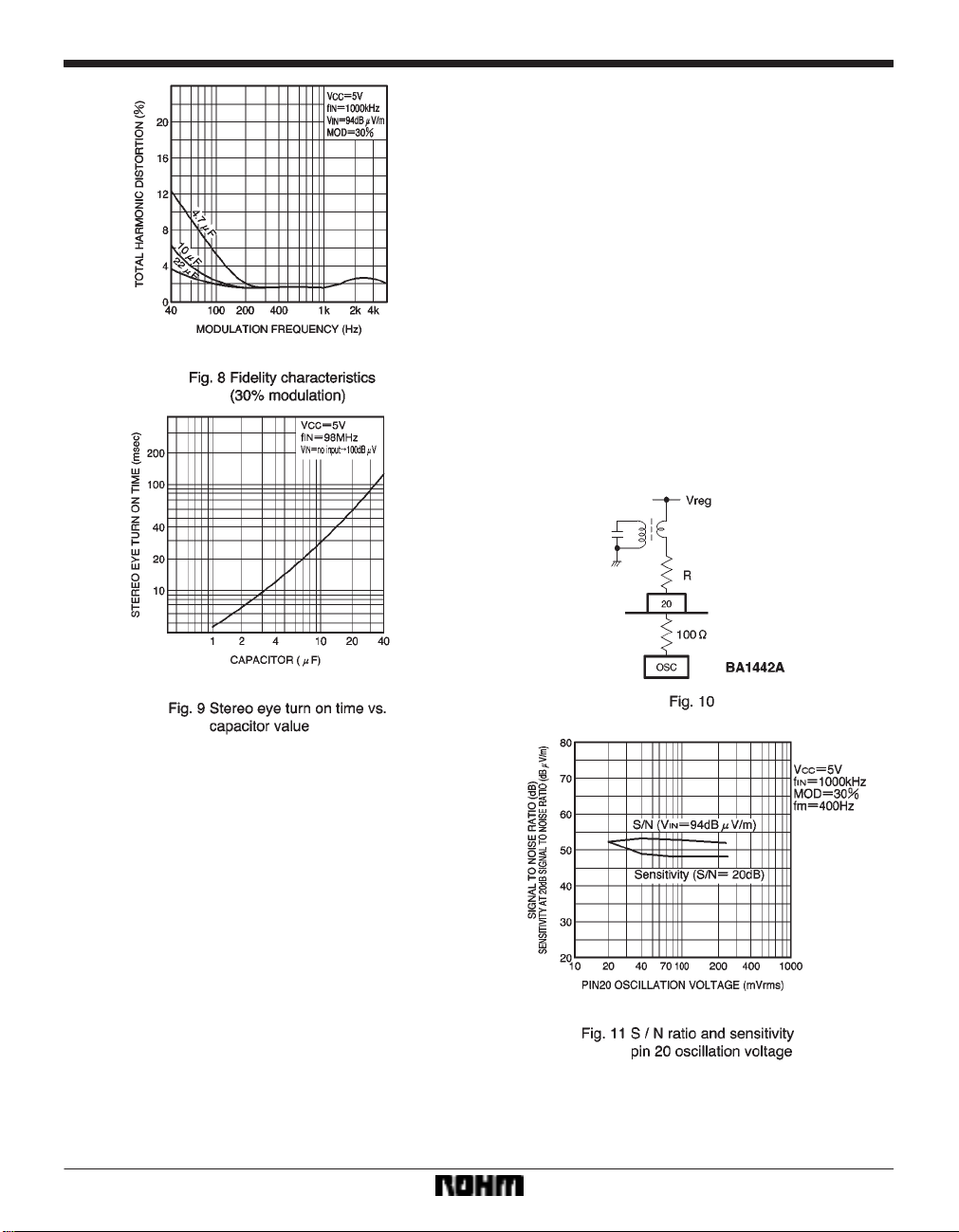
19 (Vreg). The relationship between the S / N ratio and
sensitivity at 20dB S/N against pin 20 oscillation voltage
is shown in Fig. 11.
18) and
18
Pin 16: AM ceramic filter (CF2)
The input impedance of pin 16 is 3kΩ, so it should be connected to a ceramic filter that has an output impedance
of 3kΩ. The connection distance between the ceramic filter and pin 16 should be as short as possible.
Pin 17: AM IFT (T2)
The output impedance of pin 17 is 100kΩ. The IFT earth
point is V
pin 3 (V
CC; make the voltage at pin 17 the same as the
CC) potential. The connection distance between
the IFT and pin 17 should be as short as possible.
348
Page 13
Audio ICs BA1442A
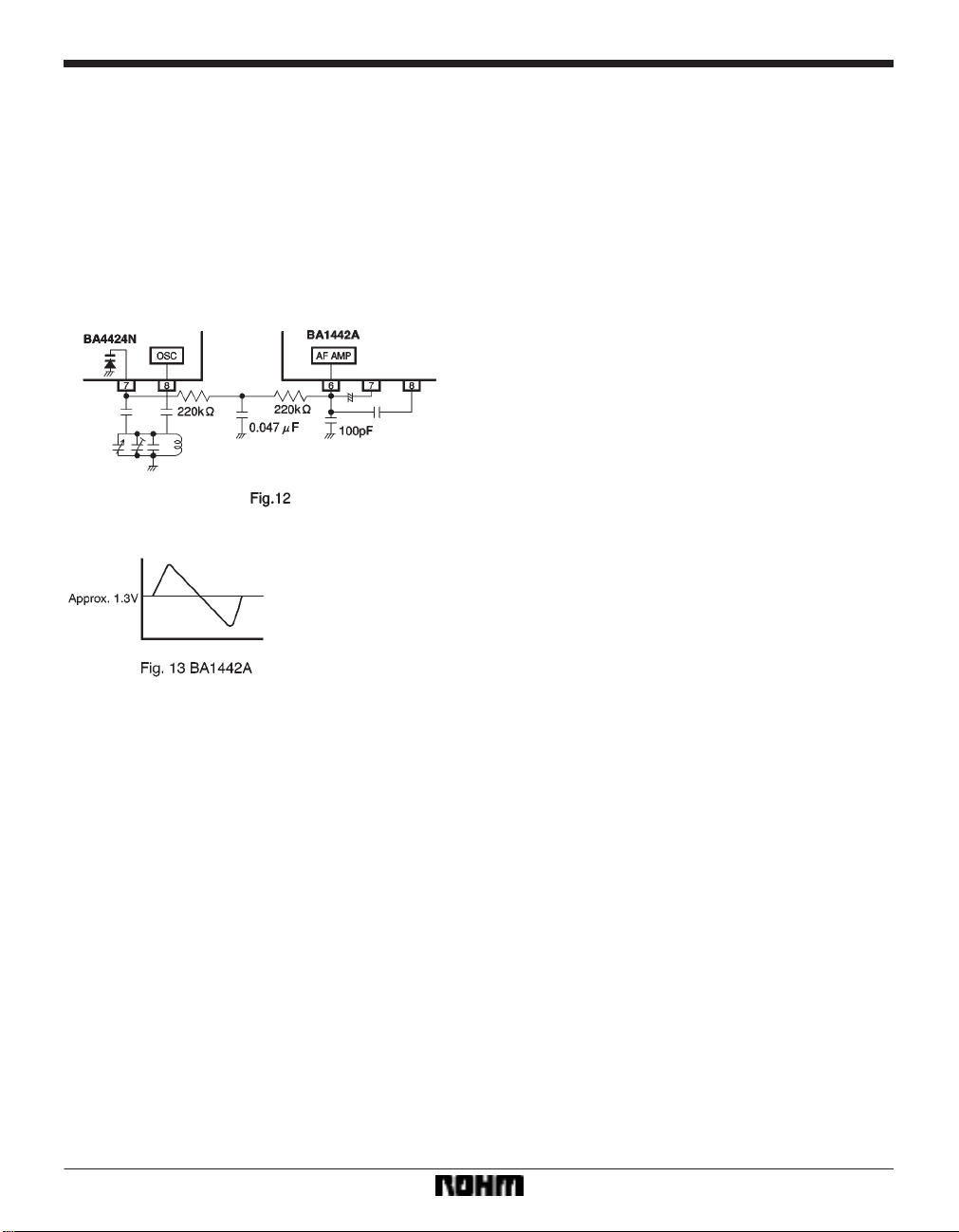
Pin 6: AFC circuit
It is possible to use the pin 6 detector output DC voltage
and apply AFC. Fig. 12 shows an application example
where the BA4424N is used as the FM front end.
Even if you will not use AFC, when recovering the subcarrier phase-modulated composite signal (voice-multiplexed TV) in the next stage, match the oscillator and “S”
curve orientations in the same way as described above.
If they are reversed, the left and right channels of the recovered audio will be reversed.
349
Page 14
Audio ICs BA1442A
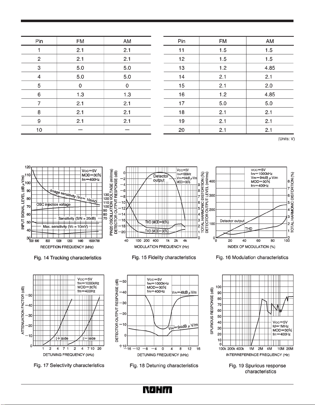
Quiescent pin voltages (VCC = 5V)
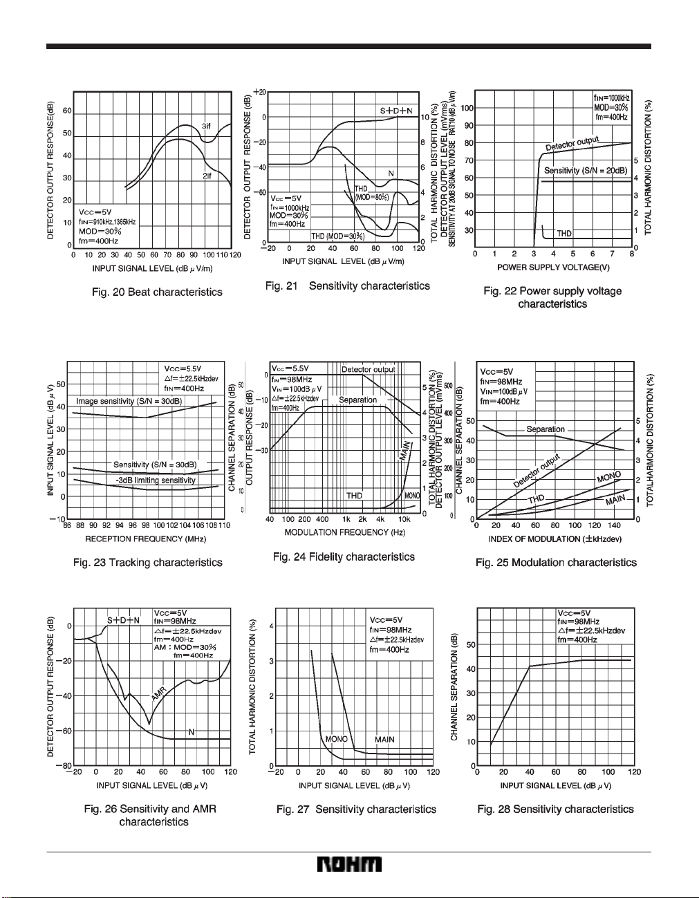
Electrical characteristic curves
MW characteristics
350
Page 15
Audio ICs BA1442A
FM characteristics
351
Page 16
Audio ICs BA1442A
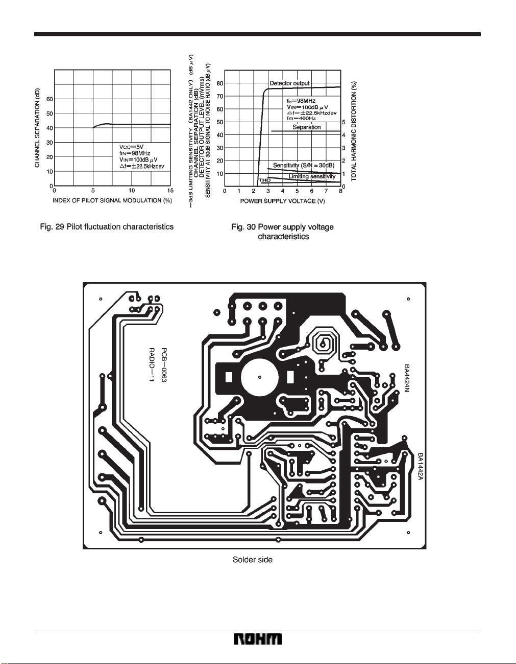
Application board
352
Page 17
Audio ICs BA1442A
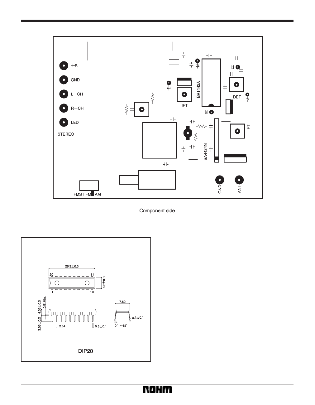
External dimensions (Units: mm)
353
 Loading...