

Datasheet B4041YZ-1.25, B4041YZ-1.225, B4041YM-1.25, B4041YM-1.225, B4041YK-1.25 Datasheet (BAYLI)
...Page 1
Bay Linear, Inc
2418 Armstrong Street, Livermore, CA 94550 Tel: (925) 606-5950, Fax: (925) 940-9556 www.baylinear.com
Precision Micro power Voltage Reference
B4041
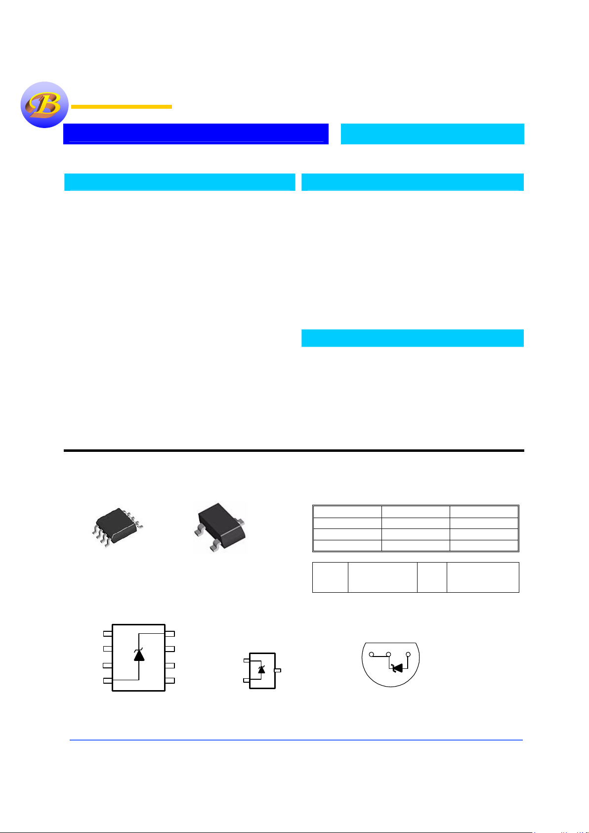
Pin Connection
Ordering Information
Devices Package Temp.
B4041YZ-X TO-92
-40°C to +85°C
B4041YM-X SO-8
-40°C to +85°C
B4041YK-X SOT-23
-40°C to +85°C
Y=
A=100ppm/°C
B=150ppm/°C
X=
1=0.5%
2=1%
3=2%
Description
The B4041 is a two-terminal, temperature compensated,
band-gap voltage reference, which provides a fixed
1.25V output for input currents between 500 µA to
5mA. The bandgap voltage (1.225V) is independently
laser trimmed from the output voltage to achieve a very
low tempco, then the output voltage is laser trimmed to
1.225 volts. This trimming technique and the low
tempco (A grade 50 ppm/ °C) thin film resistor process
gives a very stable device over the full temperature
range. The B4041 is available in the sub-miniature
(3mm × 1.3mm) SOT-23, SO-8 surface mount package,
or TO-92 package. The operating temperature is -40°C
to 85°C.
The Bay Linear B4041 advanced design eliminates the
need for an external stabilized capacitor while insuring
stability with any capacitive load, making them easy to
use.
Features
• Low Temp. Coefficient 50 ppm/◦C
• Operating Current Range of 100µA to 15mA
• Low power 250mW @I
IN
=100mA
• Small package: SOT-23, TO-92, SO-8
• Output Voltage Tolerance of ±0.5%
• Similar Replacement for LM4041
Applications
• Constant Current Source
• Digital Voltmeter
• Power Supply Monitor
• Battery Powered Equipment
• Data Acquisition Systems
• Energy Management
Bay Linear
Inspire the Linear Power
1
2
3
45
6
7
8
_
NC
+
NC
NC
NC
NC
NC
Top View
8-Pin Surface Mount
1
2
Bottom View
TO-92
Plastic Package
3
Front View
2
3
+
_
1
SOT-23
Page 2

Bay Linear, Inc
2418 Armstrong Street, Livermore, CA 94550 Tel: (925) 606-5950, Fax: (925) 940-9556 www.baylinear.com
B4041
ABSOLUTE MAXIMUM RATINGS
Reverse Current............................................................... 20mA Power Dissipation at 25°C
Forward Current .............................................................. 10mA K Package………………300mW
Storage Temperature....................................... -65°C to +150°C Z Package……………….550mW
Lead Temperature Temperature Range…-40°C ≤ T
A
≤ +85°C
K Package .......................................................+215°C
Z Package ........................................................+260°C
ELECTRICAL CHARACTERISTICS
Electrical Characteristics at IIN = 1000µA, and TA = +25°C unless otherwise noted. . Boldface limits apply over
temperature.
Parameter Condition
B4041A-1
Min Type Max
B4041B-1
Min Type Max
B4041C-1
Min Type Max
Unites
Rev; Brek.
Voltage
I
R
=500 µA
1.25 1.25 1.25 V
Rev. Brek
tolerance
I
R
=500 µA
±12
±29
±12
±29
±12
±29
mV
mV
Output
Impedance
0.60
0.3
2
0.9
0.60
0.3
2
1.1
0.60
0.3
2
1.1
Ω
Noise
Voltage
0.1kHz≤f
≤10Hz
15 15 15
µV p-p
Tempco Note 1 100 150 150
ppm/°C
Turn-on
Setting
0.1% of
V
OUT
30 30 30
µSec
Operating
Current
Note 2 0.1 5
15
0.1 5
15
0.1 5
15
mA
Temp.
Range
-40 85 -40 85 -40 85
°C
Parameter Condition
B4041A-2
Min Type Max
B4041B-2
Min Type Max
B4041C-2
Min Type Max
Unites
Rev; Brek.
Voltage
I
R
=500 µA
1.25 1.25 1.25 V
Rev. Brek
tolerance
I
R
=500 µA
±25
±49
±25
±49
±25
±49
mV
mV
Output
Impedance
0.60 2 0.60 2 0.60 2
Ω
Noise
Voltage
0.1kHz≤f
≤10Hz
15 15 15
µV p-p
Tempco Note 1 50 100 150
ppm/°C
Turn-on
Setting
0.1% of
V
OUT
30 30 30
µSec
Operating
Current
Note 2 0.5 5
15
0.5 5
15
0.5 5
15
mA
Temp.
Range
-40 85 -40 85 -40 85
°C
Page 3

Bay Linear, Inc
2418 Armstrong Street, Livermore, CA 94550 Tel: (925) 606-5950, Fax: (925) 940-9556 www.baylinear.com
B4041
Electrical Characteristics
Parameter Condition
B4041A-3
Min Type Max
B4041B-3
Min Type Max
B4041C-3
Min Type Max
Unites
Rev; Brek.
Voltage
I
R
=500 µA
1.25 1.25 1.25 V
Rev. Brek
tolerance
I
R
=500 µA
±50
±74
±50
±74
±50
±74
mV
mV
Output
Impedance
0.60 2 0.60 2 0.60 2
Ω
Noise
Voltage
0.1kHz≤f
≤10Hz
15 15 15
µV p-p
Tempco Note 1 50 100 150
ppm/°C
Turn-on
Setting
0.1% of
VOUT
30 30 30
µSec
Operating
Current
Note 2 0.1 5
15
0.1 5
15
0.1 5
15
mA
Temp.
Range
-40 85 -40 85 -40 85
°C
Note: 1) Three-point measurement guarantees the error band over the specified temperature range.
2) Optimum performance is obtained at currents below 1000 µA.
3) Limits are 100% production tested at 25°C. Limits over temperature are guaranteed through correlation using
B4041 Applications Hints
This device is designed for stable operation and
has no need of an external capacitor between pin
4 and 8. The reference remains stable if a bypass
capacitor is used.
SOT-23
The B4041 in the SOT-23 package has a parasitic
Schottky diode between pin 3 and pin 1. Pin 1 of
SOT-23 must float or be connected to pin 3.
Conventional Shunt Regulator
In a conventional shunt regulator application (see
Figure 1), an external series resister (R
S
) is
connected between the supply voltage and the
B4041. R
S
determines the current that flows
through the load (I
L
) and the reference(IQ). Since
load current and supply voltage may vary, R
S
should be small enough to supply at least the
minimum acceptable I
Q
to the reference even
when the supply voltage is at its minimum and
the load current is at its maximum value. When
the supply voltage is at its maximum and I
L
is at
its minimum, R
S
should be large enough so that
the current flowing through the B4041-x.x is less
than 15mA
RS is determined by the supply voltage (VS), the load and
operating current (I
L
and IQ), reference’s reverse
breakdown voltage (V
R
).
RS = (VS - VR)/(IL+IQ)
V
S
R
S
V
R
I
L
I
Q
IO + I
L
V
O
AS4041
tt
Page 4

Bay Linear, Inc
2418 Armstrong Street, Livermore, CA 94550 Tel: (925) 606-5950, Fax: (925) 940-9556 www.baylinear.com
Advance Information- These data sheets contain descriptions of products that are in development. The specifications are based on the engineering calculations,
computer simulations and/ or initial prototype evaluation.
Preliminary Information- These data sheets contain minimum and maximum specifications that are based on the initial device characterizations. These limits are
subject to change upon the completion of the full characterization over the specified temperature and supply voltage ranges.
The application circuit examples are only to explain the representative applications of the devices and are not intended to guarantee any circuit
design or permit any industrial property right to other rights to execute. Bay Linear takes no responsibility for any problems related to any
industrial property right resulting from the use of the contents shown in the data book. Typical parameters can and do vary in different
applications. Customer’s technical experts must validate all operating parameters including “ Typical” for each customer application.
LIFE SUPPORT AND NUCLEAR POLICY
Bay Linear products are not authorized for and should not be used within life support systems which are intended for surgical
implants into the body to support or sustain life, in aircraft, space equipment, submarine, or nuclear facility applications without
the specific written consent of Bay Linear President.
 Loading...