

Page 1

AX88655 P
5-Port 10/100/1000BASE-T Ethernet Switch
5-Port Gigabit Ethernet Switch with Embedded Memory
Document No.: AX88655-1.0 / V1.0 / Mar, 12,2002
Features
• 5-Port Gigabit Ethernet switch integrating MACs,
packet buffer memory and switching engine with
GMII/MII interface
• Full Duplex 1000 Mbit/s.
• Full and Half Duplex 10/100 Mbit/s
• Supports auto-sensing or manual selection for
speed and duplex capability with an embedded
MPU
• Store-and-forward operation support
• Performs full wire-speed switching with no HOL
blocking
• Broadcast storm control
• Quality-of-Service provisioning on 802.1P tag and
port-pairs with two priority queues
• Embedded 128K Byte SRAM for packet buffer
Product Description
The AX88655 is a 5-Port 10/100/1000 Mbps Ethernet switch with GMII or MII Interface. The switch controller
provides network system manufacturers the ideal platform for building smart and cost-effective backbone switches for
small to medium sized businesses.
The AX88655 5-Port 10/100/100 BASE-T single chip switch controllers combine the benefits of network simplicity,
flexibility and high integration. Its highly integrated feature set enables network system manufacturers to build smart
switches for the fast-growing small to medium business market segment.
Benefits of AX88655 Switches are below.
Ø Simplicity
Provides a smart, simple and low maintenance plug-and-play network interconnect system for small to
medium size businesses
Ø Flexibility
Highly scalable configuration allows system manufacturers to enable or disable a range of features to best meet
their target price point
Ø Integration
Highly integrated design drives down overall switch manufacturing costs.
Target Applications
ü 5-Port Gigabit Layer 2 Switches for workgroup
ü High-port count Layer 2 switches with trunking
ü High performance solution of Ethernet backbone
• Integrated two-way Address-Lookup engine and
table for 4K MAC addresses
• Programmable aging mechanism for the two-way
4K MAC addresses table
• Full-duplex IEEE 802.3x flow control
• Half-duplex back pressure flow control
• Port trunking for high-bandwidth links
• Provides 5 GPIO ports
• Provides EEPROM interface for auto-configuration
• System clock input is one 27MHz Crystal and one
125MHz Oscillator
• 2.5 and 3.3V operations
• 3.3 I/Os and packaged in 256-pin PQFP
This data sheet contains new products information. ASIX ELECTRONICS reserves the rights to modify the product specification without notice. No
liability is assumed as a result of the use of this product. No rights under any patent accompany the sale of the product.
ASIX ELECTRONICS CORPORATION First Released Date: 01/31/2002
4F, NO.8, Hsin Ann Rd., Science-based Industrial Park, Hsin-Chu City, Taiwan, R.O.C.
TEL: 886-3-579-9500 FAX: 886-3-563-9799 http://www.asix.com.tw
Always contact ASIX for possible updates before starting a design.
Page 2
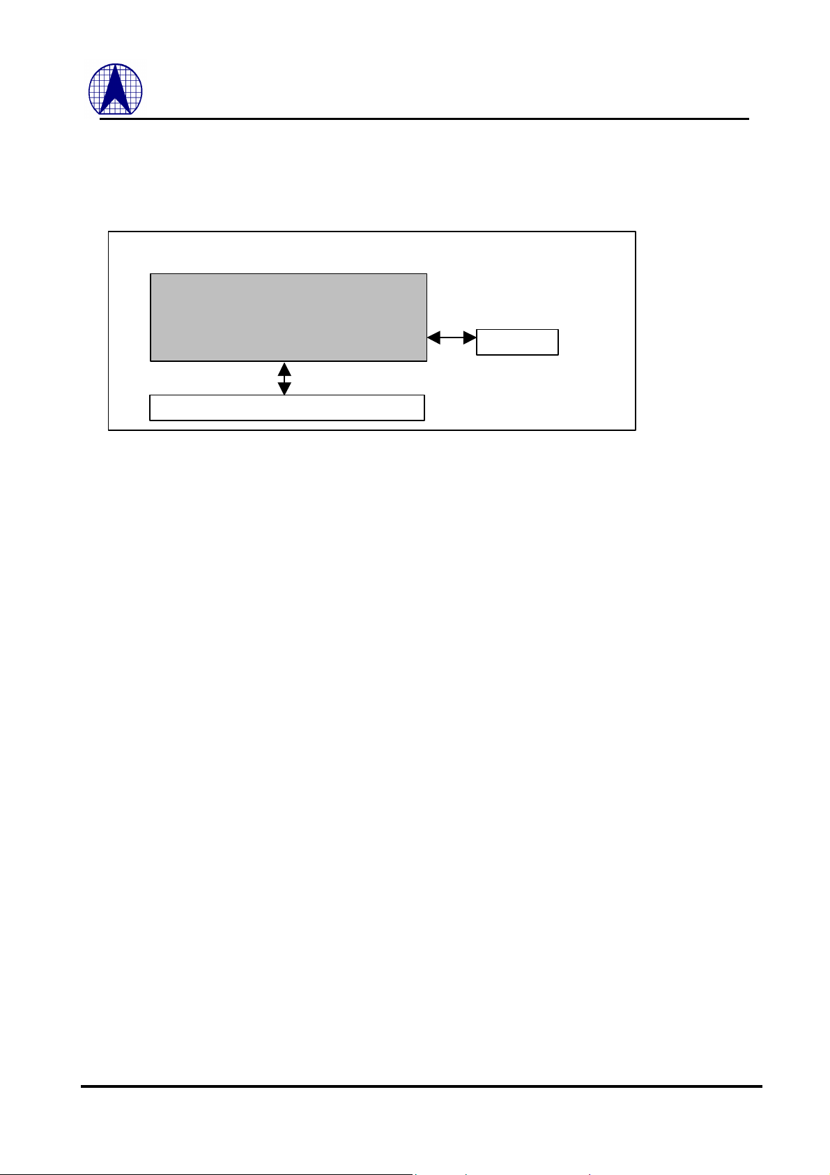
System Block Diagram
Switch Controller
5 * 10/100/1000 Mbps PHYs
AX88655 P 5-Port 10/100/1000BASE-T Ethernet Switch
AX88655P
EEPROM
2
ASIX ELECTRONICS CORPORATION
Page 3

AX88655 P 5-Port 10/100/1000BASE-T Ethernet Switch
CONTENTS
1.0 AX88655 OVERVIEW............................................................................................................. 6
1.1 GENERAL DESCRIPTION ..................................................................................................................... 6
1.2 AX88655 BLOCK DIAGRAM................................................................................................. 6
1.3 PIN CONNECTION DIAGRAM............................................................................................................. 7
2.0 I/O DEFINITION ............................................................................................................................................... 8
2.1 GMII/MII INTERFACE ........................................................................................................................ 8
2.1.1 GMII Interface Port 0 ................................................................................................................................ 8
2.1.2 GMII Interface Port 1 ................................................................................................................................ 9
2.1.3 GMII Interface Port 2 ................................................................................................................................ 9
2.1.4 GMII Interface Port 3 ................................................................................................................................ 9
2.1.5 GMII Interface Port 4 .............................................................................................................................. 10
2.2 MISCELLANEOUS................................................................................................................................. 10
3.0 FUNCTIONAL DESCRIPTION................................................................................... 12
3.1 INTRODUCTION..................................................................................................................................... 12
3.2 PACKET FILTERING AND FORWARDING PROCESS................................................................. 12
3.3 MAC ADDRESS ROUTING, LEARNING AND AGING PROCESS.......................................... 12
3.4 FULL DUPLEX 802.3X FLOW CONTROL..................................................................................... 12
3.5 HALF DUPLEX BACK PRESSURE CONTROL.............................................................................. 12
3.6 MII POLLING......................................................................................................................................... 12
3.7 PORT-BASED QOS: PORT-PAIR ................................................................................................... 13
4.0 REGISTER DESCRIPTIONS......................................................................................... 14
4.1 REGISTER 00.................................................................................................................................................... 14
4.2 REGISTER 01.................................................................................................................................................... 14
4.3 REGISTER 02.................................................................................................................................................... 14
4.4 REGISTER 03.................................................................................................................................................... 15
4.5 REGISTER 04.................................................................................................................................................... 15
4.6 REGISTER 05.................................................................................................................................................... 15
4.7 REGISTER 06.................................................................................................................................................... 15
4.8 REGISTER 07.................................................................................................................................................... 15
4.9 REGISTER 08.................................................................................................................................................... 15
4.10 REGISTER 09.................................................................................................................................................. 15
4.11 REGISTER 0A................................................................................................................................................. 15
4.12 REGISTER 0B................................................................................................................................................. 16
4.13 REGISTER 0C................................................................................................................................................. 16
4.14 REGISTER 0D................................................................................................................................................. 16
4.15 REGISTER 0E ................................................................................................................................................. 16
4.16 REGISTER 0F.................................................................................................................................................. 17
4.17 REGISTER 10.................................................................................................................................................. 17
4.18 REGISTER 11.................................................................................................................................................. 18
4.19 REGISTER 12.................................................................................................................................................. 18
4.20 REGISTER 13.................................................................................................................................................. 18
4.21 REGISTER 14.................................................................................................................................................. 18
3
ASIX ELECTRONICS CORPORATION
Page 4

AX88655 P 5-Port 10/100/1000BASE-T Ethernet Switch
5.0 ELECTRICAL SPECIFICATION AND TIMING..................................... 19
5.1 ABSOLUTE MAXIMUM RATINGS................................................................................................... 19
5.2 GENERAL OPERATION CONDITIONS............................................................................................ 19
5.3 DC CHARACTERISTICS..................................................................................................................... 19
5.4 AC SPECIFICATIONS........................................................................................................................... 20
5.4.1 X_IN Signal Timing.................................................................................................................................. 20
5.4.2 Reset Signal Timing ................................................................................................................................. 20
5.4.3 GMII Transmit/Receive Signals Timing.................................................................................................... 21
5.4.4 100 Mbps MII Transmit/Receive Signals Timing ...................................................................................... 22
5.4.5 10 Mbps MII Transmit/Receive Signals Timing ........................................................................................ 23
6.0 PACKAGE INFORMATION.......................................................................................... 25
APPENDIX A: SYSTEM APPLICATIONS............................................................... 26
A.1 AX88655 AS 5-PORT SOHO HIGH TRAFFIC POWER USER SWITCH ...................................................................... 26
A.2 AX88655 AS 5-PORT SMART SWITCH (DIP SWITCH CONFIGURABLE)................................................................. 26
A.3 AX88655 FOR 10/100MBPS ETHERNET BACKBONE.......................................................................................... 27
A.4 AX88655 FOR SUPER SERVER TRUNKING APPLICATION.................................................................................... 27
APPENDIX B: DESIGN NOTE.............................................................................................. 28
B.1 USING MII I/F CONNECTS TO MAC.................................................................................................................. 28
APPENDIX C: WEIGHT SETTING FOR QOS..................................................... 29
DEMONSTRATION CIRCUIT (A) : AX88658 SMART SWITCH... 30
4
ASIX ELECTRONICS CORPORATION
Page 5

AX88655 P 5-Port 10/100/1000BASE-T Ethernet Switch
FIGURES
FIG-1 AX88655 BLOCK DIAGRAM...........................................................................................................6
FIG-2 AX88655 PIN DIAGRAM................................................................................................................... 7
5
ASIX ELECTRONICS CORPORATION
Page 6
AX88655 P 5-Port 10/100/1000BASE-T Ethernet Switch
1.0 AX88655 Overview
1.1 General Description
The AX88655 Gigabit switch controller supports five 10/100/1000 Mbps ports in wire-speed operation. The AX88655
Gigabit switch controller provides five 10/100/1000 Ethernet ports with GMII/MII interface. For each ports, the
AX88655 supports GMII (802.3ab) interface with full-duplex operation at Gigabit speed, full- or half-duplex operation
at 10/100 Mbps speed and polls the status of PHYs with an embedded MPU.
Embedded 128K bytes SRAM as a packet buffer operates with an internal 90MHz clock. For efficient utilization of the
packet buffer, there are 1024 128-byte page-links totally in the buffer.
The device supports 4K internal MAC addresses which are shared by all ports with an embedded 32K byte SSRAM. The
learning/routing engine is implemented with a two-way hash/linear algorithm to reduce possibility of routing collision.
Basically the AX88655 supports non-blocking wire speed forwarding rate and no Head-of-Line (HOL) blocking issue.
The AX88655 provides two flow-control mechanisms to avoid loss of data: an optional jamming based backpressure flow
control in the half-duplex operation and IEEE 802.3x in the full-duplex mode.
To support Quality of Service (QoS), each output port has two priority queues and their assignment can be based on the
802.1p priority field or Port-Pair setting. Each output port retrieves the frames from the shared buffer based on queuing
and sends them to the transmitting (Tx) FIFO.
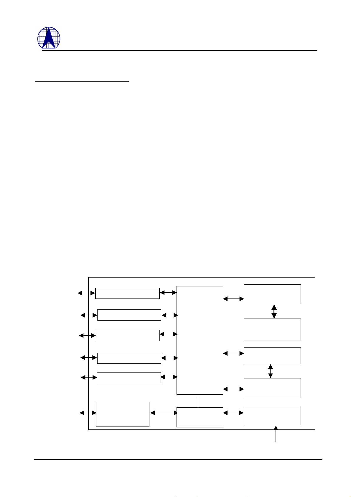
1.2 AX88655 Block Diagram
GMII PHY
GMII PHY
GMII PHY
GMII PHY
GMII PHY
GPIO
10/100/1000 MAC
10/100/1000 MAC
10/100/1000 MAC
10/100/1000 MAC
10/100/1000 MAC
General Purpose
I/O Interface (GPIO)
High Speed
Switch Fabric
Configuration
Logic
Routing /Learning
Engine
Address Look-up Table
Buffer Manager
Packet
Buffer
EEPROM
Interface
Fig-1 AX88655 Block Diagram
6
ASIX ELECTRONICS CORPORATION
Page 7
TX_EN0
AVDD25D
TX_CLK1
RX_DV1
NC
TXD1[1]
NC
TXD1[2]
VSS
RXD1[6]
NC
COL1
AVDD25A
NC
TXD0[4]
RXD1[4]
NC
VSS
NC
VDD25
VSS
NC
AVSS25D
RXD1[2]
RXD1[1]
NC
TXD1[3]
GTX_CLK1
RX_CLK1
FILTER
NC
NC
VSS
NC
TXD0[6]
VDD33
RXD1[7]
X_IN
NC
RXD1[5]
TXD0[5]
VSS
NC
NC
VSS
VSS
AVSS25A
NC
VSS
RXD1[3]
CRS1
X_OUT
TXD1[4]
NC
VDD25
VDD25
NC
VSS
TXD0[7]
AVBB25
NC
RXD1[0]
TXD1[1]
VSS
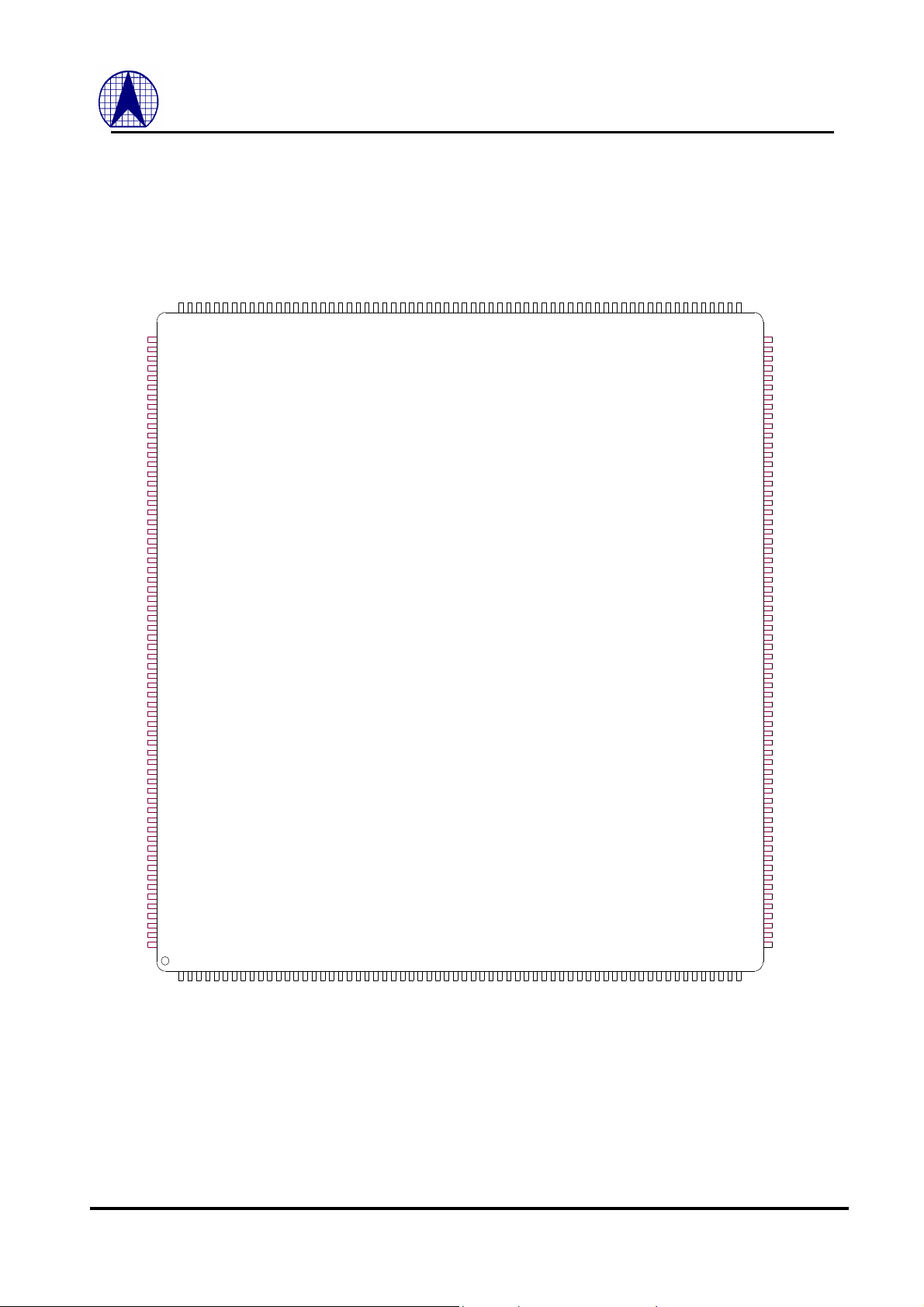
1.3 Pin Connection Diagram
VSS
VSS
VSS
NC
VDD25
NC
NC
NC
NC
NC
NC
NC
NC
NC
NC
VSS
VDD25
NC
NC
VSS
VSS
VSS
VSS
NC
NC
NC
NC
VSS
VSS
VSS
NC
VDD25
NC
NC
NC
NC
NC
NC
NC
NC
NC
NC
VSS25
VDD25
CRS0
COL0
RXD0[0]
RXD0[1]
RXD0[2]
RXD0[3]
RXD0[4]
RXD0[5]
RXD0[6]
RXD0[7]
RX_CLK0
RX_DV0
VSS
GTX_CLK0
VDD25
TX_CLK0
TXD0[0]
TXD0[1]
TXD0[2]
TXD0[3]
NC
NC
NC
NC
VSS
VSS
VSS
VSS
191
190
192
188
189
187
186
193
194
195
196
197
198
199
200
201
202
203
204
205
206
207
208
209
210
211
212
213
214
215
216
217
218
219
220
221
222
223
224
225
226
227
228
229
230
231
232
233
234
235
236
237
238
239
240
241
242
243
244
245
246
247
248
249
250
251
252
253
254
255
256
1
2
185
7
5
8
3
6
4
NC
184
9
VDD25
NC
182
183
10
GPIO3
VSS
GPIO0
GPIO2
GPIO4
GPIO1
NC
NC
NC
175
179
178
177
176
174
173
181
180
10/100/1000Mbps
Switch Controller
12
11
14
13
20
19
15
16
17
18
AX88655 P 5-Port 10/100/1000BASE-T Ethernet Switch
VSS
SYSCLK
169
168
NC
167
MDC
MDIO
166
165
SDC
164
SDIO
VDD25
163
162
GCLK
161
NC
172
/RST
VDD33
171
170
AX88655P
Ethernet
29
21
23
24
22
25
31
27
30
26
32
28
VSS
VSS
/GCLK_EN
/SYSCLK_EN
158
160
159
157
35
34
33
36
SID4
156
37
SID3
155
38
SID1
SID2
154
39
153
40
SID0
VDD25
152
151
41
42
TX_EN4
VSS
150
149
43
44
TXD4[6]
TXD4[7]
148
147
45
46
TXD4[4]
TXD4[5]
TXD4[3]
145
144
146
47
48
49
TXD4[0]
TXD4[1]
TXD4[2]
143
142
141
51
52
50
TX_CLK4
GTX_CLK4
VSS
VDD25
139
138
140
137
54
55
53
56
RX_DV4
RXD4[7]
RX_CLK4
135
136
134
57
59
58
RXD4[5]
RXD4[4]
RXD4[6]
132
133
131
62
61
60
RXD4[3]
RXD4[2]
130
129
128
127
126
125
124
123
122
121
120
119
118
117
116
115
114
113
112
111
110
109
108
107
106
105
104
103
102
101
100
99
98
97
95
94
93
92
91
90
89
88
87
86
85
84
83
82
81
80
79
78
77
76
75
74
73
72
71
70
69
68
67
66
65
64
63
96
RXD4[1]
RXD4[0]
COL4
CRS4
VDD25
VSS
TX_EN3
TXD3[7]
TXD3[6]
TXD3[5]
TXD3[4]
TXD3[3]
TXD3[2]
TXD3[1]
TXD3[0]
TX_CLK3
VDD25
GTX_CLK3
VSS
RX_DV3
RX_CLK3
RXD3[7]
RXD3[6]
RXD3[5]
RXD3[4]
RXD3[3]
RXD3[2]
RXD3[1]
RXD3[0]
COL3
CRS3
VDD25
VSS25
TX_EN2
TXD2[7]
TXD2[6]
TXD2[5]
TXD2[4]
TXD2[3]
TXD2[2]
TXD2[1]
TXD2[0]
TX_CLK2
VDD25
GTX_CLK2
VSS
RX_DV2
RX_CLK2
RXD2[7]
RXD2[6]
RXD2[5]
RXD2[4]
RXD2[3]
RXD2[2]
RXD2[1]
RXD2[0]
COL2
CRS2
VDD25
VSS25
TX_EN1
TXD1[7]
TXD1[6]
TXD1[5]
Fig-2 AX88655 Pin Diagram
7
ASIX ELECTRONICS CORPORATION
Page 8
AX88655 P 5-Port 10/100/1000BASE-T Ethernet Switch
When TX_EN0 is asserted, data on TXD0[7:0] are
transmitted onto PHY. TX_EN0 is synchronous to GTX_CLK0 in
T
Synchronous to the rising of GTX_CLK0 in
T mode. And synchronous to rising edge of TX_CLK0 in
and TXD0[3:0] are
Active high to indicate that there is collision
Active high if there is carrier on medium. In half
CRS0 is also asserted during transmission and
Active high to indicate that data presented on
is running at 1000/100/10
T mode respectively. RX_DV0 and RXD0[7:0] are synchronous
Data received by the PHY are presented on RXD0 and
d in
T
2.0 Pin Descriptions
2.0 I/O Definition
The following terms describe the AX88655 pin-out:
All pin names with the “/” suffix are asserted low.
The following abbreviations are used in following Tables.
I Input PU Pull Up
O Output PD Pull Down
I/O Input/Output P Power Pin
OD Open Drain
2.1 GMII/MII Interface
2.1.1 GMII Interface Port 0
Signal Name I/O Pin No. Description
GTX_CLK0 O
TX_EN0
TXD0[7:0]
TX_CLK0 I/PD
COL0 I/PD
CRS0 I/PD
RX_DV0 I 248
RX_CLK0 I 247
RXD0[7:0]
O
O
I/PD
250
5
4 – 1,
256 – 253
252
238
237
246 - 239
125MHz Clock Output: it is a continuous 125 MHz clock output to
giga-PHY operating at 1000BASE-T. That is, it is a timing reference
for TX_EN0 and TXD0[7:0]
Transmit Enable:
1000BASE-T mode and synchronous to TX_CLK0 in 10/100BASEmode.
Transmit Data:
1000BASE10/100BASE-T mode.
MII Transmit Clock Input: TX_EN0
synchronous to the rising edge of this clock in 10/100BASE-T mode.
Collision Detect:
occurred in half duplex mode. In full duplex mode COL0 is always low.
Carrier Sense:
duplex mode
asynchronous to any clock.
Receive Data Valid:
RXD0[7:0] is valid and synchronous to RX_CLK0.
Receive Clock Input: 125, 25 and 2.5 MHz
BASEto rising edge of this clock.
Receive Data:
synchronous to RX_CLK0. RXD0[3:0] is vali
10/100/1000BASE-T and RXD[7:4] is valid only in 1000BASEmodes.
8
ASIX ELECTRONICS CORPORATION
Page 9
AX88655 P 5-Port 10/100/1000BASE-T Ethernet Switch
2.1.2 GMII Interface Port 1
Signal Name I/O Pin No. Description
GTX_CLK1 O
TX_EN1
TXD1[7:0]
TX_CLK1 I/PD
COL1 I/PD
CRS1 I/PD
RX_DV1 I 55
RX_CLK1 I 54
RXD1[7:0]
O
O
I/PD
57
68
67 – 60
59
45
44
53 - 46
125MHz Clock Output: Please references section 2.1.1.
Transmit Enable: Please references section 2.1.1.
Transmit Data: Please references section 2.1.1.
MII Transmit Clock Input: Please references section 2.1.1.
Collision Detect: Please references section 2.1.1.
Carrier Sense: Please references section 2.1.1.
Receive Data Valid: Please references section 2.1.1.
Receive Clock Input: Please references section 2.1.1.
Receive Data: Please references section 2.1.1.
2.1.3 GMII Interface Port 2
Signal Name I/O Pin No. Description
GTX_CLK2 O
TX_EN2
TXD2[7:0]
TX_CLK2 I/PD
COL2 I/PD
CRS2 I/PD
RX_DV2 I 82
RX_CLK2 I 81
RXD2[7:0]
O
O
I/PD
84
95
94 – 87
86
72
71
80 - 73
125MHz Clock Output: Please references section 2.1.1.
Transmit Enable: Please references section 2.1.1.
Transmit Data: Please references section 2.1.1.
MII Transmit Clock Input: Please references section 2.1.1.
Collision Detect: Please references section 2.1.1.
Carrier Sense: Please references section 2.1.1.
Receive Data Valid: Please references section 2.1.1.
Receive Clock Input: Please references section 2.1.1.
Receive Data: Please references section 2.1.1.
2.1.4 GMII Interface Port 3
Signal Name I/O Pin No. Description
GTX_CLK3 O
TX_EN3
TXD3[7:0]
TX_CLK3 I/PD
COL3 I/PD
CRS3 I/PD
RX_DV3 I 109
RX_CLK3 I 108
RXD3[7:0]
O
O 121 – 114
I/PD
111
122
113
99
98
107 - 100
125MHz Clock Output: Please references section 2.1.1.
Transmit Enable: Please references section 2.1.1.
Transmit Data: Please references section 2.1.1.
MII Transmit Clock Input: Please references section 2.1.1.
Collision Detect: Please references section 2.1.1.
Carrier Sense: Please references section 2.1.1.
Receive Data Valid: Please references section 2.1.1.
Receive Clock Input: Please references section 2.1.1.
Receive Data: Please references section 2.1.1.
9
ASIX ELECTRONICS CORPORATION
Page 10
This is a clock source of PLL. The
ded
generated by
PHY Management Data Input and
EEPROM Serial Clock. (Note: It is
MPU can identify the switch and PHYs with this ID.
The 5 GPIOs can be programmed for special
. (Note: The function is not released to user normally.
2.1.5 GMII Interface Port 4
Signal Name I/O Pin No. Description
GTX_CLK4 O
TX_EN4
TXD4[7:0]
TX_CLK4 I/PD
COL4 I/PD
CRS4 I/PD
RX_DV4 I 136
RX_CLK4 I 135
RXD4[7:0]
O
O 148 – 141
I/PD
138
149
140
126
125
134 - 127
125MHz Clock Output: Please references section 2.1.1.
Transmit Enable: Please references section 2.1.1.
Transmit Data: Please references section 2.1.1.
MII Transmit Clock Input: Please references section 2.1.1.
Collision Detect: Please references section 2.1.1.
Carrier Sense: Please references section 2.1.1.
Receive Data Valid: Please references section 2.1.1.
Receive Clock Input: Please references section 2.1.1.
Receive Data: Please references section 2.1.1.
2.2 Miscellaneous
Signal Name I/O Pin No. Description
X_IN I 35
X_OUT O 36
GCLK I 161
SYSCLK I 168
/GCLK _EN I/PU
/SYSCLK_EN I/PU
FILTER I 40
/RST I 170
MDIO I/O/PU
MDC O 166
SDIO I/O/PU
SDC I/O/PU
SID[4:0] I/PD
GPIO[4:0] I/O/PU 180 - 176
157
158
165
163
164
I/PD
I/PD
I/UP
I/UP
156,
155,
154,
153,
152
Crystal or OSC 27MHz Input:
PLL will generate a 90MHz internal clock.
Crystal 27MHz Output: This pin should be floating with single-en
external clock.
OSC 125MHz Input: 125MHz Clock for GMII
System Clock Input: 85 ~ 90MHz Clock for switch kernel
GCLK Enable: 0) use GCLK; 1) Reserved
System Clock Enable: 0) use SYSCLK; 1) 90MHz
internal PLL circuit from X_IN clock source.
FILTER: For internal PLL circuit use.
Reset: Active Low
Station Management Data In/Out:
Output.
Station Management Data Clock Out: PHY Management Clock.
EEPROM Data In/Out: EEPROM Serial Data Input and Output.
EEPROM Data Clock In/Out:
output pin if the embedded MPU is active; otherwise as input pin)
Switch ID:
Default is “00011b”.
General Purpose I/O:
application
Please contact with ASIX directly if any requirement)
AX88655 P 5-Port 10/100/1000BASE-T Ethernet Switch
10
ASIX ELECTRONICS CORPORATION
Page 11
8, 9, 41, 15, 16,
NC N/A
17, 21, 23, 24,
25, 26, 27, 28,
29, 30, 31, 32,
43, 167, 172,
VDD33 I 34, 171,
VDD25 P 7, 22,
VSS P 6, 10, 11, 12,
AVBB25 P 37
AVDD25A P 38
AVSS25A P 39
AVDD25D P 42
AVSS25D P 41
173, 174, 175,
183, 184, 189,
190, 191, 192,
196, 198, 199,
200, 201, 202,
203, 204, 205,
206, 207, 210,
211, 216, 217,
218, 219, 223,
225, 226, 227,
228, 229, 230,
231, 232, 233,
234
58, 70, 85,
97, 112, 124,
139, 151, 162,
182, 197, 209,
224, 236, 251
13, 18, 19, 20,
33, 56, 69,
83,96, 110,
123, 137, 150,
157, 159, 160,
167, 169, 181,
185, 186, 187,
188, 193, 194,
195, 208, 212,
213, 214, 215,
220, 221, 222,
235, 249
AX88655 P 5-Port 10/100/1000BASE-T Ethernet Switch
NC: No Connect.
3.3V +/-5% Supply Voltage.
2.5V +/-5% Supply Voltage.
Ground
Ground for PLL
2.5V +/-5% Supply Voltage for PLL.
Ground for PLL
2.5V +/-5% Supply Voltage for PLL.
Ground for PLL
11
ASIX ELECTRONICS CORPORATION
Page 12

AX88655 P 5-Port 10/100/1000BASE-T Ethernet Switch
3.0 Functional Description
3.1 Introduction
In general, the AX88655 device is a highly integrated Layer 2 switch. It supports five 10/100/1000 ports with on-chip
MACs. It also supports integrated switching logic, packet queuing memory and packet storage memory. The AX88655
is capable of routing-and-forwarding packets at wire speed on all ports regardless of packet size.
It is a low cost solution for five ports Gigabit Ethernet backbone switch design. No CPU interface is required; After power
on reset, AX88655 provide an auto load configuration setting function through a 2 wire serial EEPROM interface to
access external EEPROM device, and AX88655 can easily be configured to support trunking, QoS, IEEE 802.3x flow
control threshold setting, broadcast storm control ...etc functions. An overview of AX88658’s major functional blocks is
shown in Fig-1.
3.2 Packet Filtering and Forwarding Process
The switch use simple store-and-forward algorithm as packet switching method. After receives incoming packets, the
packets will be stored to the embedded memory first. The AX88655 searches in the Address-Lookup Table with DA of
the packet. The packet will be forward to its destination port, if this packet’s DA hits; otherwise this packet will be
broadcasted. Of course, only good packets will be forward. Conditions of good packets are below:
1. CRC is correct.
2. 64 Bytes < PacketLength < 1518/1522 Bytes
3. Not local packets, That is, it is a local packets if its SourcePort is its DestinationPort.
4. Not PAUSE or other control packets.
5. Not the same trunking group.
3.3 MAC Address Routing, Learning and Aging Process
The switch supports 4K MAC entries for switching. Two-way dynamic address learning is performed by each good
unicast packet is completely received. And linear/XOR hash algorithm of the static address learning is achieved by
EEPROM configuration. On the other hand, the routing process is performed whenever the packet’s DA is captured. If
the DA can not get a hit result, the packet is going to broadcast.
Only the learned address entries are scheduled in the aging machine. If one station does not transmit any packet for a
period of time, the belonging MAC address will be kicked out from the address table. The aging out time can be program
automatically through the EEPROM configuration. (Default value is 300 seconds)
3.4 Full Duplex 802.3x Flow Control
In full duplex mode, AX88655 supports the standard flow control mechanism defined in IEEE 802.3x standard. It
enables the stopping of remote node transmissions via a PAUSE frame information interaction. When space of the packet
buffer is less than the initialization setting threshold value, AX88655 will send out a PAUSE-ON packet with pause time
equal to “xFFF” to stop the remote node transmission. And then AX88655 will send out a PAUSE-OFF packet with
pause time equal to zero to inform the remote node to retransmit packet if has enough space to receive packets.
3.5 Half Duplex Back Pressure Control
In half duplex mode, AX88655 provide a backpressure control mechanism to avoid dropping packets during network
conjection situation. When space of the packet buffer is less than the initialization setting threshold value, AX88655 will
send a JAM pattern in the input port when it senses an incoming packet, thus force a collision to make the remote node
transmission back off and will effectively avoid dropping packets. And then AX88655 will not send out a JAM packet
any more if has enough space to receive one packet.
3.6 MII Polling
The AX88655 supports PHY management through the serial MDIO/MDC interface. That is, the AX88655 access related
12
ASIX ELECTRONICS CORPORATION
Page 13

AX88655 P 5-Port 10/100/1000BASE-T Ethernet Switch
register of PHYs via MDIO/MDC interface after power on reset. The AX88655 will periodically and continuously poll
and update the link status and link partner’s ability which include speed, duplex mode, and 802.3x flow control capable
status of the connected PHY devices through MDIO/MDC serial interface.
3.7 Port-Based QoS: Port-Pair
AX88655 provides 4 Port-Pairs for bandwidth management. Users can assign any two ports as one Port-Pair with
internal registers basically. Any packets will put the high priority queue of the Port-Pair when send the packets each
other. That is, two ports of each Port-Pair will obtain more bandwidth than other ports when congestion.
In addition, one port can be as the highest priority port if one All_Bit of a Port-Pair is active. That is, user can assign
format of the Port-Pair as OnePort-to-All and every packets of the OnePort will put in the high priority transmit queue of
other ports.
13
ASIX ELECTRONICS CORPORATION
Page 14

AX88655 P 5-Port 10/100/1000BASE-T Ethernet Switch
4.0 Register Descriptions
Registers Table Summary:
Address 15 14 13 12 11 10 9 8 7 6 5 4 3 2 1 0 Default
00 H
01 H
02 H
03 H
04 H
05 H
06 H
07 H
08 H
09 H
0A H
0B H
0C H
0D H
0E H Res. PTO MPL Reserved SR SP NSB Reserved QoS[1:0] AE HM Res. 8880 H
0F H
10 H Reserved Trunk30[2:0]
11 H
12 H
13 H
14 H
Notes: 1. The word “Reserved” = “Res.” on the above table.
Notes: 2. Care must be taken that the “Reserved” registers should keep the default value always. Change of any reserved
value may be resulting in unpredictable conditions.
Notes: 3. The registers can be accessed by internal MPU only. The MPU will read in configuration table, located on
EEPROM at somewhere address, and programs the above registers when every time power on or after system
reset.
Reserved RxFlowCtrl[4:0] Reserved TxFlowCtrl[4:0] 0000 H
PortPair1[7:0] PortPair0[7:0] 0000 H
PortPair3[7:0] PortPair2[7:0] 0000 H
LowQueueWeight[3:0]
HighQueueWeight[3:0] MaxStorm
Reserved MaxAge[8:0] 1865 H
Reserved LowQueueFlowCtrlMark[9:0] 0010 H
MaxJam[5:0] HighQueueFlowCtrlMark[9:0] 2810 H
Reserved hw_LowQueueDiscardLimit[9:0] 0070 H
Reserved hw_HighQueueDiscardLimit[9:0] 0070 H
Reserved lw_LowQueueDiscardLimit [9:0] 1060 H
Reserved 0000 H
Reserved 0000 H
Reserved 0000 H
Reserved 0000 H
Reserved 0000 H
Reserved 0000 H
Reserved
Reserved 7777 H
Reserved 7777 H
lw_HighQueueDiscardLimit [9:0] 1060 H
Reserved 00C0 H
1215 H
4.1 Register 00
BIT R/W DESCRIPTION
15:0
R/W
Reserved
4.2 Register 01
BIT R/W DESCRIPTION
15:0
R/W
Reserved
4.3 Register 02
BIT R/W DESCRIPTION
15:13
R/W
Reserved
14
ASIX ELECTRONICS CORPORATION
Page 15

AX88655 P 5-Port 10/100/1000BASE-T Ethernet Switch
12:8
7:5
4:0
R/W
R/W
R/W
FlowCtrlEnable for MAC’s receive part of Port[4:0] are configured by internal 8051
0: not identify PAUSE frames by receive part of MAC
1: can identify PAUSE frames. That is, PauseTimer of MAC will be active.
Reserved
FlowCtrlEnable for MAC’s transmit part of Port[4:0] are configured by internal 8051
0: not send PAUSE frames or JAM
1: send PAUSE frames for full-duplex when the packet buffer is empty.
send JAM frames for half-duplex when the packet buffer is empty.
4.4 Register 03
BIT R/W DESCRIPTION
15:0
R/W
Reserved
4.5 Register 04
BIT R/W DESCRIPTION
15:0
R/W
Reserved
4.6 Register 05
BIT R/W DESCRIPTION
15:0
R/W
Reserved
4.7 Register 06
BIT R/W DESCRIPTION
15:0
R/W
Reserved
4.8 Register 07
BIT R/W DESCRIPTION
15:0
R/W
Reserved
4.9 Register 08
BIT R/W DESCRIPTION
15:0
R/W
Reserved
4.10 Register 09
BIT R/W DESCRIPTION
15:0
R/W
Reserved
4.11 Register 0A
BIT R/W DESCRIPTION
15
14:12
R/W
R/W
All_Bit of PortPair #1 when QoS[0] is high
Port_ID of PortPair #1 when QoS[0] is high
15
ASIX ELECTRONICS CORPORATION
Page 16

AX88655 P 5-Port 10/100/1000BASE-T Ethernet Switch
11
10:8
7
6:4
3
2:0
R/W
R/W
R/W
R/W
R/W
R/W
All_Bit of PortPair #1 when QoS[0] is high
Port_ID of PortPair #1 when QoS[0] is high
All_Bit of PortPair #0 when QoS[0] is high
Port_ID of PortPair #0 when QoS[0] is high
All_Bit of PortPair #0 when QoS[0] is high
Port_ID of PortPair #0 when QoS[0] is high
4.12 Register 0B
BIT R/W DESCRIPTION
15
14:12
11
10:8
7
6:4
3
2:0
R/W
R/W
R/W
R/W
R/W
R/W
R/W
R/W
All_Bit of PortPair #3 when QoS[0] is high
Port_ID of PortPair #3 when QoS[0] is high
All_Bit of PortPair #3 when QoS[0] is high
Port_ID of PortPair #3 when QoS[0] is high
All_Bit of PortPair #2 when QoS[0] is high
Port_ID of PortPair #2 when QoS[0] is high
All_Bit of PortPair #2 when QoS[0] is high
Port_ID of PortPair #2 when QoS[0] is high
4.13 Register 0C
BIT R/W DESCRIPTION
15:12
11:10
9:0
R/W
R/W
R/W
WeightForLowQue: Weight for low priority queues when QoS is active (see Appendix C)
Reserved
LowWaterMark of low priority queues when drop packets
4.14 Register 0D
BIT R/W DESCRIPTION
15:12
11:10
9:0
R/W
R/W
R/W
WeightForHighQue: Weight for high priority queues when QoS is active (see Appendix C)
Maximum number of broadcast frames that can be accumulated in each input frame buffer.
00: disable broadcast storm control
01: 32 frames
10: 48 frames
11: 64 frames
LowWaterMark of high priority queues when drop packets
4.15 Register 0E
BIT R/W DESCRIPTION
15
14
13
12:11
10
R/W
R/W
R/W
R/W
R/W
Reserved
802.3x Flow control frame recognition control
0: check for MAC control frame DA MAC address in addition to the MAC control type field
1: check only the MAC control type field
Setting for maximum length of packet that received
0: 1518 byte
1: 1522 byte
Reserved
Software Reset (Only reset the switch kernel)
0: active
1: disable
16
ASIX ELECTRONICS CORPORATION
Page 17

resolution of the normal address aging is (64 M* MaxAge[8:0]) /
9
8
7:5
4:3
2
1
0
R/W
R/W
R/W
R/W
R/W
R/W
R/W
AX88655 P 5-Port 10/100/1000BASE-T Ethernet Switch
Back-off algorithm selection
0: disable. Device will perform the IEEE standard exponential back off algorithm when a
collision occurs.
1: enable. When collisions occur, the MACs will back off up to 7 slots.
0: stop generate JAM patterns after some collision that is defined by MaxJam[5:0]
1: Never stop back-pressure
Reserved
QoS selection
00: disable QoS function
01: Port-Pair Priority algorithm
10: 802.1p
AgingEnable Switch Table Entry Aging Control. Only the dynamically learned addresses
will be aged. All explicit entries will not age. The aging time is programmed in register 0F.
0: disable. The table aging process is disabled.
1: enable. The table aging process is enabled and a hardware process ages every
dynamically learned table entry.
Hash algorithm selection
0: XOR mapping
1: Linear mapping
Reserved
4.16 Register 0F
BIT R/W DESCRIPTION
15:9
8:0
R/W
R/W
Reserved
MaxAge. This is a seven-bit register containing unsigned integer for determining the
address-aging timer. The
FreqencyOfSystemClock. Default value is 300 seconds.
4.17 Register 10
BIT R/W DESCRIPTION
15:13
12:10
9:0
R/W
R/W
R/W
Reserved
Trunking selection for Port[3:0]
000: disable trunking
001: disable trunking
010: one 2-Port Trunking for Port[1:0]
011: one 2-Port Trunking for Port[1:0]
100: one 2-Port Trunking for Port[3:2]
101: one 4-Port Trunking
110: two 2-Port Trunkings for Port[3:2] and Port[1:0]
111: one 4-Port Trunking
Reserved
17
ASIX ELECTRONICS CORPORATION
Page 18

AX88655 P 5-Port 10/100/1000BASE-T Ethernet Switch
4.18 Register 11
BIT R/W DESCRIPTION
15:10
9:0
R/W
R/W
Reserved
LowWaterMarkForFlowCtrl. This is a ten-bit register containing unsigned integer for
transmit queues whether generate PAUSE-ON or not.
4.19 Register 12
BIT R/W DESCRIPTION
15:10
9:0
R/W
R/W
MaxJam. This is a six-bit register containing unsigned integer for determining the JAM
counter whether generate JAM or not.
HighWaterMarkForFlowCtrl. This is a ten-bit register containing unsigned integer for
transmit queues whether generate PAUSE-OFF or not.
4.20 Register 13
BIT R/W DESCRIPTION
15:10
9:0
R/W
R/W
Reserved
HighWaterMark of low priority queues when drop packets
4.21 Register 14
BIT R/W DESCRIPTION
15:10
9:0
R/W
R/W
Reserved
HighWaterMark of high priority queues when drop packets
18
ASIX ELECTRONICS CORPORATION
Page 19

AX88655 P 5-Port 10/100/1000BASE-T Ethernet Switch
5.0 ELECTRICAL SPECIFICATION AND TIMING
5.1 Absolute Maximum Ratings
Description SYM Min Max Units
Operating Temperature Ta 0 +70
Storage Temperature Ts -55 +150
Supply Voltage Vcc -0.3 +4.0 V
Input Voltage Vin -0.3 Vdd+0.5 V
Output Voltage Vout -0.3 Vdd+0.5 V
Lead Temperature (soldering 10 seconds maximum) Tl -55 +220
Note: Stress above those listed under Absolute Maximum Ratings may cause permanent damage to the device. Exposure
to Absolute Maximum Ratings conditions for extended period, adversely affect device life and reliability
5.2 General Operation Conditions
Description SYM Min Max Units
Operating Temperature Ta 0 +70
Supply Voltage Vdd +3.0 +3.6 V
°C
°C
°C
°C
5.3 DC Characteristics
(Vdd=3.0V to 3.6V, Vss=0V, Ta=0°C to 70°C)
Description SYM Min Max Units
Low Input Voltage Vil Vss-0.3 0.8 V
High Input Voltage Vih 2 Vdd+0.5 V
Low Output Voltage Vol 0.4 V
High Output Voltage Voh 2.4 V
Input Leakage Current 1 (Note 1) Iil1 10 uA
Input Leakage Current 2 (Note 2) Iil1 500 uA
Output Leakage Current Iol 10 uA
Description SYM Min Tpy Max Units
Power Consumption Pc TBD mA
Note:
1. All the input pins without pull low or pull high.
2. Those pins had been pull low or pull high.
19
ASIX ELECTRONICS CORPORATION
Page 20

5.4 AC specifications
5.4.1 X_IN Signal Timing
X_IN
Tr Tf Tlow
Symbol
Tcyc CYCLE TIME
Thigh CLK HIGH TIME
Tlow CLK LOW TIME
Tr/Tf CLK SLEW RATE
5.4.2 Reset Signal Timing
SYSCLK
/RST
Symbol
Trst Reset pulse width
Thigh
Tcyc
Description Min Typ. Max Units
Description Min Typ. Max Units
AX88655 P 5-Port 10/100/1000BASE-T Ethernet Switch
20 ns
8 10 12 ns
8 10 12 ns
1 - 4 ns
10 - - SYSCLK
20
ASIX ELECTRONICS CORPORATION
Page 21

AX88655 P 5-Port 10/100/1000BASE-T Ethernet Switch
5.4.3 GMII Transmit/Receive Signals Timing
T0 T1
GTX_CLK
T2 T3
TX_EN
TXD[7:0]
Symbol
T0 GTX_CLK Clock Cycle Time 7.998
T1 GTX_CLK Clock High Time 4 ns
T2 TX_EN and TXD data setup to GTX_CLK rising edge 2.5 ns
T3 TX_EN and TXD data hold from GTX_CLK rising edge 0.5 ns
Description Min Typ. Max Units
T4 T5
RX_CLK
T6 T7
RX_DV
RXD[7:0]
Symbol
T4 RX_CLK Clock Cycle Time 7.998 8 8.002
T5 RX_CLK Clock High Time 4 ns
T6 RX_DV and RXD data setup to RX_CLK rising edge 2.5 ns
T7 RX_DV and RXD data hold from RX_CLK rising edge 0.5 ns
Description Min Typ. Max Units
8 8.002
ns
ns
21
ASIX ELECTRONICS CORPORATION
Page 22

AX88655 P 5-Port 10/100/1000BASE-T Ethernet Switch
5.4.4 100 Mbps MII Transmit/Receive Signals Timing
T0 T1
TX_CLK
T2 T2
TX_EN
T3 T3
TXD[3:0]
Symbol
T0 TX_CLK Cycle Time 39.996 40 40.004
T1 TX_CLK High Time 14 20 26 ns
T2 TX_CLK rising edge to TX_EN Delay 7.440 21.760
T3 TX_CLK rising edge to TXD Delay 3.410 13.320
Description Min Typ. Max Units
T4 T5
RX_CLK
T6 T6
RX_CRS
RX_DV
T7 T7
RXD[3:0]
Symbol
T4 RX_CLK Clock Cycle Time 39.996 40 40.004 ns
T5 RX_CLK Clock High Time 14 20 26 ns
T6 RX_CLK rising edge to RX_DV and RX_CRS Delay 3.0 13.0 ns
T7 RX_CLK rising edge to RXD Delay 3.0 13.0 ns
Description Min Typ. Max Units
ns
ns
ns
22
ASIX ELECTRONICS CORPORATION
Page 23

AX88655 P 5-Port 10/100/1000BASE-T Ethernet Switch
5.4.5 10 Mbps MII Transmit/Receive Signals Timing
T0 T1
TX_CLK
T2 T2
TX_EN
T3 T3
TXD[3:0]
Symbol
T0 TX_CLK Cycle Time 399.96 400 400.04
T1 TX_CLK High Time 14 20 26 ns
T2 TX_CLK rising edge to TX_EN Delay 7.440 21.760
T3 TX_CLK rising edge to TXD Delay 3.410 13.320
Description Min Typ. Max Units
T4 T5
RX_CLK
T6 T6
RX_CRS
RX_DV
T7 T7
RXD[3:0]
Symbol
T4 RX_CLK Clock Cycle Time 399. 96 400 400. 04 ns
T5 RX_CLK Clock High Time 140 200 260 ns
T6 RX_CLK rising edge to RX_DV and RX_CRS Delay 3.0 13.0 ns
T7 RX_CLK rising edge to RXD Delay 3.0 13.0 ns
Description Min Typ. Max Units
ns
ns
ns
23
ASIX ELECTRONICS CORPORATION
Page 24

AX88655 P 5-Port 10/100/1000BASE-T Ethernet Switch
24
ASIX ELECTRONICS CORPORATION
Page 25

AX88655 P 5-Port 10/100/1000BASE-T Ethernet Switch
6.0 PACKAGE INFORMATION
Hd
D
pin 1
He
E
b
e
A2 A1
L1
L
θ
MILIMETER SYMBOL
MIN. NOM MAX
A1
A2
b
D
E
e
Hd
He
L
L1
θ
0.25
0.45
0 7
3.4
0.16
28.00
28.00
0.4
30.6
30.6
1.3
0.75
25
ASIX ELECTRONICS CORPORATION
Page 26

AX88655 P 5-Port 10/100/1000BASE-T Ethernet Switch
Appendix A: System Applications
A.1 AX88655 as 5-Port SOHO high traffic power user switch
AX88655P
Switch Controller
1 GMII PHY
Quad GMII PHY
Or
4 GMII PHYs
I/O Port for
Configuration
From PC
SEEPROM for save
Configuration
A.2 AX88655 as 5-Port Smart switch (DIP switch configurable)
LEDs or General
Serial Output via
AX88655P
Switch Controller
5 * 10/100/1000Mbps PHYs
Configuration Serial
In via GPIO
EEPROM
DIP SW
26
ASIX ELECTRONICS CORPORATION
Page 27

AX88655 P 5-Port 10/100/1000BASE-T Ethernet Switch
A.3 AX88655 for 10/100Mbps Ethernet Backbone
WAN Router
Using 2 Gigabit Ports Up-link and Trunking form a 12.8G Non-blocking backbone
5-port Gigabit switch
AX88655P
Switch Controller
16*10/100Mbps
+2*1000Mbps
Ethernet Switch
16*10/100Mbps
+2*1000Mbps
Ethernet Switch
A.4 AX88655 for Super Server Trunking Application
5-port Gigabit switch
AX88655 P
Switch Controller
Super Server with
2 * Gigabit Ethernet
Cards Trunking
27
ASIX ELECTRONICS CORPORATION
Page 28

AX88655 P 5-Port 10/100/1000BASE-T Ethernet Switch
Appendix B: Design Note
B.1 Using MII I/F connects to MAC
Using MII interface to connect to MAC type device application for AX88655 is illustrated bellow.
10K
Gnd
COL0
TX_EN0
TX_CLK0
TXD0[3:0]
CRS0
RX_DV0
RX_CLK0
RXD0[3:0]
AX88655 / Switch AX88195 / MAC
Note: 1. The MAC needs to run at full-duplex mode.
2. Care must be taken that the receive side has enough setup and/or hold time
3. Some kind of CPU with embedded MAC can also refer to this example
25MHz
Clock
COL
CRS
RX_DV
RX_CLK
RXD[3:0]
RX_ER
TX_EN
TX_CLK
TXD[3:0]
TX_ER
28
ASIX ELECTRONICS CORPORATION
Page 29

AX88655 P 5-Port 10/100/1000BASE-T Ethernet Switch
Appendix C: Weight Setting for QoS
Service Ratio
(High : Low)
1 : 1 4’b0100 4’b0100
2 : 1 4’b0100 4’b0010
3 : 1 4’b0110 4’b0010
4 : 1 4’b0100 4’b0001
5 : 1 4’b0101 4’b0001
6 : 1 4’b0110 4’b0001
7 : 1 4’b0111 4’b0001
8 : 1 4’b1000 4’b0001
9 : 1 4’b1001 4’b0001
10 : 1 4’b1010 4’b0001
11 : 1 4’b1011 4’b0001
12 : 1 4’b1100 4’b0001
13 : 1 4’b1101 4’b0001
14 : 1 4’b1110 4’b0001
15 : 1 4’b1111 4’b0001
WeightForHighQue[3:0] WeightForLowQue[3:0]
29
ASIX ELECTRONICS CORPORATION
Page 30

AX88655 P
5-Port 10/100/1000BASE-T Ethernet Switch
Demonstration Circuit (A) : AX88658 Smart Switch
AX88655 P 5-Port 10/100/1000BASE-T Ethernet Switch Application.
VDD33
VDD33
SYSCLK
GCLK
GND
GND
GSW_CKT
GSW_CKT
CRS0
COL0
RXD0[0..7]
RX_CLK0
RX_DV0
GTX_CLK0
TX_CLK0
TXD0[0..7]
TX_EN0
GCLK
SYSCLK
GCLK
SYSCLK
RST#_SW
RESET#
VDD33
VDD25_2
VDD33
VDD25_2
GND
GND
SDC
SDIO
MDIO
MDC
SDC
MDIO
MDC
SDIO
COL1
RXD1[0..7]
RX_CLK1
TX_CLK1
TXD1[0..7]
CRS1
RX_DV1
GTX_CLK1
TX_EN1
MDIO
MDC
RST#_P0
25M_P0
OSC_CKT
25M_P0
25M_P1
25M_P2
25M_P3
25M_P4
VDD18_1
PORT0
GPHY0
MDIO
MDC
PHY_RST#
25MHZ
VDD25
CRS
COL
RXD[0..7]
VDD25
VDD18
RX_CLK
RX_DV
GTX_CLK
TX_CLK
TXD[0..7]
GND
TX_EN
GND
OSC_CKT
25M_P0
25M_P1
25M_P2
25M_P3
25M_P4
CRS0
COL0
RXD0[0..7]
RX_CLK0
RX_DV0
GTX_CLK0
TX_CLK0
TXD0[0..7]
TX_EN0
ROM_CKT
ROM_CKT
SDC
SDIO
GTX_CLK2
TXD4[0..7]
TX_CLK4
GTX_CLK4
RX_CLK4
RXD4[0..7]
TXD3[0..7]
TX_CLK3
GTX_CLK3
RX_CLK3
RXD3[0..7]
TXD2[0..7]
TX_CLK2
RX_CLK2
RXD2[0..7]
TX_EN4
RX_RV3
RX_RV4
TX_EN3
TX_EN2
RX_RV2
VDD33
RST_CTL#
VDD33
GND
GND
TX_EN4
TXD4[0..7]
TX_CLK4
GTX_CLK4
RX_DV4
RX_CLK4
RXD4[0..7]
COL4
COL4
CRS4
CRS4
TX_EN3
TXD3[0..7]
TX_CLK3
GTX_CLK3
RX_DV3
RX_CLK3
RXD3[0..7]
COL3
COL3
CRS3
CRS3
TX_EN2
TXD2[0..7]
TX_CLK2
GTX_CLK2
RX_DV2
RX_CLK2
RXD2[0..7]
COL2
COL2
CRS2
CRS2
TX_EN1
TXD1[0..7]
TX_CLK1
GTX_CLK1
RX_DV1
RX_CLK1
RXD1[0..7]
COL1
CRS1
RST_CTL#
RST#_SW
RST#_P0
RST#_P12
RST#_P34
POWER_CKT
POWER_CKT
RST_CTL#
RST#_SW
RST#_P0
RST#_P12
RST#_P34
PORT4
GPHY4
TX_EN
TXD[0..7]
TX_CLK
GTX_CLK
RX_DV
RX_CLK
RXD[0..7]
COL
CRS
PORT3
GPHY3
TX_EN
TXD[0..7]
TX_CLK
GTX_CLK
RX_DV
RX_CLK
RXD[0..7]
COL
CRS
PORT2
GPHY2
TX_EN
TXD[0..7]
TX_CLK
GTX_CLK
RX_DV
RX_CLK
RXD[0..7]
COL
CRS
PORT1
GPHY1
TX_EN
TXD[0..7]
TX_CLK
GTX_CLK
RX_DV
RX_CLK
RXD[0..7]
COL
CRS
VDD25
VDD18_2
GND
PHY_RST#
PHY_RST#
PHY_RST#
PHY_RST#
VDD18_1
VDD18_1
VDD18_2
VDD25
GND
VDD18_2
VDD25
GND
VDD18_2
VDD25
GND
VDD18_2
VDD25
VDD33
VDD25_2
VDD25
VDD33
VDD25_2
MDIO
MDIO
MDC
MDC
RST#_P34
25M_P4
25MHZ
MDIO
MDIO
MDC
MDC
RST#_P34
25M_P3
25MHZ
MDIO
MDIO
MDC
MDC
RST#_P12
25M_P2
25MHZ
MDIO
MDIO
MDC
MDC
RST#_P12
25M_P1
25MHZ
GND
VDD18_2
GND
VDD25
VDD18
GND
VDD25
VDD18
GND
VDD25
VDD18
GND
VDD25
VDD18
GND
30
ASIX ELECTRONICS CORPORATION
Title
AX88655 P 5-Port 10/100/1000BASE-T EtherNet Switch --- ROOT CKT.
Size Document Number Rev
C
GSW_ROOT.SCH
Date: Sheet of
1 10Thursday, March 14, 2002
ASIX ELECTRONICS
1.0
Page 31

GTX_CLK
TXD[0..7]
PHY_RST#
25MHZ
AX88655 P 5-Port 10/100/1000BASE-T Ethernet Switch
CRS
COL
RXD[0..7]
RX_CLK
GTX_CLK
TXD[0..7]
TX_EN
TX_EN
MDIO
MDIO
MDC
MDC
RESET#
25M_IN
VDD25
VDD25
VDD18
VDD18
GND
GND
VDD_O
R10
4.7K
DUPLEX
VDD_O
VDD_O
VDD_C
VDD_O
VDD_C
VDD_O
GND
GND
GND
GND
GND
GND
38
TDI
VSS
VSS
VSS
/TRST
/RESET
IO_VDD
IO_VDD
CORE_VDD
VDD_SEL_STRAP
TXD7
TXD6
TXD5
TXD4
IO_VDD
VSS
TXD3
TXD2
CORD_VDD
TXD3
TXD5
VDD_O
TXD4
TXD6
GND
R38 0
R40 1.5K
R41 1.5K
VSS
TXD1
VDD_C
TXD2
GND
6566676869707172737475767778798081828384858687888990919293949596979899
TXD7
VDD_C
PHYADD2
GND
GND
GND
GND
GND
TDO
TXD1
TXD0
R42
4.7K
PHYADD3
VSS
VSS
TCK
VSS
TMS
IO_VDD
RESERVED
CORE_VDD
CORE_VDD
PHYADDR3_STRAP
TXD0
IO_VDD
VSS
GTX_CLK
MDIO
MDC
VSS
IO_VDD
RESERVER
CLK_TO_MAC
VDD_O
VDD_O
GND
GND
VDD_C
PHYADD1
GND
GND
PHYADD0
VSS
VSS
IO_VDD
CORE_VDD
PHYADDR1_STRAP
PHYADDR2_STRAP
PHYADDR0_STRAP /DUPLEX_LED
CLK_IN
CLK_OUT
MAC_CLK_EN_STRAP
MDIX_EN_STRAP
IO_VDD
VSS
CORD_VDD
VDD_C
VDD_O
GND
VDD_O
SPEED1
SPEED
AN_EN
LINK10_LED /SPEED1_STRAP
LINK100_LED /DUPLEX_STRAP
AN_EN_STRAP /LINK1000_LED
ACTIVITY_LED /SPEED_STRAP
VSS
MULTI_EN_STRAP
PHYADDR4_STRAP
AFE_VDD
PHYADD4
RX_VDD25
GND
GND
R37
4.7K
GND
TX_TCLK
VSS
VDD_O
VSS
IO_VDD
PGM_VDD
VSS
GND
C17
0.1uF
RESERVED
/INTERRUPT
CORD_VDD
BG_VDD
100
101
VDD_C
RX_VDD25
12345678910111213141516171819202122232425262728293031323334353637
102
R13 2K
OPTION
VSS
MDID_N
MDID_P
VSS
NON_IEEE_STRAP
VSS
RX_VDD
VSS
MDIC_N
MDIC_P
VSS
VSS
RX_VDD
VSS
MDIB_N
MDIB_P
VSS
VSS
RX_VDD
VSS
MDIA_N
MDIA_P
VSS
VSS
RX_VDD
VSS
RX_VDD
BG_REF
C16
+
22uF
U1
DP83865AVH
GND
128
MDID_N
127
MDID_P
126
GND
125
GND
124
VDD_C
123
GND
122
MDIC_N
121
MDIC_P
120
GND
119
GND
118
VDD_C
117
GND
116
MDIB_N
115
MDIB_P
114
GND
113
GND
112
VDD_C
111
GND
110
MDIA_N
109
MDIA_P
108
GND
107
GND
106
VDD_C
105
GND
104
VDD_C
103
R36 9.76K
R39 22
L1 F.B.
Option
RXD[0..7]
RESET#
COL
CRS
GND
R19 4.7K
RX_DV
RX_CLK
TX_CLK
GND
R21
10
R25
10
R20 0
R28 10
R32 10
R33 4.7K
RXD7
RXD6
RXD5
RXD4
RXD3
RXD2
RXD1
RXD0
VDD_O
GND
VDD_C
GND
VDD_O
GND
VDD_O
GND
TX_EN
VDD_C
GND
TXD[0..7]
GTX_CLK
VDD_O
MDIO
VDD_O
MDC
25M_IN
39
COL
40
CRS
41
RX_ER
42
IO_VDD
43
VSS
44
RX_DV
45
RXD7
46
RXD6
47
RXD5
48
CORD_VDD
49
VSS
50
RXD4
51
RXD3
52
RXD2
53
IO_VDD
54
VSS
55
RXD1
56
RXD0
57
RX_CLK
58
IO_VDD
59
VSS
60
TX_CLK
61
TX_ER
62
TX_EN
63
CORD_VDD
64
VSS
VDD_O
GND
VDD_C
PHY ID : 00110
PHYADD0
PHYADD1
PHYADD2
PHYADD3
PHYADD4
AN_EN
DUPLEX
SPEED1
SPEED
PHYADD0
AN_EN
DUPLEX
SPEED1
SPEED
RX_VDD25
MDID_N
MDID_P
RX_VDD25
MDIC_N
MDIC_P
RX_VDD25
MDIB_N
MDIB_P
RX_VDD25
MDIA_N
MDIA_P
R1 4.7k
R2 4.7k
R3 4.7k
R4 4.7k
R5 4.7k
R6 4.7k
R7 4.7k
R8 4.7k
R9 4.7k
R11 1k
R12 1k
R14 1k
R15 1k
R16 1k
C1
C2
0.1uF
0.1uF
C5
C4
0.1uF
0.1uF
C7
C8
0.1uF
0.1uF
C11
C12
0.1uF
0.1uF
D1 LED
D2 LED
D3 LED
D4 LED
D5 LED
R17
R18
49.9
49.9
R22
49.9
R23
49.9
R29
49.9
R30
49.9
R34
R35
49.9
49.9
VDD_O
DUPLEX LED
VDD_O
Link 1000 LED
Link 100 LED
Link 10 LED
Activity LED
C3
0.1uF
C6
0.1uF
C9
0.1uF
C13
0.1uF
TF1
1
TCT1
2
TD1+
3
TD1-
4
TCT2
5
TD2+
6
TD2-
7
TCT3
8
TD3+
9
TD3-
10
TCT4
11
TD4+
12
TD4-
24HST1041
24
R24 75
MCT1
MDI_D-
23
MX1+
MDI_D+
22
MX1-
21
R26 75
MCT2
MDI_C-
20
MX2+
MDI_C+
19
MX2-
R27 75
18
MCT3
MDI_B-
17
MX3+
MDI_B+
16
MX3-
15
R31 75
MCT4
MDI_A-
14
MX4+
MDI_A+
13
MX4-
RX_DV
TX_CLK
C10 0.01uF/2KV
C14 0.1uF
C15 1000pF
MDI_DMDI_D+
MDI_BMDI_CMDI_C+
MDI_B+
MDI_AMDI_A+
CRS
COL
RXD[0..7]
RX_CLK
RX_DV
TX_CLK
12
8
7
6
5
4
3
2
1
11
JACK1
SHIELD
RJ45_A
C18
100uF/16V
C29
0.1uF
C48
0.1uF
RX_VDD25
C19
C20
0.1uF
1000pF
C30
C31
0.1uF
0.1uF
C49
C50
0.1uF
0.1uF
C22
C21
0.1uF
0.1uF
C40
C33
C35
C34
C32
0.1uF
0.1uF
0.1uF
0.1uF
C51
0.1uF
C54
C52
C53
0.1uF
0.1uF
0.1uF
C38
C37
C36
0.1uF
0.1uF
0.1uF
C56
C55
C57
0.1uF
0.1uF
0.1uF
31
C41
C39
0.1uF
0.1uF
0.1uF
ASIX ELECTRONICS CORPORATION
C59
C58
C60
C61
0.1uF
0.1uF
0.1uF
0.1uF
Title
AX88655 P 5-Port 10/100/1000BASE-T EtherNet Switch --- Port 0 G'PHY CKT.
Size Document Number Rev
C
GPHY0.SCH
Date: Sheet of
2 10Thursday, March 14, 2002
1.0
ASIX ELECTRONICS CORPORATION
VDD_O
+
+
+
C24
100uF/16V
C43
100uF/16V
GND
VDD_OVDD25
C27
C28
0.1uF
1000pF
VDD_CVDD18
C47
C46
1000pF
0.1uF
L2
C26
C25
C23
+
100uF/16V
GND
C42
+
100uF/16V
GND
F.B.
1000pF
0.1uF
L3
C44
C45
F.B.
0.1uF
1000pF
Page 32

GTX_CLK
TXD[0..7]
PHY_RST#
25MHZ
AX88655 P 5-Port 10/100/1000BASE-T Ethernet Switch
CRS
COL
RXD[0..7]
RX_CLK
GTX_CLK
TXD[0..7]
TX_EN
TX_EN
MDIO
MDIO
MDC
MDC
VDD25
VDD18
GND
RXD[0..7]
RESET#
25M_IN
VDD25
VDD18
GND
VDD_O
R52
4.7K
RESET#
DUPLEX
VDD_O
VDD_O
VDD_C
VDD_O
VDD_C
VDD_O
GND
GND
GND
GND
GND
GND
38
TDI
VSS
VSS
VSS
/TRST
/RESET
IO_VDD
COL
CRS
GND
R61 4.7K
VDD_O
R62 0
R70 10
R74 10
R75 4.7K
C84
+
100uF/16V
C103
+
100uF/16V
GND
VDD_C
GND
VDD_O
GND
VDD_O
GND
TX_EN
VDD_C
GND
C86
0.1uF
C105
0.1uF
TXD[0..7]
GTX_CLK
VDD_O
MDIO
VDD_O
MDC
25M_IN
C87
1000pF
C106
1000pF
RX_DV
RXD7
RXD6
RXD5
RXD4
RXD3
RXD2
RXD1
RXD0
RX_CLK
TX_CLK
GND
VDD25
GND
VDD18
GND
R63
10
R67
10
IO_VDD
39
COL
40
41
42
43
44
45
46
47
48
49
50
51
52
53
54
55
56
57
58
59
60
61
62
63
64
L5
F.B.
L6
F.B.
CORE_VDD
CRS
RX_ER
IO_VDD
VSS
RX_DV
RXD7
RXD6
RXD5
CORD_VDD
VSS
RXD4
RXD3
RXD2
IO_VDD
VSS
RXD1
RXD0
RX_CLK
IO_VDD
VSS
TX_CLK
TX_ER
TX_EN
CORD_VDD
VSS
VDD_SEL_STRAP
TXD7
TXD6
TXD5
TXD4
IO_VDD
VSS
TXD3
TXD2
CORD_VDD
TXD5
VDD_O
TXD4
TXD6
GND
R80 0
R82 1.5K
R83 1.5K
C85
+
100uF/16V
C104
+
100uF/16V
VSS
TXD1
VDD_C
TXD3
TXD2
GND
VDD_O
GND
VDD_O
C88
C89
0.1uF
1000pF
VDD_C
C108
C107
1000pF
0.1uF
6566676869707172737475767778798081828384858687888990919293949596979899
TXD7
VDD_C
PHYADD2
GND
GND
GND
GND
GND
TDO
TXD1
TXD0
R84
4.7K
PHYADD3
VSS
VSS
TCK
VSS
TMS
IO_VDD
RESERVED
CORE_VDD
CORE_VDD
PHYADDR3_STRAP
TXD0
IO_VDD
VSS
GTX_CLK
MDIO
MDC
VSS
IO_VDD
RESERVER
CLK_TO_MAC
VDD_O
VDD_O
GND
GND
C79
C80
+
100uF/16V
0.1uF
C91
C90
0.1uF
0.1uF
C109
C110
0.1uF
0.1uF
VDD_C
PHYADD1
GND
GND
PHYADD0
VSS
VSS
IO_VDD
CORE_VDD
PHYADDR1_STRAP
PHYADDR2_STRAP
PHYADDR0_STRAP /DUPLEX_LED
CLK_IN
CLK_OUT
MAC_CLK_EN_STRAP
MDIX_EN_STRAP
IO_VDD
VSS
CORD_VDD
VDD_C
VDD_O
GND
VDD_O
RX_VDD25
C81
1000pF
C93
C92
0.1uF
0.1uF
C112
C111
0.1uF
0.1uF
SPEED1
AN_EN
LINK100_LED /DUPLEX_STRAP
AN_EN_STRAP /LINK1000_LED
VSS
MULTI_EN_STRAP
PHYADD4
GND
R79
4.7K
C82
0.1uF
R55 2K
VDD_O
SPEED
GND
12345678910111213141516171819202122232425262728293031323334353637
VSS
IO_VDD
TX_TCLK
RESERVED
/INTERRUPT
MDID_N
MDID_P
NON_IEEE_STRAP
RX_VDD
MDIC_N
MDIC_P
LINK10_LED /SPEED1_STRAP
ACTIVITY_LED /SPEED_STRAP
RX_VDD
MDIB_N
MDIB_P
RX_VDD
MDIA_N
MDIA_P
RX_VDD
RX_VDD
PHYADDR4_STRAP
AFE_VDD
VSS
PGM_VDD
VSS
CORD_VDD
BG_VDD
BG_REF
100
101
102
VDD_C
RX_VDD25
GND
GND
RX_VDD25
C77
C78
+
22uF
0.1uF
C83
0.1uF
C96
C94
C95
0.1uF
0.1uF
0.1uF
C115
C113
C114
0.1uF
0.1uF
0.1uF
OPTION
U2
DP83865AVH
128
VSS
127
126
125
VSS
124
VSS
123
122
VSS
121
120
119
VSS
118
VSS
117
116
VSS
115
114
113
VSS
112
VSS
111
110
VSS
109
108
107
VSS
106
VSS
105
104
VSS
103
R78 9.76K
R81 22
L4 F.B.
OPTION
C97
0.1uF
C116
0.1uF
GND
MDID_N
MDID_P
GND
GND
VDD_C
GND
MDIC_N
MDIC_P
GND
GND
VDD_C
GND
MDIB_N
MDIB_P
GND
GND
VDD_C
GND
MDIA_N
MDIA_P
GND
GND
VDD_C
GND
VDD_C
C98
0.1uF
C117
0.1uF
VDD_O
GND
VDD_C
C99
0.1uF
C118
0.1uF
PHY ID : 01000
PHYADD0
PHYADD1
PHYADD2
PHYADD3
PHYADD4
AN_EN
DUPLEX
SPEED1
SPEED
PHYADD0
AN_EN
DUPLEX
SPEED1
SPEED
RX_VDD25
MDID_N
MDID_P
RX_VDD25
MDIC_N
MDIC_P
RX_VDD25
MDIB_N
MDIB_P
RX_VDD25
MDIA_N
MDIA_P
C101
C100
0.1uF
0.1uF
C120
C119
0.1uF
0.1uF
R43 4.7k
R44 4.7k
R45 4.7k
R46 4.7k
R47 4.7k
R48 4.7k
R49 4.7k
R50 4.7k
R51 4.7k
R53 1k
R54 1k
R56 1k
R57 1k
R58 1k
C62
C63
0.1uF
0.1uF
C66
C65
0.1uF
0.1uF
C68
C69
0.1uF
0.1uF
C72
C73
0.1uF
0.1uF
C102
0.1uF
C121
C122
0.1uF
0.1uF
D6 LED
D7 LED
D8 LED
D9 LED
D10 LED
R59
R60
49.9
49.9
R64
49.9
R65
49.9
R71
49.9
R72
49.9
R76
R77
49.9
49.9
VDD_O
DUPLEX LED
VDD_O
Link 1000 LED
Link 100 LED
Link 10 LED
Activity LED
C64
0.1uF
C67
0.1uF
C70
0.1uF
C74
0.1uF
TF2
1
TCT1
2
TD1+
3
TD1-
4
TCT2
5
TD2+
6
TD2-
7
TCT3
8
TD3+
9
TD3-
10
TCT4
11
TD4+
12
TD4-
24HST1041
24
R66 75
MCT1
MDI_D-
23
MX1+
MDI_D+
22
MX1-
21
R68 75
MCT2
MDI_C-
20
MX2+
MDI_C+
19
MX2-
R69 75
18
MCT3
MDI_B-
17
MX3+
MDI_B+
16
MX3-
15
R73 75
MCT4
MDI_A-
14
MX4+
MDI_A+
13
MX4-
ASIX ELECTRONICS CORPORATION
Title
AX88655 P 5-Port 10/100/1000BASE-T EtherNet Switch --- Port 1 G'PHY CKT.
Size Document Number Rev
C
GPHY1.SCH
Date: Sheet of
RX_DV
TX_CLK
C71 0.01uF/2KV
C75 0.1uF
C76 1000pF
MDI_DMDI_D+
MDI_BMDI_CMDI_C+
MDI_B+
MDI_AMDI_A+
CRS
COL
RXD[0..7]
RX_CLK
RX_DV
TX_CLK
12
8
7
6
5
4
3
2
1
11
JACK2
RJ45_A
SHIELD
3 10Thursday, March 14, 2002
1.0
32
ASIX ELECTRONICS CORPORATION
Page 33

GTX_CLK
TXD[0..7]
PHY_RST#
25MHZ
AX88655 P 5-Port 10/100/1000BASE-T Ethernet Switch
CRS
CRS
COL
COL
RXD[0..7]
RXD[0..7]
RX_CLK
RX_CLK
RX_DV
GTX_CLK
TXD[0..7]
TX_EN
TX_EN
MDIO
MDIO
MDC
MDC
RESET#
25M_IN
VDD25
VDD25
VDD18
VDD18
GND
GND
VDD_O
R94
4.7K
RXD[0..7]
RESET#
DUPLEX
VDD_O
VDD_O
GND
GND
GND
GND
38
VSS
VSS
/RESET
COL
CRS
GND
R103 4.7K
VDD_O
R104 0
R112 10
R116 10
R117 4.7K
GND
VDD_C
GND
VDD_O
GND
VDD_O
GND
TX_EN
VDD_C
GND
TXD[0..7]
GTX_CLK
VDD_O
MDIO
VDD_O
MDC
25M_IN
RX_DV
RXD7
RXD6
RXD5
RXD4
RXD3
RXD2
RXD1
RXD0
RX_CLK
TX_CLK
GND
R105
10
R109
10
IO_VDD
39
COL
40
41
42
43
44
45
46
47
48
49
50
51
52
53
54
55
56
57
58
59
60
61
62
63
64
CORE_VDD
CRS
RX_ER
VDD_SEL_STRAP
IO_VDD
VSS
RX_DV
RXD7
RXD6
RXD5
CORD_VDD
VSS
RXD4
RXD3
RXD2
IO_VDD
VSS
RXD1
RXD0
RX_CLK
IO_VDD
VSS
TX_CLK
TX_ER
TX_EN
CORD_VDD
VSS
TXD7
TXD6
TXD5
TXD4
IO_VDD
VSS
6566676869707172737475767778798081828384858687888990919293949596979899
TXD3
TXD5
VDD_O
TXD4
TXD6
TXD7
GND
R122 0
R124 1.5K
R125 1.5K
/TRST
TXD3
GND
TXD2
GND
TDI
VSS
TXD2
CORD_VDD
VDD_C
GND
IO_VDD
VSS
GND
GND
GND
GND
VSS
TCK
VSS
TMS
TDO
IO_VDD
RESERVED
CORE_VDD
TXD1
TXD0
IO_VDD
VSS
GTX_CLK
MDIO
MDC
VSS
VDD_O
TXD1
TXD0
GND
GND
R126
4.7K
VDD_O
VDD_C
VDD_O
VDD_C
GND
VDD_O
VDD_C
VSS
IO_VDD
PHYADD3
CORE_VDD
RESERVER
PHYADD2
PHYADDR2_STRAP
PHYADDR3_STRAP
CLK_TO_MAC
CLK_IN
VDD_C
PHYADD1
AN_EN
GND
GND
PHYADD0
VSS
VSS
IO_VDD
CORE_VDD
PHYADDR1_STRAP
AN_EN_STRAP /LINK1000_LED
PHYADDR0_STRAP /DUPLEX_LED
CLK_OUT
MAC_CLK_EN_STRAP
MDIX_EN_STRAP
IO_VDD
VSS
CORD_VDD
VSS
VDD_C
VDD_O
GND
GND
VDD_O
LINK100_LED /DUPLEX_STRAP
MULTI_EN_STRAP
SPEED1
VDD_O
SPEED
GND
12345678910111213141516171819202122232425262728293031323334353637
VSS
IO_VDD
TX_TCLK
RESERVED
/INTERRUPT
MDID_N
MDID_P
NON_IEEE_STRAP
RX_VDD
MDIC_N
MDIC_P
LINK10_LED /SPEED1_STRAP
ACTIVITY_LED /SPEED_STRAP
RX_VDD
MDIB_N
MDIB_P
RX_VDD
MDIA_N
MDIA_P
RX_VDD
RX_VDD
PHYADDR4_STRAP
AFE_VDD
VSS
PGM_VDD
VSS
CORD_VDD
BG_VDD
BG_REF
100
101
102
PHYADD4
VDD_C
RX_VDD25
GND
GND
RX_VDD25
R121
4.7K
+ C138
C139
22uF
0.1uF
R97 2K
OPTION
U3
DP83865AVH
128
VSS
127
126
125
VSS
124
VSS
123
122
VSS
121
120
119
VSS
118
VSS
117
116
VSS
115
114
113
VSS
112
VSS
111
110
VSS
109
108
107
VSS
106
VSS
105
104
VSS
103
R120 9.76K
R123 22
L7 F.B.
Option
GND
MDID_N
MDID_P
GND
GND
VDD_C
GND
MDIC_N
MDIC_P
GND
GND
VDD_C
GND
MDIB_N
MDIB_P
GND
GND
VDD_C
GND
MDIA_N
MDIA_P
GND
GND
VDD_C
GND
VDD_C
VDD_O
GND
VDD_C
PHY ID : 01001
PHYADD0
R85 4.7k
PHYADD1
R86 4.7k
PHYADD2
R87 4.7k
PHYADD3
R88 4.7k
PHYADD4
R89 4.7k
AN_EN
R90 4.7k
DUPLEX
R91 4.7k
SPEED1
R92 4.7k
SPEED
R93 4.7k
PHYADD0
R95 1k
AN_EN
R96 1k
DUPLEX
R98 1k
SPEED1
R99 1k
SPEED
R100 1k
RX_VDD25
MDID_N
MDID_P
RX_VDD25
MDIC_N
MDIC_P
RX_VDD25
MDIB_N
MDIB_P
RX_VDD25
MDIA_N
MDIA_P
VDD_O
D11 LED
D12 LED
D13 LED
D14 LED
D15 LED
R101
C124
C123
0.1uF
0.1uF
C127
C126
0.1uF
0.1uF
C129
C130
0.1uF
0.1uF
C133
C134
0.1uF
0.1uF
R102
49.9
49.9
R106
49.9
R107
49.9
R113
49.9
R114
49.9
R118
R119
49.9
49.9
DUPLEX LED
VDD_O
Link 1000 LED
Link 100 LED
Link 10 LED
Activity LED
C125
0.1uF
C128
0.1uF
C131
0.1uF
C135
0.1uF
TF3
TCT1
TD1+
TD1TCT2
TD2+
TD2TCT3
TD3+
TD3TCT4
TD4+
TD4-
24HST1041
24
R108 75
MCT1
MDI_D-
23
MX1+
MDI_D+
22
MX1-
21
R110 75
MCT2
MDI_C-
20
MX2+
MDI_C+
19
MX2-
R111 75
18
MCT3
MDI_B-
17
MX3+
MDI_B+
16
MX3-
15
R115 75
MCT4
MDI_A-
14
MX4+
MDI_A+
13
MX4-
C132 0.01uF/2KV
C136 0.1uF
C137 1000pF
1
2
3
4
5
6
7
8
9
10
11
12
TX_CLK
MDI_DMDI_D+
MDI_BMDI_CMDI_C+
MDI_B+
MDI_AMDI_A+
RX_DV
TX_CLK
12
11
JACK3
8
7
6
5
4
3
SHIELD
2
1
RJ45_A
VDD25
GND
VDD18
GND
+ C145
+ C164
100uF/16V
100uF/16V
+C140
100uF/16V
RX_VDD25
C141
0.1uF
C159
C158
0.1uF
0.1uF
C178
C177
0.1uF
0.1uF
C142
1000pF
C144
C143
0.1uF
0.1uF
C162
C163
C161
C160
0.1uF
0.1uF
0.1uF
0.1uF
ASIX ELECTRONICS CORPORATION
C181
C180
C182
C179
0.1uF
0.1uF
C183
0.1uF
0.1uF
0.1uF
33
Title
AX88655 P 5-Port 10/100/1000BASE-T EtherNet Switch --- Port 2 G'PHY CKT.
Size Document Number Rev
C
GPHY2.SCH
Date: Sheet of
1.0
4 10Thursday, March 14, 2002
ASIX ELECTRONICS CORPORATION
VDD_O
L8
C148
C147
0.1uF
C166
0.1uF
1000pF
C167
1000pF
+C146
F.B.
L9
+C165
F.B.
100uF/16V
100uF/16V
VDD_O
C149
0.1uF
C168
0.1uF
C150
1000pF
VDD_C
C169
1000pF
C152
C151
C153
0.1uF
0.1uF
0.1uF
C170
C171
C172
0.1uF
0.1uF
0.1uF
GND
C157
C155
C156
C154
0.1uF
C173
0.1uF
0.1uF
0.1uF
0.1uF
C176
C174
C175
0.1uF
0.1uF
0.1uF
Page 34

GTX_CLK
TXD[0..7]
PHY_RST#
25MHZ
AX88655 P 5-Port 10/100/1000BASE-T Ethernet Switch
CRS
COL
RXD[0..7]
RX_CLK
GTX_CLK
TXD[0..7]
TX_EN
MDIO
TX_EN
MDIO
MDC
MDC
RESET#
25M_IN
VDD25
VDD25
VDD18
VDD18
GND
GND
VDD_O
R136
4.7K
RXD[0..7]
RESET#
DUPLEX
VDD_O
VDD_O
VDD_C
VDD_O
VDD_C
VDD_O
GND
GND
GND
GND
GND
GND
38
TDI
VSS
VSS
VSS
/TRST
/RESET
IO_VDD
COL
CRS
GND
R145 4.7K
VDD_O
R146 0
R154 10
R158 10
R159 4.7K
GND
VDD_C
GND
VDD_O
GND
VDD_O
GND
TX_EN
VDD_C
GND
TXD[0..7]
GTX_CLK
VDD_O
MDIO
VDD_O
MDC
25M_IN
RX_DV
RXD7
RXD6
RXD5
RXD4
RXD3
RXD2
RXD1
RXD0
RX_CLK
TX_CLK
GND
R147
10
R151
10
IO_VDD
39
COL
40
41
42
43
44
45
46
47
48
49
50
51
52
53
54
55
56
57
58
59
60
61
62
63
64
CORE_VDD
CRS
RX_ER
IO_VDD
VSS
RX_DV
RXD7
RXD6
RXD5
CORD_VDD
VSS
RXD4
RXD3
RXD2
IO_VDD
VSS
RXD1
RXD0
RX_CLK
IO_VDD
VSS
TX_CLK
TX_ER
TX_EN
CORD_VDD
VSS
VDD_SEL_STRAP
TXD7
TXD6
TXD5
TXD4
IO_VDD
VSS
TXD3
TXD2
CORD_VDD
TXD3
TXD5
VDD_O
TXD4
GND
R164 0
R166 1.5K
R167 1.5K
VSS
TXD1
VDD_C
TXD2
GND
6566676869707172737475767778798081828384858687888990919293949596979899
TXD6
TXD7
VDD_C
PHYADD2
GND
GND
GND
GND
TMS
TXD0
VSS
IO_VDD
VDD_O
TCK
CORE_VDD
VSS
GTX_CLK
GND
VSS
RESERVED
MDIO
MDC
GND
IO_VDD
VSS
VDD_O
VSS
IO_VDD
CORE_VDD
RESERVER
PHYADD3
PHYADDR2_STRAP
PHYADDR3_STRAP
CLK_TO_MAC
CLK_IN
GND
TDO
TXD1
TXD0
R168
4.7K
VDD_C
PHYADD1
AN_EN
GND
GND
PHYADD0
VSS
VSS
IO_VDD
CORE_VDD
PHYADDR1_STRAP
AN_EN_STRAP /LINK1000_LED
PHYADDR0_STRAP /DUPLEX_LED
CLK_OUT
MAC_CLK_EN_STRAP
MDIX_EN_STRAP
IO_VDD
VSS
CORD_VDD
VSS
VDD_C
VDD_O
GND
GND
VDD_O
SPEED1
LINK10_LED /SPEED1_STRAP
LINK100_LED /DUPLEX_STRAP
MULTI_EN_STRAP
PHYADDR4_STRAP
PHYADD4
R163
4.7K
R139 2K
VDD_O
SPEED
GND
12345678910111213141516171819202122232425262728293031323334353637
VSS
IO_VDD
TX_TCLK
RESERVED
/INTERRUPT
MDID_N
MDID_P
NON_IEEE_STRAP
RX_VDD
MDIC_N
MDIC_P
ACTIVITY_LED /SPEED_STRAP
RX_VDD
MDIB_N
MDIB_P
RX_VDD
MDIA_N
MDIA_P
RX_VDD
RX_VDD
AFE_VDD
VSS
PGM_VDD
VSS
CORD_VDD
BG_VDD
BG_REF
100
101
102
VDD_C
RX_VDD25
GND
GND
RX_VDD25
C199
C200
+
22uF
0.1uF
OPTION
VSS
VSS
VSS
VSS
VSS
VSS
VSS
VSS
VSS
VSS
VSS
VSS
VSS
U4
DP83865AVH
GND
128
MDID_N
127
MDID_P
126
GND
125
GND
124
VDD_C
123
GND
122
MDIC_N
121
MDIC_P
120
GND
119
GND
118
VDD_C
117
GND
116
MDIB_N
115
MDIB_P
114
GND
113
GND
112
VDD_C
111
GND
110
MDIA_N
109
MDIA_P
108
GND
107
GND
106
VDD_C
105
GND
104
VDD_C
103
R162 9.76K
R165 22
L10 F.B.
OPTION
VDD_O
GND
VDD_C
PHY ID : 01010
PHYADD0
PHYADD1
PHYADD2
PHYADD3
PHYADD4
AN_EN
DUPLEX
SPEED1
SPEED
PHYADD0
AN_EN
DUPLEX
SPEED1
SPEED
RX_VDD25
MDID_N
MDID_P
RX_VDD25
MDIC_N
MDIC_P
RX_VDD25
MDIB_N
MDIB_P
RX_VDD25
MDIA_N
MDIA_P
R127 4.7k
R128 4.7k
R129 4.7k
R130 4.7k
R131 4.7k
R132 4.7k
R133 4.7k
R134 4.7k
R135 4.7k
R137 1k
R138 1k
R140 1k
R141 1k
R142 1k
C184
C185
0.1uF
0.1uF
C188
C187
0.1uF
0.1uF
C190
C191
0.1uF
0.1uF
C194
C195
0.1uF
0.1uF
D16 LED
D17 LED
D18 LED
D19 LED
D20 LED
R143
R144
49.9
49.9
R148
49.9
R149
49.9
R155
49.9
R156
49.9
R160
R161
49.9
49.9
VDD_O
DUPLEX LED
VDD_O
Link 1000 LED
Link 100 LED
Link 10 LED
Activity LED
C186
0.1uF
C189
0.1uF
C192
0.1uF
C196
0.1uF
TF4
1
TCT1
2
TD1+
3
TD1-
4
TCT2
5
TD2+
6
TD2-
7
TCT3
8
TD3+
9
TD3-
10
TCT4
11
TD4+
12
TD4-
24HST1041
24
R150 75
MCT1
MDI_D-
23
MX1+
MDI_D+
22
MX1-
21
R152 75
MCT2
MDI_C-
20
MX2+
MDI_C+
19
MX2-
R153 75
18
MCT3
MDI_B-
17
MX3+
MDI_B+
16
MX3-
15
R157 75
MCT4
MDI_A-
14
MX4+
MDI_A+
13
MX4-
RX_DV
TX_CLK
C193 0.01uF/2KV
C197 0.1uF
C198 1000pF
MDI_DMDI_D+
MDI_BMDI_CMDI_C+
MDI_B+
MDI_AMDI_A+
CRS
COL
RXD[0..7]
RX_CLK
RX_DV
TX_CLK
12
8
7
6
5
4
3
2
1
11
JACK4
SHIELD
RJ45_A
VDD25
GND
VDD18
GND
C206
+
100uF/16V
C225
+
100uF/16V
C201
100uF/16V
C212
0.1uF
C231
0.1uF
RX_VDD25
C202
C203
0.1uF
1000pF
C213
C214
0.1uF
0.1uF
C232
C233
0.1uF
0.1uF
C205
C204
0.1uF
0.1uF
C223
C216
C218
C217
C215
0.1uF
0.1uF
0.1uF
0.1uF
C234
0.1uF
C237
C235
C236
0.1uF
0.1uF
0.1uF
C221
C220
C219
0.1uF
0.1uF
0.1uF
C239
C238
C240
0.1uF
0.1uF
0.1uF
34
C224
C222
0.1uF
0.1uF
0.1uF
ASIX ELECTRONICS CORPORATION
C242
C241
C243
C244
0.1uF
0.1uF
0.1uF
0.1uF
Title
AX88655 P 5-Port 10/100/1000BASE-T EtherNet Switch --- Port 3 G'PHY CKT.
Size Document Number Rev
C
GPHY3.SCH
Date: Sheet of
5 10Thursday, March 14, 2002
1.0
ASIX ELECTRONICS CORPORATION
VDD_O
+
C207
+
100uF/16V
C226
+
100uF/16V
GND
VDD_O
C210
C211
0.1uF
1000pF
VDD_C
C230
C229
1000pF
0.1uF
L11
C209
C208
F.B.
1000pF
0.1uF
L12
C227
C228
F.B.
0.1uF
1000pF
Page 35

GTX_CLK
TXD[0..7]
PHY_RST#
25MHZ
AX88655 P 5-Port 10/100/1000BASE-T Ethernet Switch
CRS
COL
RXD[0..7]
RX_CLK
GTX_CLK
TXD[0..7]
TX_EN
TX_EN
MDIO
MDIO
MDC
MDC
RESET#
25M_IN
VDD25
VDD25
VDD18
VDD18
GND
GND
VDD_O
R178
4.7K
RXD[0..7]
RESET#
DUPLEX
VDD_O
VDD_O
VDD_C
VDD_O
VDD_C
VDD_O
GND
GND
GND
GND
GND
GND
38
TDI
VSS
VSS
VSS
/TRST
/RESET
IO_VDD
COL
CRS
GND
R187 4.7K
VDD_O
R188 0
R196 10
R200 10
R201 4.7K
GND
VDD_C
GND
VDD_O
GND
VDD_O
GND
TX_EN
VDD_C
GND
TXD[0..7]
GTX_CLK
VDD_O
MDIO
VDD_O
MDC
25M_IN
RX_DV
RXD7
RXD6
RXD5
RXD4
RXD3
RXD2
RXD1
RXD0
RX_CLK
TX_CLK
GND
R189
10
R193
10
IO_VDD
39
COL
40
41
42
43
44
45
46
47
48
49
50
51
52
53
54
55
56
57
58
59
60
61
62
63
64
CORE_VDD
CRS
RX_ER
IO_VDD
VSS
RX_DV
RXD7
RXD6
RXD5
CORD_VDD
VSS
RXD4
RXD3
RXD2
IO_VDD
VSS
RXD1
RXD0
RX_CLK
IO_VDD
VSS
TX_CLK
TX_ER
TX_EN
CORD_VDD
VSS
VDD_SEL_STRAP
TXD7
TXD6
TXD5
TXD4
IO_VDD
VSS
TXD3
TXD2
CORD_VDD
TXD3
TXD5
VDD_O
TXD4
TXD6
GND
R206 0
R208 1.5K
R209 1.5K
VSS
TXD1
VDD_C
TXD2
GND
6566676869707172737475767778798081828384858687888990919293949596979899
TXD7
VDD_C
PHYADD2
GND
GND
GND
GND
GND
TDO
TXD1
TXD0
R210
4.7K
PHYADD3
VSS
VSS
TCK
VSS
TMS
IO_VDD
RESERVED
CORE_VDD
CORE_VDD
PHYADDR3_STRAP
TXD0
IO_VDD
VSS
GTX_CLK
MDIO
MDC
VSS
IO_VDD
RESERVER
CLK_TO_MAC
VDD_O
VDD_O
GND
GND
VDD_C
PHYADD1
GND
GND
PHYADD0
VSS
VSS
IO_VDD
CORE_VDD
PHYADDR1_STRAP
PHYADDR2_STRAP
PHYADDR0_STRAP /DUPLEX_LED
CLK_IN
CLK_OUT
MAC_CLK_EN_STRAP
MDIX_EN_STRAP
IO_VDD
VSS
CORD_VDD
VDD_C
VDD_O
GND
VDD_O
SPEED1
AN_EN
LINK100_LED /DUPLEX_STRAP
AN_EN_STRAP /LINK1000_LED
VSS
MULTI_EN_STRAP
PHYADD4
GND
R205
4.7K
VDD_O
SPEED
GND
12345678910111213141516171819202122232425262728293031323334353637
VSS
IO_VDD
TX_TCLK
RESERVED
/INTERRUPT
MDID_N
MDID_P
NON_IEEE_STRAP
RX_VDD
MDIC_N
MDIC_P
LINK10_LED /SPEED1_STRAP
ACTIVITY_LED /SPEED_STRAP
RX_VDD
MDIB_N
MDIB_P
RX_VDD
MDIA_N
MDIA_P
RX_VDD
RX_VDD
PHYADDR4_STRAP
AFE_VDD
VSS
PGM_VDD
VSS
CORD_VDD
BG_VDD
BG_REF
100
101
102
VDD_C
RX_VDD25
GND
GND
RX_VDD25
C260
C261
+
22uF
0.1uF
R181 2K
OPTION
U5
DP83865AVH
128
VSS
127
126
125
VSS
124
VSS
123
122
VSS
121
120
119
VSS
118
VSS
117
116
VSS
115
114
113
VSS
112
VSS
111
110
VSS
109
108
107
VSS
106
VSS
105
104
VSS
103
R204 9.76K
R207 22
GND
MDID_N
MDID_P
GND
GND
VDD_C
GND
MDIC_N
MDIC_P
GND
GND
VDD_C
GND
MDIB_N
MDIB_P
GND
GND
VDD_C
GND
MDIA_N
MDIA_P
GND
GND
VDD_C
GND
VDD_C
L13 F.B.
OPTION
VDD_O
PHY ID : 01011
GND
VDD_C
PHYADD0
PHYADD1
PHYADD2
PHYADD3
PHYADD4
AN_EN
DUPLEX
SPEED1
SPEED
PHYADD0
AN_EN
DUPLEX
SPEED1
SPEED
RX_VDD25
MDID_N
MDID_P
RX_VDD25
MDIC_N
MDIC_P
RX_VDD25
MDIB_N
MDIB_P
RX_VDD25
MDIA_N
MDIA_P
R169 4.7k
R170 4.7k
R171 4.7k
R172 4.7k
R173 4.7k
R174 4.7k
R175 4.7k
R176 4.7k
R177 4.7k
R179 1k
R180 1k
R182 1k
R183 1k
R184 1k
C246
C245
0.1uF
0.1uF
C248
C249
0.1uF
0.1uF
C251
C252
0.1uF
0.1uF
C256
C255
0.1uF
0.1uF
D21 LED
D22 LED
D23 LED
D24 LED
D25 LED
R185
49.9
R186
49.9
R190
R191
49.9
49.9
R197
49.9
R198
49.9
R202
49.9
R203
49.9
VDD_O
DUPLEX LED
VDD_O
Link 1000 LED
Link 100 LED
Link 10 LED
Activity LED
C247
0.1uF
C250
0.1uF
C253
0.1uF
C257
0.1uF
TF5
1
TCT1
2
TD1+
3
TD1-
4
TCT2
5
TD2+
6
TD2-
7
TCT3
8
TD3+
9
TD3-
10
TCT4
11
TD4+
12
TD4-
24HST1041
24
R192 75
MCT1
MDI_D-
23
MX1+
MDI_D+
22
MX1-
R194 75
21
MCT2
MDI_C-
20
MX2+
MDI_C+
19
MX2-
R195 75
18
MCT3
MDI_B-
17
MX3+
MDI_B+
16
MX3-
R199 75
15
MCT4
MDI_A-
14
MX4+
MDI_A+
13
MX4-
RX_DV
TX_CLK
C254 0.01uF/2KV
C258 0.1uF
C259 1000pF
MDI_DMDI_D+
MDI_BMDI_CMDI_C+
MDI_B+
MDI_AMDI_A+
CRS
COL
RXD[0..7]
RX_CLK
RX_DV
TX_CLK
12
8
7
6
5
4
3
2
1
11
JACK5
SHIELD
RJ45_A
VDD25
GND
VDD18
GND
C267
+
100uF/16V
C286
+
100uF/16V
C262
+
100uF/16V
C273
0.1uF
C292
0.1uF
RX_VDD25
C263
C264
0.1uF
1000pF
C274
C275
0.1uF
0.1uF
C293
C294
0.1uF
0.1uF
C266
C265
0.1uF
0.1uF
C276
C278
C277
0.1uF
0.1uF
0.1uF
C296
C295
C297
0.1uF
0.1uF
0.1uF
C281
C279
C280
0.1uF
0.1uF
0.1uF
C300
C299
C298
0.1uF
0.1uF
0.1uF
35
C284
C285
C283
C282
0.1uF
0.1uF
0.1uF
0.1uF
ASIX ELECTRONICS CORPORATION
C305
C304
C302
C301
C303
0.1uF
0.1uF
0.1uF
0.1uF
0.1uF
Title
AX88655 P 5-Port 10/100/1000BASE-T EtherNet Switch --- Port 4 G'PHY CKT.
Size Document Number Rev
C
GPHY4.SCH
Date: Sheet of
6 10Thursday, March 14, 2002
1.0
ASIX ELECTRONICS CORPORATION
VDD_O
C268
+
100uF/16V
C287
+
100uF/16V
GND
VDD_O
C271
C272
0.1uF
1000pF
VDD_C
C290
C291
0.1uF
1000pF
L14
C269
C270
F.B.
0.1uF
1000pF
L15
C288
C289
F.B.
0.1uF
1000pF
Page 36

AX88655 P 5-Port 10/100/1000BASE-T EtherNet Switch --- AX88655 P CKT.
RXD0[0..7]
RX_CLK0
RX_DV0
TX_CLK0
RXD1[0..7]
RX_CLK1
RX_DV1
TX_CLK1
RXD2[0..7]
RX_CLK2
RX_RV2
TX_CLK2
RXD3[0..7]
RX_CLK3
RX_RV3
TX_CLK3
RXD4[0..7]
RX_CLK4
RX_RV4
TX_CLK4
GCLK
X_IN
SYSCLK
RESET#
AX88655 P 5-Port 10/100/1000BASE-T Ethernet Switch
COL0
COL1
COL2
COL3
COL4
MDC
MDIO
SDC
SDIO
GND
VDD33
VDD25_2
CRS0
COL0
RXD0[0..7]
RX_CLK0
RX_DV0
TX_CLK0
CRS1
COL1
RXD1[0..7]
RX_CLK1
RX_DV1
TX_CLK1
CRS2
COL2
RXD2[0..7]
RX_CLK2
RX_DV2
TX_CLK2
CRS3
COL3
RXD3[0..7]
RX_CLK3
RX_DV3
TX_CLK3
CRS4
COL4
RXD4[0..7]
RX_CLK4
RX_DV4
TX_CLK4
GCLK
SYSCLK
RESET#
MDC
MDIO
SDC
SDIO
VDD33
VDD25
GND
FILTER
R222
680
C306
C307
39pF
680pF R225
R228 1M
Y1
27MHZ
C308
20pF
TXD0[0..7]
TXD1[0..7]
X_OUT
C309
20pF
GTX_CLK0
TXD00
TXD01
TXD02
TXD03
TXD04
TXD05
TXD06
TXD07
TX_EN0
RXD1[0..7]
GTX_CLK1
TXD10
TXD11
TXD12
TXD13
TXD14
TXD15
TXD16
TXD17
TX_EN1
R211 0
R214 0
RXD10
RXD11
RXD12
RXD13
RXD14
RXD15
RXD16
RXD17
R224 0
R227 0
VDD25
GND
VDD25
GND
+
+
C310
220uF/16V
C333
100uF/16V
GTX_CLK0
TXD0[0..7]
TX_EN0
GSW_CKT.SCH
GTX_CLK1
TXD1[0..7]
TX_EN1
GTX_CLK2
TXD2[0..7]
TX_EN2
GTX_CLK3
TXD3[0..7]
TX_EN3
GTX_CLK4
TXD4[0..7]
TX_EN4
RXD0[0..7]
217
RXD3[3]
104
RXD34
C321
0.1uF
C335
100uF/16V
RXD3[4]
216
105
RXD35
NCNCNC
RXD3[5]
215
106
RXD36
VSS
RXD3[6]
213
214
VSS
RXD3[7]
107
108
RX_CLK3
RXD37
RXD3[0..7]
C322
0.1uF
212
VSS
RX_CLK3
109
RX_DV3
C343
0.1uF
VSS
RX_DV3
211
110
GND
210
NC
NC
VSS
GTX_CLK3
111
R233 0
GTX_CLK3
C323
0.1uF
2.5V
GND
207
208
209
NC
VSS
VDD25
VDD25
TX_CLK3
TXD3[0]
112
113
114
R234
TX_CLK3
2.5V
TXD30
C344
1000pF
2.5V
RX_CLK0
TX_CLK0
RX_DV0
2.5V
GND
248
249
250
251
252
253
254
255
256
GND
3.3V
X_IN
X_OUT
GND
2.5VA
GND
FILTER
GND
2.5VA
CRS1
COL1
RX_CLK1
RX_DV1
GND
2.5V
TX_CLK1
47
R226
47
U6
1
TXD0[4]
2
TXD0[5]
3
TXD0[6]
4
TXD0[7]
5
TX_EN0
6
VSS
7
VDD25
8
NC
9
NC
10
VSS
11
VSS
12
VSS
13
VSS
14
NC
15
NC
16
NC
17
NC
18
VSS
19
VSS
20
VSS
21
NC
22
VDD25
23
NC
24
NC
25
NC
26
NC
27
NC
28
NC
29
NC
30
NC
31
NC
32
NC
33
VSS
34
VDD33
35
X_IN
36
X_OUT
37
AVBB25
38
AVDD25A
39
AVSS25A
40
FILTER
41
AVSS25D
42
AVDD25D
43
NC
44
CRS1
45
COL1
46
RXD1[0]
47
RXD1[1]
48
RXD1[2]
49
RXD1[3]
50
RXD1[4]
51
RXD1[5]
52
RXD1[6]
53
RXD1[7]
54
RX_CLK1
55
RX_DV1
56
VSS
57
GTX_CLK1
58
VDD25
59
TX_CLK1
60
TXD1[0]
61
TXD1[1]
62
TXD1[2]
63
TXD1[3]
64
TXD1[4]
L16
F.B.
L17
F.B.
L18
C312
C313
F.B.
0.1uF
1000pF
L19
C338
C337
F.B.
1000pF
0.1uF
VSS
VDD25
TXD0[0]
TXD0[1]
TXD0[2]
TXD0[3]
RX_DV0
TX_CLK0
GTX_CLK0
TXD1[5]
TXD1[6]
TXD1[7]
TX_EN1
VSS
VDD25
CRS2
COL2
RXD2[0]
6566676869707172737475767778798081828384858687888990919293949596979899
COL2
CRS2
GND
2.5V
RXD20
+
C311
220uF/16V
+
C334
100uF/16V
R212
47
R213
47
GND
2.5V
GND
GND
2.5V
247
RXD21
C314
0.1uF
C339
0.1uF
RXD07
246
RX_CLK0
RXD2[1]
RXD22
RXD0[7]
RXD2[2]
COL0
GND
RXD00
2.5V
RXD02
RXD03
RXD01
RXD04
CRS0
RXD05
RXD06
242
243
244
245
RXD0[3]
RXD0[4]
RXD0[5]
RXD0[6]
RXD2[3]
RXD2[4]
RXD2[5]
RXD2[6]
RXD23
RXD26
RXD25
RXD24
RXD2[0..7]
2.5V
C315
1000pF
2.5VA
C340
1000pF
232
233
234
235
236
237
238
239
240
241
NC
VSS
COL0
CRS0
VDD25
RXD0[0]
RXD0[1]
RXD0[2]
RXD2[7]
RX_CLK2
RX_DV2
VSS
GTX_CLK2
VDD25
TX_CLK2
TXD2[0]
TXD2[1]
TXD2[2]
47
RX_CLK2
TX_CLK2
RX_DV2
2.5V
GND
RXD27
R229 0
GTX_CLK2
TXD22
TXD20
TXD21
C316
C317
0.1uF
0.1uF
C341
C342
0.1uF
0.1uF
227
228
229
230
231
AX88655 P
TXD2[3]
TXD2[4]
TXD2[5]
TXD2[6]
R23147R230
TXD27
TXD23
TXD26
TXD24
TXD25
TXD2[0..7]
C318
0.1uF
TXD2[7]
R232 0
226
TX_EN2
C319
0.1uF
TX_EN2
GND
218
219
220
221
222
223
224
225
NC
NC
NCNCNCNCNCNCNCNCNC
VSS
VSS
VSS
VDD25
VSS
VDD25
CRS3
COL3
RXD3[0]
RXD3[1]
RXD3[2]
100
101
102
103
COL3
2.5V
GND
CRS3
RXD33
RXD30
RXD31
RXD32
C320
0.1uF
VDD33
+
GND
2.5V
GND
193
194
195
196
197
198
199
200
201
202
203
204
205
206
TXD3[1]
115
116
47
TXD31
TXD32
C324
0.1uF
L20
F.B.
TXD3[2]
NC
NCNCNCNCNCNCNCNCNC
VSS
VSS
VSS
VDD25
TXD3[3]
TXD3[4]
TXD3[5]
TXD3[6]
TXD3[7]
TX_EN3
VSS
VDD25
117
118
119
120
121
122
123
124
47
R235
GND
2.5V
R236 0
TXD36
TXD35
TXD37
TXD34
TX_EN3
TXD33
TXD3[0..7]
C325
C326
0.1uF
0.1uF
+
C336
100uF/16V
192
NC
191
NC
190
NC
189
NC
188
VSS
187
VSS
186
VSS
GND
185
VSS
184
NC
183
NC
2.5V
182
VDD25
GND
181
VSS
180
GPIO4
179
GPIO3
178
GPIO2
177
GPIO1
176
GPIO0
175
NC
174
NC
173
NC
172
NC
3.3V
171
VDD33
RESET#
170
/RST
GND
169
VSS
SYSCLK
168
SYSCLK
167
NC
MDC
166
MDC
MDIO
165
MDIO
SDC
164
SDC
SDIO
163
SDIO
2.5V
162
VDD25
GCLK
161
GCLK
GND
160
VSS
GND
159
VSS
SYSCLK_EN#
158
/SYSCLK_EN
CRS4
COL4
RXD4[0]
125
126
127
128
COL4
CRS4
C327
0.1uF
C345
0.1uF
/GCLK_EN
TX_EN4
TXD4[7]
TXD4[6]
TXD4[5]
TXD4[4]
TXD4[3]
TXD4[2]
TXD4[1]
TXD4[0]
TX_CLK4
G_TXCLK4
RX_DV4
RX_CLK4
RXD4[7]
RXD4[6]
RXD4[5]
RXD4[4]
RXD4[3]
RXD4[2]
RXD4[1]
GCLK_EN#
157
156
SID4
155
SID3
154
SID2
153
SID1
152
SID0
2.5V
151
VDD25
GND
150
VSS
VDD25
VSS
C328
0.1uF
3.3V
C346
1000pF
R219 0
149
R220
148
47
147
146
145
R221
144
47
143
142
141
TX_CLK4
140
2.5V
139
R223 0
138
GND
137
RX_DV4
136
RX_CLK4
135
RXD47
134
RXD46
133
RXD45
132
RXD44
131
RXD43
130
RXD42
129
RXD41
RXD40
C329
C330
0.1uF
0.1uF
C348
C347
0.1uF
0.1uF
2.5V
2.5V
R215
R216
1.5K
1.5K
If SYSCLK_EN pull down, the
SYSCLK input 90MHZ, else the
X_IN & X_OUT input 27MHz.
SYSCLK_EN#
R217 10K
GCLK_EN#
R218 10K
TX_EN4
TXD47
TXD46
TXD45
TXD44
TXD43
TXD42
TXD41
TXD4[0..7]
TXD40
GTX_CLK4
RXD4[0..7]
C331
C332
0.1uF
0.1uF
ASIX ELECTRONICS CORPORATION
Title
Size Document Number Rev
C
Date: Sheet of
GTX_CLK0
TXD0[0..7]
TX_EN0
GTX_CLK1
TXD1[0..7]
TX_EN1
GTX_CLK2
TXD2[0..7]
TX_EN2
GTX_CLK3
TXD3[0..7]
TX_EN3
GTX_CLK4
TXD4[0..7]
TX_EN4
GND
GND
1.0
7 10Thursday, March 14, 2002
CRS0
CRS1
CRS2
CRS3
CRS4
36
ASIX ELECTRONICS CORPORATION
Page 37

VDD33
GND
VDD33
GND
AX88655 P 5-Port 10/100/1000BASE-T Ethernet Switch
25M_P0
25M_P1
25M_P2
25M_P3
25M_P4
GCLK
SYSCLK
25M_P0
25M_P1
25M_P2
25M_P3
25M_P4
GCLK
SYSCLK
VDD33
VDD33
VDD33
C349
0.1uF
C351
0.1uF
C355
0.1uF
U7
L21
F.B.
L23
F.B.
L24
F.B.
8 4
VCC GND
C350
0.1uF
125MHz
U9
8 4
VCC GND
C352
0.1uF
90MHz
U10
8 4
VCC GND
C356
0.1uF
25MHZ
R237 10
5
OUT
R244 10
5
OUT
5
R245 10
OUT
GCLK
SYSCLK
25MHz
25MHz
25M_P0
25M_P1
R238 10
R240 10
R242 10
GND
GND
U8
1
REF
CLKOUT
2
CLK2
CLK1
GND CLK3
PLL102_05
L22
C353
F.B.
0.1uF
CLK4
VDD
Title
Size Document Number Rev
Date: Sheet of
3
4 5
8
7
6
B
R239 10
R241 10
CLK_VDD1
R243 10
CLK_VDD1VDD33
C354
0.1uF
ASIX ELECTRONICS CORPORATION
AX88655 P 5-Port 10/100/1000BASE-T EtherNet Switch --- OSC CKT.
OSC_CKT.SCH
25M_P4
25M_P3
25M_P2
8 10Thursday, March 14, 2002
1.0
37
ASIX ELECTRONICS CORPORATION
Page 38

RST_CTL#
VDD33
VDD25
VDD25_2
GND
VDD18_2
VDD18_1
VDD33
VDD25
VDD25_2
VDD18_2
VDD18_1
GND
RST_CTL#
AX88655 P 5-Port 10/100/1000BASE-T Ethernet Switch
RST#_P34
RST#_P12
RST#_P0
RST#_SW
RST#_P34
RST#_P12
RST#_P0
RST#_SW
5VSB
R247
3.3V
4.7K
R249
100
C370
0.1uF
S1
SW SPST
GND
PS_ON
GND
GND
GND
5V
5V
11
12
13
14
15
16
17
18
19
20
3.3V
-12V
GND
PS-ON
GND
GND
GND
-5V
5V
5V
ATX POWER
PW_OK
3.3V
1
3.3V
3.3V
2
3.3V
GND
3
GND
5V
4
5V
GND
5
GND
5V
6
5V
GND
7
GND
8
5VSB
9
5VSB
12V
10
12V
J1
1
2
CON2
5V
GND
R253
100/2W
3.3V
C397
GND
0.1uF
VDD33
VDD33
Option
D26
1N5402
GND
D28
1N5402
GND
R259
C417 0.1uF
100K
D30 1N4148
R264 10K
C367
C366
0.1uF
1000pF
C373
C372
0.1uF
1000pF
C393
C394
1000pF
0.1uF
C400
C399
0.1uF
1000pF
U16A
14
CEXT
15
REXT/CEXT
GND
1
A
VDD33
2
B
3
CLR
74HC123
S2
C419
SW PUSHBUTTON
0.1uF
VDD33
3
2
C368
1000pF
C374
1000pF
C395
1000pF
C401
1000pF
VDD33
5V
TP2
5V INPUT
1U12
C365
C369
0.1uF
C375
0.1uF
C396
0.1uF
C402
0.1uF
13
Q
4
Q
U19
VIN
1
VOUT
VSS
XC61F
C424
0.1uF
+
220uF/16V
C371
+
220uF/16V
C392
+
220uF/16V
C398
+
220uF/16V
R265 0
VDD33
TEST POINT
TP4
GND
1
TEST POINT
5V Power LED
D27 LED
TP8
3.3V
1
INPUT
TEST POINT
TP10
GND
1
TEST POINT
3.3V Power LED
D29 LED
C421
0.1uF
R269 0
RST_CTL#
R250
1K
R257
1K
R263 0
3.3V
C357
+
GND
220uF/16V
3.3V
C376
+
GND
220uF/16V
C384
+
GND
220uF/16V
5V
C403
+
GND
220uF/16V
VDD25
VDD33
R261
4.7K
VDD33
C420
0.1uF
VDD33
R268
10K
C422
0.1uF
Option for external
RC reset IC
C359
0.1uF
C378
0.1uF
C386
0.1uF
C405
0.1uF
+
38
C412
220uF/16V
1
2
+
C423
4.7uF/16V
VDD33
C360
1000pF
C379
1000pF
C387
1000pF
C406
1000pF
U11
3
VIN
LT1085
U13
3
VIN
LT1085
U14
3
VIN
LT1085
C407
1000pF
TP13
TEST POINT
1
C414
0.1uF
U18A
14
3
7
74HC00
3
TAB/OUT
ADJ/GND
TAB/OUT
ADJ/GND
TAB/OUT
ADJ/GND
LT1085
VDD33
C413
+
220uF/16V
VOUT
VOUT
VOUT
U15
VIN
1 2
3 4
5 6
9 8
11 10
U17A
74HC04
U17B
74HC04
U17C
74HC04
U17D
74HC04
U17E
74HC04
C415
0.1uF
4
2
1
4
2
1
4
2
1
TAB/OUT
ADJ/GND
R246 680
R248 301
R251 680
R252 301
R254 1K
R255 1K
4
2
VOUT
1
VDD33
C416
1000pF
R256 1K
R258 1K
TP14
1
GND
TEST POINT
R260 10K
C361
C358
+
0.1uF
220uF/16V
C380
C377
+
0.1uF
220uF/16V
C388
C385
+
0.1uF
220uF/16V
C404
+
220uF/16V
VDD33
RST#_SW
RST#_P0
RST#_P12
RST#_P34
Title
AX88655 P 5-Port 10/100/1000BASE-T EtherNet Switch --- Power Input CKT.
Size Document Number Rev
C
Date: Sheet of
ASIX ELECTRONICS CORPORATION
VDD18_1
VDD18_1
C363
C381
1000pF
C389
1000pF
C408
0.1uF
C364
1000pF
0.1uF
VDD18_2
VDD18_2
C382
C383
0.1uF
1000pF
VDD25_25V
C390
0.1uF
VDD25
C409
1000pF
VDD33
C362
1000pF
ASIX ELECTRONICS CORPORATION
POWER_CKT.SCH
C391
1000pF
C410
0.1uF
VDD25
TP1
1.8V Output
1
TEST POINT
TP3
1
GND
TEST POINT
TP5
1.8V Output
1
TEST POINT
TP6
1
GND
TEST POINT
TP7
2.5V Output
1
TEST POINT
TP9
1
GND
TEST POINT
TP11
2.5V Output
1
C411
TEST POINT
TP12
1000pF
1
GND
TEST POINT
C418
0.1uF
1.0
9 10Thursday, March 14, 2002
Page 39

AX88655 P 5-Port 10/100/1000BASE-T EtherNet Switch ---Serial EEPROM CKT.
VDD33
GND
SDIO
SDC
VDD33
GND
SDIO
SDC
INIT#
VDD33
R272
4.7K
AX88655 P 5-Port 10/100/1000BASE-T Ethernet Switch
RST_CTL#
VDD33
R270
4.7K
PD0
VDD33
U18C
14
9
10
7
GND
8
74HC00
VDD33
STROB#
R271
4.7K
4
5
VDD33
VDD33
14
7
GND
U18B
6
74HC00
RST_CTL#
GND
PD2
GND
RST_CTL#
SDIO
RST_CTL#
VDD33
C425
0.1uF
2
5
9
12
1
4
10
13
14
U20
1A
2A
3A
4A
1OE
2OE
3OE
4OE
VCC
74HC125
SDIO
3
1Y
BUSY
6
2Y
SDC
8
3Y
11
4Y
RST_CTL#
VDD33
C426
0.1uF
R279 0
R281 0
R282 0
GND
U21
1
A0
VCC
2
A1
WP
3
A2
SCL
4 5
GND SDA
AT24C16B
(SEEPROM)
8
7
6
VDD33
RST_CTL#
SDC
SDIO
R274
4.7K
R275
4.7K
R276
4.7K
39
STROB#(I)
PD0(I)
PD2(I)
BUSY(O)
STROB#
PD0
PD2
BUSY
R273 100
R277 100
R280 100
R283 100
J2
1
14
2
15
3
4
5
6
7
8
9
10
11
12
13
PRINT_PORT
R278 100
16
17
18
19
20
21
22
23
24
25
ASIX ELECTRONICS CORPORATION
Title
Size Document Number Rev
B
ROM_CKT.SCH
Date: Sheet of
INIT#
INIT#(I)
10 10Thursday, March 14, 2002
ASIX ELECTRONICS CORPORATION
1.0
Page 40

http://www.asix.com.tw
Revision Date Comment
V. 1.0
3/14/02 Initial release.
ASIX Electronic
4F, NO.8, HSIN ANN RD., SCIENCE-BASED
INDUSTRIAL PARK, HSINCHU, TAIWAN, R.O.C.
TEL: 886-3-5799500
FAX: 886-3-5799558
Email: support@asix.com.tw
Web: http://www.asix.com.tw
40
 Loading...