

Page 1

ICE 200
.............................................................................
User Guide
Page 2

Page 3

AVR ICE 200 User Guide i
Table of Contents
Section 1
Preface – Read this First......................................................................1-1
1.1 About this Manual ........... ...... ....... ...... .......................................................1-1
1.2 Helpful Information....................................................................................1-1
1.3 Tips ...........................................................................................................1-1
1.4 Checklists..................................................................................................1-1
1.5 Related Documentation ............................................................................1-1
Section 2
Introduction...........................................................................................2-1
2.1 ICE 200 Features......................................................................................2-2
2.2 ICE 200 Contents......................................................................................2-2
2.3 System Requirements...............................................................................2-3
2.3.1 Hardware Requirements.....................................................................2-3
2.3.2 Software Requirements......................................................................2-3
2.3.3 Operating Conditions..........................................................................2-3
2.3.4 Host Interface .....................................................................................2-3
Section 3
General Description..............................................................................3-1
Section 4
Using the ICE 200.................................................................................4-1
4.1 Target Hardware Requirements................................................................4-1
4.2 Power and Signal Operating Conditions...................................................4-1
4.3 Clock Driver Requirements.......................................................................4-2
4.4 Personality Adapters.................................................................................4-3
4.5 Special Tiny12 Personality Adapter Settings............................................4-6
4.6 Connecting to the Target Application........................................................4-7
4.6.1 Checklist.............................................................................................4-9
4.7 Configuration...........................................................................................4-10
4.8 Quick Start ..............................................................................................4-10
4.8.1 Checklist...........................................................................................4-11
Page 4

Table of Contents
ii AVR ICE 200 User Guide
4.9 Emulator Options Settings......................................................................4-11
4.9.1 Device Settings... ...... ...... ....... ...... ....... ...... ....... .................................4-11
4.9.2 Clock Selection Settings...................................................................4-11
4.9.3 Single-step Timers Setting ........................................................ ...... .4-11
4.9.4 EEPROM Restore Setting ................................................................4-12
4.9.5 Communication Speed Setting.........................................................4-12
4.9.6 Reset Pin Setting (ATtiny12 only).....................................................4-12
Section 5
Special Considerations.......... ..... ............................ ..... .... ..... ................5-1
5.1 External RESET........................................................................................5-1
5.2 SLEEP Instruction.....................................................................................5-2
5.3 Watchdog Timer (WDT)............................................................................5-2
5.4 EEPROM ..................................................................................................5-3
5.5 I/O Port Access.........................................................................................5-3
5.6 16-bit I/O Access (Timer 1 and A/D Converter) ........................................5-4
5.7 UART Data Register .................................................................................5-4
Section 6
Appendix...............................................................................................6-1
6.1 Emulating AT90S1200 and ATtiny10/11...................................................6-1
6.1.1 Using the Include Files .......................................................................6-1
6.1.2 Using the ATtiny12 Adapter for Emulating the ATtiny10/11...............6-2
6.1.3 Using the AT90S2313 Adapter for Emulating the AT90S1200...........6-2
6.2 AVR Emulator Chip Errata ........................................................................6-2
6.3 Troubleshooting ........................................................................................6-3
6.3.1 Feedback and Support .......................................................................6-3
6.4 Contact Information...................................................................................6-3
Page 5

AVR ICE 200 User Guide 1-1
Section 1
Preface – Read this First
1.1 About this
Manual
This user guide serves as a reference manual for the Atmel AVR® ICE 200™ in-circuit
emulator. The AVR ICE 200 User Guide is an easy introduction on how to use the ICE
200, and a detailed refer ence for adva nced users . Throughout the manual, many references to the AVR microcontrollers are made in short form, i.e. AT90S2313 is referred to
as S2313 and so on.
The user shoul d install th e latest ver sion of the AV R Studio ava ilable on the Atmel
web site.
1.2 Helpful
Information
This manual contains helpful information to improve the reliability, performance, and
longevity of the ICE 200 and the target system.
NOTICE
!
This is a Notice...
Please follow the instructions in a NOTICE carefully.
1.3 Tips Some sections contai n useful ti ps for us ing the ICE 2 00. All the ti ps are em phasi zed as
shown in the example below.
©
Tip! This is a tip!
1.4 Checklists When the detailed descrip tions in the
Connecting to the Target Applicatio n
and in the
Configurat ion
sections have been used and you are beginning to feel comfortable with
the use of the ICE 20 0, you can use the c heckli sts at th e end of the se secti ons for fa st
setup of a new project. The checklists are of great help for getting the debugging system
online without pro blems. Ho wever, novi ce user s should also ch eck that the opera ting
conditions of the target system are compliant to the requirements of ICE 200. This is
described in the
Using the ICE 200
section.
1.5 Related
Documentation
The Atmel CD-ROM contains various documentation relating to the use of AVR microcontrollers and of the debugging tools including AVR Studio User Guide, AVR
Assembler User Guide and complete microcontroller datasheets.
Rev. 1413A-06/23/99
Page 6

Preface – Read this First
1-2 AVR ICE 200 User Guide
Page 7
AVR ICE 200 User Guide 2-1
Section 2
Introduction
The ICE 200 in-circuit emulator provides an easy way of debugging embedded systems
that utilizes the Atmel AVR microcontroller. It emulates 11 different devices of the AVR
and the Tiny AVR families.
The philosophy of the ICE 200 is to provide an easy-to-use debugging platform, with a
minimum of differences between the emulator and the actual processor it is emulating.
The AVR emulator chip used by the ICE 200, is produ ced in the same proce ss techno logy as the microcontroller it is emulating. This provides identical electrical
characteristics . On- board d ebugging reso urces ensur e non-intr usiv e softwa re emulation. The ICE 200 hardware also includes an automatic configuration system that makes
the process of connecting the target to the emulator an easy task.
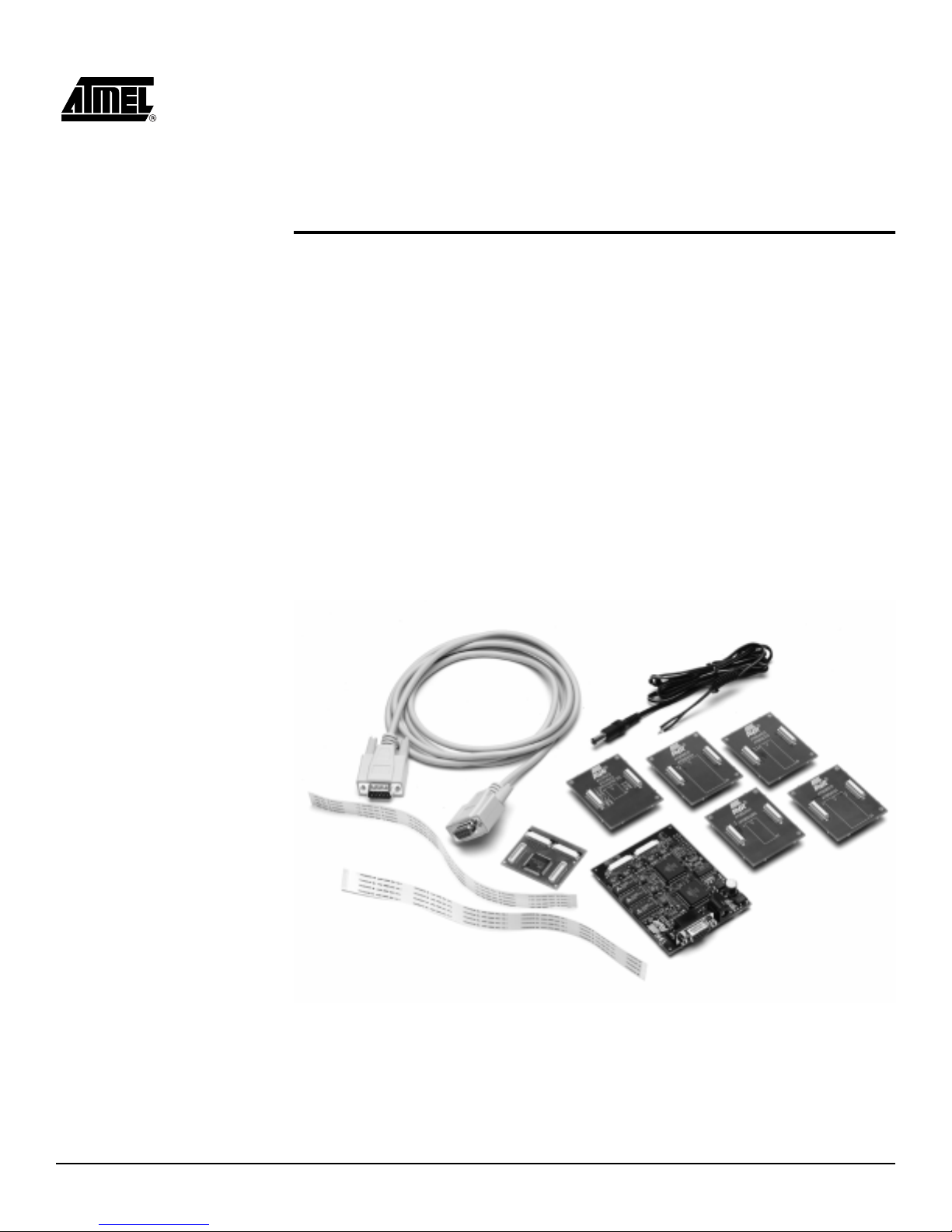
Figure 2-1.
The ICE 200 Components
When used with the AVR Studio debugging environment, the ICE 200 gives the user full
run time control, un limited n umber of break points, symbo lic d ebuggi ng and full memo ry
and register visibility. Multiple ICE 200 emulators can be used by AVR Studio at the
same time, only limited by the number of serial ports available, giving a high degree of
flexibility.
Page 8

Introduction
2-2 AVR ICE 200 User Guide
2.1 ICE 200 Features ■ Devices Supported
ATtiny12, AT90S 2313, AT90S 2333/4433, AT 90S4414/85 15, AT90S4434 /8535,
ATtiny10/11 (using ATtiny12 adapter), AT90S1200 (using AT90S2313 adapter)
■ Supports 8 MHz (+4.0V to +6.0V) AVR Emulator Chip (varies between devices
being emulated)
■ Wide Target Voltage Range (+2.7V to +5.5V)
■ Emulator Chip Provides Excellent AC Characteristics
■ Non-intrusive
■ Target Voltage Sensing Ensures Secure Operation
■ Personality Adapter for Each of the Supported Processors
■ 32-bits Cycle Counter
■ I/O Continues to Operate in Halt State After a Break or Breakpoint
■ Single-stepping or Continuous Timer Operation while Single-stepping Code. Utilizes
the AVR Studio Debugging Environment that adds: Full Run Time Control: run, break,
trace into, step over, step out, run-to-cursor, reset, autostep and multistep
■ Unlimited Number of Breakpoints
■ Symbolic Debugging Support
■ Full Visibility of and Access to register File, SP, PC and Memories
■ Access to all I/O Registers – See Section 5: Special Considerations
■ Auto Log Points – Non-real Time Logging/Watches
2.2 ICE 200 Contents The ICE 200 contains the following items:
■ ICE 200 Main Board, pod and two Flexible Printed Circuit Cables
■ Personality Adapters for:
ATtiny12 (8-pin DIP)
AT90S2313 (20-pin DIP)
AT90S2333/4433 (28-pin DIP)
AT90S4414/8515 (40-pin DIP)
AT90S4434/8535 (40-pin DIP)
■ 9-pin RS232C Cable
■ Atmel CD ROM containing:
AVR data books
Application notes
AVR Studio
AVR Assembler
■ ICE 200 User Guide (this document)
■ Power Cable
■ Diagnostic Adapter for Test Purposes
Page 9

Introduction
AVR ICE 200 User Guide 2-3
2.3 System
Requirements
2.3.1 Hardware
Requirements
Pentium-class personal computer with the following specifications is recommended:
■ 16M Byte RAM, or more
■ 3M Byte of free hard disk space
■ CD-ROM or Internet access (for software and data books)
■ VGA monitor, or better
■ 16650 Compatible Serial Port (COM port)
2.3.2 Software
Requirements
The following operating systems are currently supported by AVR Studio:
■ AVR Studio v2.00 or later installed. See the Atmel web site (www.atmel.com) for
latest version.
■ Microsoft Windows NT 3.51
■ Microsoft Windows NT 4.0
■ Microsoft Windows 95
■ Microsoft Windows 98
Note:
AVR Studio will be updated to execute new versions of these operating
systems. See AVR Studio User Guide for latest information.
2.3.3 Operating
Conditions
■ Operation Temperature: 0
°
C - 70°C
■ Operating Humidity: 10 - 90% RH (non-condensing)
■ Supply Voltage: +9.0V to +12.0V DC or 9.0V AC
■ Supply Current: 400 mA
NOTICE!
Violating the recommended operating conditions for the ICE 200 might
cause incorrect operation and damage the emulator.
2.3.4 Host Interface RS-232C @ 19200 bps, 1 start-, 8 data- and 1 stop-bit, no parity. 9-pin female
connector.
Page 10

Introduction
2-4 AVR ICE 200 User Guide
Page 11
AVR ICE 200 User Guide 3-1
Section 3
General Description
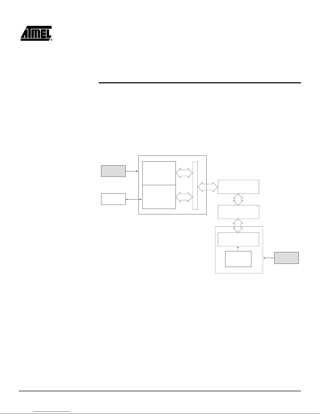
Figure 3-1 shows a simplified block diagram of the ICE 200 connected to a target board
(the application). Power supplies and a host PC are also shown.
Figure 3-1.
ICE 200 – Sim plified Block Diagram
Power
Supply
Host PC
Main Board (5.0V)
Program Memory
Control and
Communication
Logic
Level Converters
POD
(AT90EM04)
Personality
Adapter
Target MCU
Socket
Target Clock
(or XTAL or
Resonator)
Target Board (2.7 - 5.5V)
Power
Supply
FPC
Page 12
General Description
3-2 AVR ICE 200 User Guide
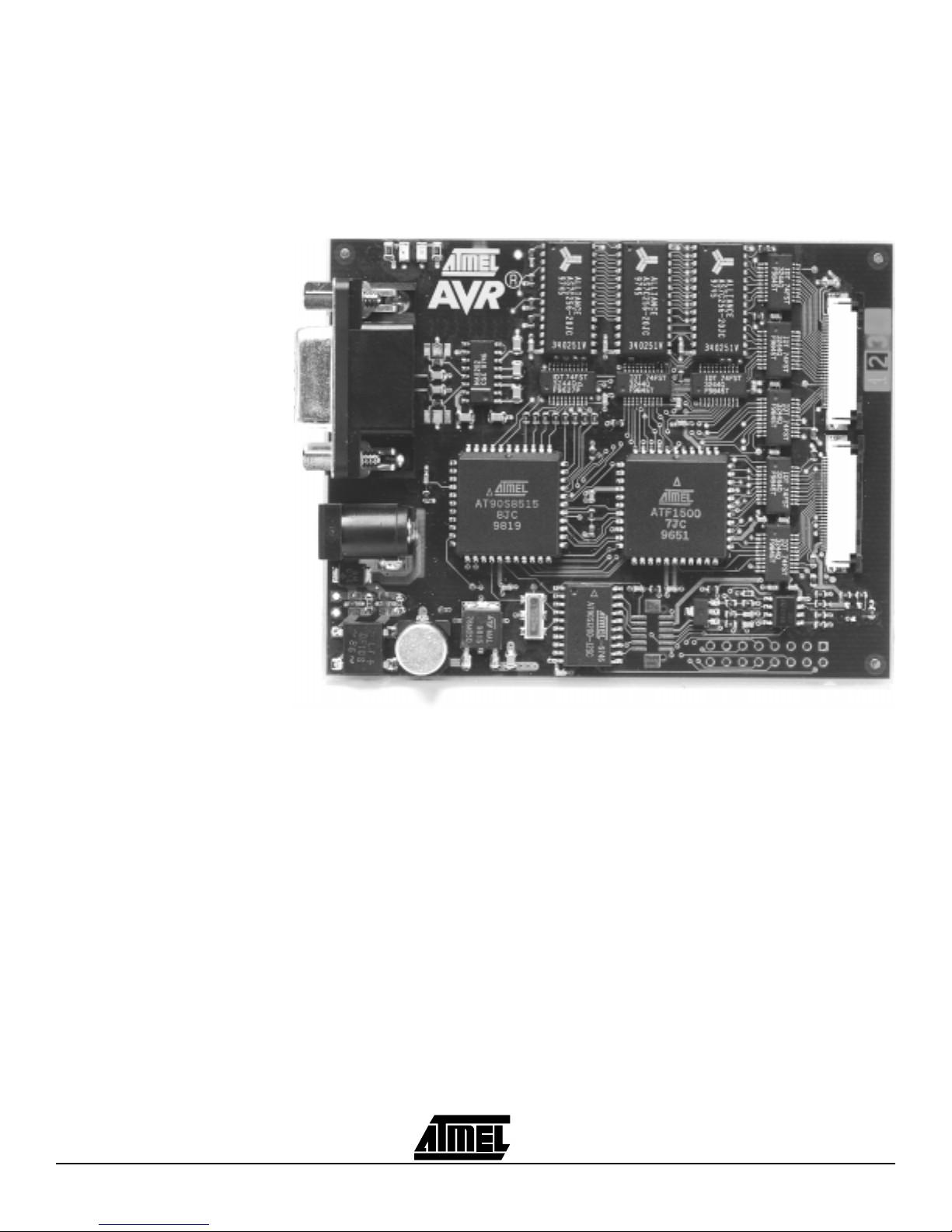
The main board (Figure 3-2) contains the program memory (overlay memory) which
holds the application code that is being emulated. The main board also contains logic for
communicating with the host PC, and the breakpoint lo gic. The level converters allow
the target to operate at a different supply voltage fr om that of the emulator. The level
converters also protect the emulator and the target from being damaged if only one of
them is powered. Due to this feature, a strict power-up sequence is not required.
Figure 3-2.
ICE 200 – Main Board
Page 13

General Description
AVR ICE 200 User Guide 3-3
The FPC or Flexible Printed Cable (Fig ur e 3- 3) co nnec ts the ma in board to the I CE 20 0
Pod. The actual appearance of the FPC may differ from the figure.
Figure 3-3.
ICE 200 – FPC
NOTICE!
The Flexible Printed Cable must not be folded.
NOTICE!
Do not disassemble the Flexible Printed Cable from the pod or ICE 200
main board.
Page 14

General Description
3-4 AVR ICE 200 User Guide
The pod (Figure 3-4) contai ns th e AVR emula tor chi p. Note that th e AVR emula tor c hip
must be supplied with power and a clock source, i.e. a cr ystal, resonator, oscill ator or
any other clock generator, from the target.
Figure 3-4.
The ICE 200 Pod
Page 15

General Description
AVR ICE 200 User Guide 3-5
The personality adapters (Figure 3-5) map the pinout from ICE 200 Pod to each
microcontroller it supports. The a dap ters i nclude an i dentifi cation code that AVR Studi o
uses for automatic device type detection. The ICE 200 kit contains five different
personality adapters for dual-in-line package devices.
Figure 3-5.
The ICE 200 – Personality Adapter for the AT90S8535 – ATadap3100
Page 16

General Description
3-6 AVR ICE 200 User Guide
Page 17

AVR ICE 200 User Guide 4-1
Section 4
Using the ICE 200
Before opening the ESD protection bag, take precaution to eliminate electrostatic discharge. Always use ESD protected tools and clothing when using the ICE 200.
Grounded wrist-band and static-dissipative work surface provides the most effici ent
ESD protection. The ICE 200 should be ha ndled with the same car e as any CM OS
component.
NOTICE!
ESD (Electrostatic Discharge) SENSITIVE DEVICE. Do not use the ICE 200
outside an ESD protected environment.
A discharge may result in permanent damage or performance degradation.
4.1 Target Hardware
Requirements
The target application hardware must include both power supply and a clock source.
The ICE 200 can not function unless these conditions are met. Note that the emulator
also supports the internal RC-oscillator option to the Tiny12 device.
©
Tip!
You can use an AVR development board (ATMCU00100 or ATSTK200) for
using the ICE 200 as a standalone emulator platform.
Please follow the recommended operating conditions listed in the next two sections.
These conditions also apply for the standard AVR microcontrollers.
4.2 Power and
Signal Operating
Conditions
Note:
When VCC < 2.4V, the AVR emulator chip is reset and the program
memory disconnected.
The ICE 200 does not support +12V RESET pin voltage that is used
for parallel programming.
Table 4-1.
Recommended Operating Conditions, Power and Signals (TA = 0°C to 70°C,
V
CC
= +2.7V to +5.5V, GND = 0V)
Symbol Min Max
V
CC
2.7V 5.5V
AV
CC
V
CC
VCC ± 0.3V
AGND GND GND
AREF AGND AV
CC
VSI (Signal Input Voltage) -0.5V VCC + 0.5V
V
RESET
(RESET pin input Voltage) GND V
CC
Page 18

Using the ICE 200
4-2 AVR ICE 200 User Guide
4.3 Clock Driver
Requirements
AVR microcontrollers are fully static designs. The processor clock can be stopped externally. The AVR emulator chip needs a clock to communicate with the main board.
Without a clock source, the host PC gets a serial communication time-out when reading
status or variables from the emulator. Please refer to the datasheet for information about
clock oscillator options.
NOTICE!
Using the ICE 200 outside the recommended operating conditions will
cause incorrect operation and can damage the emulator.
Table 4-2.
Recommended Operati ng Conditions, Clock Drive (+ 4.0V to +5.5V)
(T
A
=0°C to 70°C, VCC = +4.0V to +5.5V, GND = 0V)
Symbol Min Max
f
osc
(ATtiny12) 32.768 kHz 8 MHz
f
osc
(AT90S2313) 32.768 kHz 10 MHz
f
osc
(AT90S4433/2333) 32.768 kHz 10 MHZ
f
osc
(AT90S8515/4414) 32.768 kHz 8 MHz
f
osc
(AT90S8535/4434) 32.768 kHz 8 MHz
Table 4-3.
Recommended Operating Conditions, Clock Drive (Low-voltage +2.7V to
+4.0V) (T
A
= 0°C to 70°C, VCC = +2.7V to +4.0V, GND = 0V)
Symbol Min Max
f
osc
(ATtiny12/) 32.768 kHz 4 MHz
f
osc
(AT90S2313) 32.768 kHz 4 MHz
f
osc
(AT90S4433/2333) 32.768 kHz 4 MHz
f
osc
(AT90S8515/4414) 32.768 kHz 4 MHz
f
osc
(AT90S8535/4434) 32.768 kHz 4 MHz
Page 19

Using the ICE 200
AVR ICE 200 User Guide 4-3
4.4 Personality
Adapters
The ICE 200 is supplied with five different personality adapters. Each adapter makes the
pinout mapping for one or more AVR microcontrollers.
©
Tip!
Mounting a DIP socket on the personality adapter reduces the risk of breaking
pins on the adapter, thus extending adapter lifetime.
©
Tip!
You can mount additional DIP sockets to the adapter to increase the space
between the adapter and the target. However, the number of extra sockets
should be kept at a minimum.
If you are utilizing surface mount device (SMD) versions of the suppor ted AVR microcontrollers, you n eed to obtain an SMD adapter th at converts from DIP to the
appropriate socket.
Figure 4-1.
Personality Adapter for ATtiny12 – ATadap3400
Page 20

Using the ICE 200
4-4 AVR ICE 200 User Guide
Figure 4-2.
Personality Adapter for AT90S2313 – ATadap3300
Figure 4-3.
Personality Adapter for AT90S4433/2333 – ATadap3200
Page 21

Using the ICE 200
AVR ICE 200 User Guide 4-5
Figure 4-4.
Personality Adapter for AT90S8515/4414 – ATadap3000
Figure 4-5.
Personality Adapter for AT90S8535/4434 – ATadap3100
NOTICE!
Do not change personality adapter without turning power-off on both
the emulator and the target.
Page 22

Using the ICE 200
4-6 AVR ICE 200 User Guide
4.5 Special Tiny12
Personality
Adapter Settings
The AVR ATtiny12 microcontroller includes some special oscillator pin features that
could not be implemented in the AVR emulator chip due to its multiple device support.
However, the options are supported on the personality adapter by changing the position
of two zero ohm resistors that configure the port and the oscillator pin mapping. The setting of the resistors is shown in Figure 4-6.
The resistor setting depends o n the des ired cloc k config uration. S elect the resist or
setting based on the table below. Default factory resistor setting is internal RC oscillator.
Figure 4-6.
Settings of Resistors on ATadap3400
The personality adapter board has four additional resistors. These are used as identification codes for the a utomatic c onfiguration an d for produc tion test p urposes. Do n ot
remove these resistors!
XTAL1
XTAL2
XTAL1
PB4 XTAL1 PB4 PB3 PB4
V
CC
System
Clock
I/O I/O I/O I/O
External
Crystal or
Resonator
External RC
Oscillator
External
Clock Source
Internal RC
Oscillator
PB3
PB4
XTAL1
XTAL2
PB3
PB4
XTAL1
XTAL2
PB3
PB4
XTAL1
XTAL2
PB3
PB4
XTAL1
XTAL2
Inside Device
Outside Device
Configuration
Resistor
Setting
System
Clock
System
Clock
System
Clock
Page 23

Using the ICE 200
AVR ICE 200 User Guide 4-7
4.6 Connecting to
the Target
Application
The procedure in this section must be followed when setting-up the emulator. The end
of this section contai ns a usefu l checklist f or ensuring fast and safe installati on of the
system.
1. Before connecting the ICE 200 to the target application, make sure that the ICE
200 and the target application are not powered . This also appl ie s when the ICE
200 is removed from the target. When connecting or disconnecting the ICE 200
from the host PC, make sure that neither the ICE 200 nor the target application is
powered.
2. Start inserting a personality adapter (see Figure 4-7). Make sure that pin 1 on the
personality adapter corresponds with pin 1 on the target socket.
Figure 4-7.
Inserting a Personality Adapter into the Target Hardware
Page 24

Using the ICE 200
4-8 AVR ICE 200 User Guide
3. If the flexible printed circuit cable (FPC) is not already connected to the pod and
the main board, connect it as shown in Figure 4-8. Note that the FPC lead prints
must face up.
Figure 4-8.
Mounting the FPC to the pod and the Main Board
4. Mount the pod onto the personality adapter as shown in Figure 4-9. Do not use
force since the pod only fits one way into the personality adapter.
Figure 4-9.
Mounting the pod onto the Personality Adapter
5. Connect the ICE 200 to the host PC. Use the 9-pin RS232C cable that is shipped
with the ICE 200. Connect the male cable connector to the ICE 200 and the
female cable connector to the host.
Figure 4-10.
Connecting the ICE 200 to a Host PC
Page 25

Using the ICE 200
AVR ICE 200 User Guide 4-9
6. AVR Studio can now be started. However, do not open any files before connecting power supply to the ICE 200. If the ICE 200 is not powered then AVR Studio
cannot detect the emulator and therefore enters simulation mode.
7. The ICE 200 has no power switch. Just connect the power supply cable shipped
with the ICE 200 to a +9V to +12V DC or a 9V AC power supply, and then connect the power cable to the ICE 200 (see Figure 4-11). A battery eliminator is a
good alternative to the laboratory power supply shown on the figure.
Figure 4-11.
Connecting Power Supply to ICE 200
8. Enable the target power supply. The red LED will now be lit, telling that power is
present, but no connection to the host PC has been established.
The hardware is now ready for use. Use the checklist below to ensure that the setup
was done correctly, and then proceed to the next section: Configuration.
4.6.1 Checklist 1.o Turn-off power on all units.
2.o Insert personality adapter.
3.o Pins on adapter agree with pins on target.
4.o Mount pod.
5. o Mount FPC (first time only, do not disassemble).
6. o Connect RS232C cable.
7. o Turn-on power on all units.
Page 26

Using the ICE 200
4-10 AVR ICE 200 User Guide
4.7 Configuration When the ICE 200 is connected to the target applicati on, the next step is to set the
device configuration of the part you are using. This is required when an application code
project is opened for the first time, but can later be changed in the emulator options
menu. The configuration is stored in a separate file, [project name].avd, in the same
directory as the application code.
4.8 Quick Start Follow the procedure described below to configure the ICE 200.
1. Connect the ICE 200 and start AVR Studio as described in previous section.
2. Open the object file. If the file is opened in AVR Studio for the first time, the
Emulator Options Window automatically appears, see Figure 4-12. The red LED
will now be turned off and the green will be turned on (if it is not already on), indicating that the connection between the ICE 200 and the host PC is established.
Figure 4-12.
ICE 200 Configuration Dialog
3. Set up the desired configuration. A detailed description is found in the following
sections, however, the default settings are sufficient in most cases due to the
automatic personality adap ter detec tio n.
4. Press the OK button.
5. The ICE 200 is now ready for use!
© Tip!
To change configuration for the current project, se lect the Option – Emulator
Options menu.
Page 27

Using the ICE 200
AVR ICE 200 User Guide 4-11
For advanced users, Sect ion 4.9 describe s in more detail the poss ible settings in the
Options menu.
The software is now ready for use. Use the checklist below to ensure that the setup was
done correctly. The ICE 200 is now ready for debugging.
©
Tip!
If AVR Studio cannot connect to the emulator, make sure no other programs
are using the serial port.
4.8.1 Checklist 1.o The personality adapter selected corresponds to the device that is to be used.
2.o Target application is correctly connected to the emulator (as described in
previous section).
3.o AVR Studio detects that the emulator is present when opening the
application code.
4.o The Options menu for ICE 200 was shown when opening the source file
(only first time).
5.o The device in the Options menu correspond to the chip configuration you
want to use.
6.o The text “AVR Emulator” appears in the status bar of AVR Studio found in the
lower right corner of the window.
4.9 Emulator
Options Settings
4.9.1 Device Settings Some devices have identical pinout and functionality. An example is the AT90S8515
and the AT90S4414 devices, there is no need for a personality adapter for each of them.
The automatic pers onal ity adap ter detect ion ens ures c orrec t pi nout con fig uration of th e
AVR emulator chip. When se lectin g a specif ic devic e enter, the emulator options menu
and select the device from the device list.
4.9.2 Clock Selection
Settings
Many AVR microcontrollers have fuse bits for selecting the reset delay time. The reset
delay is necessary fo r the clock osci llator t o stab ilize. Th e time it tak es for t he osc illator
to stabilize depend s on th e crysta l or th e reson ator. If an ext ernal c lock s ource i s used
then the reset delay can be set to only a few clocks. The reset delay fuse bits
(CKSEL/FSTRT depending on device) can be set or cleared by a parallel or serial programmer in an actual device. In the emulator, they are set in the options menu.
For more information about the reset delay fuses, please refer to the datasheets.
4.9.3 Single-step Timers
Setting
This setting allo ws sin gle-steppi ng of th e timer s if che cked. If cleared the timer s continue to count ( if en abled ) eve n afte r the p rogr am e xecuti on i s stopp ed by a user b reak
or breakpoint. All other peripherals (SPI/UART/EEPROM/PORTs) continue to operate
when the program execution is stopped.
This feature allows cycle-by -cycle debug ging of th e counter value, whi ch is use ful for
event timing. However , in many case s, stopping the counter ope ration whi le debuggin g
might not be desired. One example is when the timer is used in PWM mode. Stopping
the timer in this case might da mage the equipment t hat is b eing c ontrolle d by the PW M
output.
Note that eventual timer interrupts will not be handled before execution is resumed.
Page 28

Using the ICE 200
4-12 AVR ICE 200 User Guide
4.9.4 EEPROM Restore
Setting
Some AVR devices have o n-chip EEP ROM d ata memory . The ICE 2 00 emula tes the
EEPROM by using an SRAM replacement inside the AVR emulator chip. This is done to
eliminate problems with EE PROM wri te endu rance. How ever , by doi ng so, a new problem is introduced si nc e a po wer los s on the target will result in l oss of th e da ta st or ed i n
the SRAM that emulates the EEPROM.
A split solution handles the power loss situation. First select the EEPROM restore
option. Before removing the power, take a snapshot of the EEPROM contents by pressing the EEPROM snapshot button (Figure 4-13). This will tell the ICE 200 main board to
read all EEPROM data into a buffer . W hen po wer is swi tch ed off and then on aga in, the
ICE 200 will restore the contents of the buffer to the SRAM before starting code
execution.
Figure 4-13.
EEPROM Snapshot Button
4.9.5 Communication
Speed Setting
The default communication speed between AVR Studio and the ICE 200 is 19200 bps. If
the option “115200 bps Communic ation” is selected, the co mmunication speed is
changed to 115200 bps. Some systems cannot handle this speed, so if AVR Studio
looses contact with the emulator after enabling this option, it should be disabled.
4.9.6 Reset Pin Setting
(ATtiny12 only)
When selecting ATtin y12 an addit ional option se lecti on appea rs in the emula tor opti ons
dialog box. The ATtiny12 device has a programmable fuse that lets the RESET pin function as an input pin (PB5). When this option is selected, PB5 functions as a normal reset
pin. When this option is no t selecte d, PB5 functi ons as an in put pin. The de vice is the n
only reset at power-on or when giving a reset command from AVR Studio. Refer to the
ATtiny12 datasheet for more information.
Page 29

AVR ICE 200 User Guide 5-1
Section 5
Special Considerations
The ICE 200 accurately emulates most AVR features. However, there are some differences worth n oting. Most of the exce ptions a pply to contr olling the progra m flow, i.e.
single-stepping and so on. Prog ram fl ow control is an exte nsion to the nor mal functi ons
of the microcontroller that al lows the user to do the de buggin g. This ex tension mu st not
interfere with the normal program execution (run mode). If the program execution is
stopped (stopped mode) and then restarted, or the program is executed line-by-line
(single-stepping), the program functionality can, in some cases, be affected.
5.1 External RESET The ICE 200 main board has to be able to control the reset pin on the AVR emulator
chip. An external r eset source must therefore go via the c ontrol logic as sho wn
on Figure 5-1. This is handled automatically by the pod and main board
Figure 5-1.
ICE 200, External RESET Circuit
The main board is working with 5V supp ly and the pod uses the target voltage.
Therefore, a level converter is inserted between the two sy stems. The extra lo gic and
the level converters introduce a small, and for most of the time, negligible delay. Note
that the voltage converters do not handle a +12V input voltage on the RESET pin which
is used for enabling the parallel programming on standard parts.
After a power-up, the reset is forced active while configuring the AVR emulator chip,
introducing a 1 - 10 ms delay.
PODMAIN BOARD
Voltage Level Converter
FORCE RESET
ENABLE RESET
RESET
External RESET
Page 30

Special Considerations
5-2 AVR ICE 200 User Guide
5.2 SLEEP
Instruction
If a SLEEP instruction is executed and sleep is enabled the AVR emulator chip will enter
one of the AVR low-powe r modes (power-down, po wer-save o r idle). The power consumption will be slightly higher compared to the real chip due to the higher complexity of
the emulator chip. In room temperature (25°C) this is not significant.
©
Tip!
When debugging your application, you can replace the SLEEP instruction
with a NOP by using macros.
IAR C example:
#ifdef SLEEPEMU
#define SLEEP() _SLEEP()
#else
#define SLEEP() _NOP()
#endif
5.3 Watchdog Timer
(WDT)
The watchdog timer operates asynchronously (it has its own clock) to the rest of the
system. The watchdog timer reset instruction is therefore repeatedly issued in stopped
mode to avoid false resets if the watchdog timer is enabled. Debugging the exact timing
of the WDT behavior whil e doing sing le-ste pping or when stoppin g the progra m execution, is therefore not supported by the ICE 200.
Disabling WDT is secured by the W DTTOE (WDT turn-off enable) bit. F ollowing is an
assembly program example that shows a WDT disable sequence:
disableWDT:
( cli ) ; (only needed if any interrupts are in
; use)
ldi r16, (1<<WDTTOE)+(1<<WDE) ; Set the WDT turn-off enable bit and
; the WDE bit
out WDTCR, r16
ldi r16, (0<<WDE) ; Within 4 cycles, clear the WDEbit
out WDTCR, r16
done:
( sei ) ; (only needed if any interrupts are in use)
The four cycle time-out for the WDT disabling is not supported by the AVR emulator chip
when in stopped mode. This means that single-stepping this sequence will not disable
the WDT.
©
Tip!
You can use the run to cursor to the instruction after the WDT enable bit is
cleared (labelled done in the ex ample above), inst ead of doing single -stepping. Or use the following macro (for AVR assembler only).
MACRO:
.macro disableWDT
( cli )
ldi r16, (1<<WDTTOE)+(1<<WDE)
out WDTCR, r16
ldi r16, (0<<WDE)
out WDTCR, r16
( sei )
.endmacro
USAGE:
disableWDT
Page 31

Special Considerations
AVR ICE 200 User Guide 5-3
5.4 EEPROM When writing to the on-board EEPROM on an AVR device, a special sequence must be
used to ensure the integrity of the EEPROM data. Following is an ass embly progra m
example that shows an EEPROM write sequence:
writeEEPROM:
( cli ) ; (only needed if any interrupts are in use)
sbi EECR, EEMWE
sbi EECR, EEWE
done:
( sei ) ; (only needed if any interrupts are in use)
The four cycle ti me-out for the EEPROM write is n ot supporte d by the AVR emulator
chip when in stopped mode. T his means that si ngle-stepping this s equence will not
strobe an EEPROM write.
©
Tip!
You can use the run to cursor to the instructio n after the EEP ROM write
enable bit is set (labeled done in the exa mple above) , i nstead of doing singlestepping. Or use the macro defined below.
MACRO:
.macro writeEEPROM
( cli )
sbi EECR, EEMWE
sbi EECR, EEWE
( sei )
.endmacro
USAGE:
writeEEPROM
5.5 I/O Port Access A special situa tio n occu rs wh en si ngle- step ping a cha nge of the P ORT v alue as show n
in the following example:
write_with_readback:
ldi r16, 0xFF ; Set all pins as output
out DDRx,r16 ; -"out PORTx, r16 ; Set the PORTx values
in r16,PINx ; Read the PINx values
in r17,PINx ; Read the PINx values
When running this example program at full-speed in the ICE 200 or in a real chip , the
value read back in r16 will not end up being the value written at the first line, but will
contain the value the port pins had the cycle before the port was written. This is the
correct beha vi or . The P INx value must be sync hr oni ze d, a nd t her efo r e it is de la ye d one
cycle to avoid erratic port behavior caused by metastability. r17 will therefore contain the
value written to the port. However, when the program is single-stepped, the value of the
PINx will change immediately after the single-step and the value of r16 will contain the
same value as before.
Changing pin values on an I/O port from AVR Studio when the ICE 200 emulator is
stopped does not represent any problem. However, note that, as for the single-stepping
case, the pin values are changed immediately.
Clearly this is not a real problem, but it is important to be aware of the effects of the two
cases described above. If not, an incorrect program might seem to work in the emulator,
but will not work in the real chip.
Page 32

Special Considerations
5-4 AVR ICE 200 User Guide
5.6 16-bit I/O Access
(Timer 1 and A/D
Converter)
Reading or writing 16-bit values directly from AVR Studio can cause some problems. To
read, for example the counter value from timer 1, a 16-bit value, one of the bytes must
be stored in a temporary register. This temporary register will be corrupted if the 16-bit
value is read when the program execution is stopped.
©
Tip!
Using the following macros (for AVR assembler only) will solve the 16-bit
access problem when using symbolic debugging.
MACROS:
.macro outw
(cli)
out @2, @0
out @2-1, @1
(sei)
.endmacro
.macro inw
(cli)
in @2, @0-1
in @1, @0
(sei)
.endmacro
USAGE:
inw r17, r16, TCNT1H ; Reads the counter value
outw TCNT1H, r17, r16 ; Writes the counter value
When using symbol ic debug gin g in C, the entir e C li ne is ex ecuted for eac h set. Ther efore the 16-bit read or write problem will not occur in this situation.
5.7 UART Data
Register
Reading the UART Data Register cleans the RXC bit in the UART Control Register.
Hence, the monitor program does not attempt to read the UART Data Register. Therefore, the value displayed by AVR Studio for this register does not reflect the real value of
this register.
Page 33

AVR ICE 200 User Guide 6-1
Section 6
Appendix
6.1 Emulating
AT90S1200 and
ATtiny10/11
6.1.1 Using the Include
Files
Always use incl ude files fo r the I/O reg isters ad dresses and for bit definition s in your
source code fil es . This will eas e t he process of portin g code from one microcontr ol le r t o
another. The fil es can b e found on the CD-ROM which is i ncluded in the ICE 200 kit.
Copy the include file to your project director y, and includ e it in the top of the pro gram
code as shown below:
(AVR Assembler example)
.include "1200def.inc"
Then, when writing a value to a I/O register, use the following notation:
(AVR Assembler example)
ldi r16, (1<<DDD1) + (1<<DDD4) ; Set port D pin 1 and 4 as output and
; the rest as input.
out DDRD, r16
Note the use of the bit definitions. DDD1 and DDD4 are pin definitions in form of bit
position, and therefore they must be shifted this number of bits to the left to make a
correct mask.
Interrupt vector locations might differ from part-to-part. This is easily handled by using
the vector definitions found in the include files.
(AVR Assembler example)
.include "1200def.inc"
.org 0
rjmp RESET_Handler
.org INT0addr
rjmp INT0_Handler
.org OVF0addr
rjmp OVF0_Handler
.org ACIaddr
rjmp ACI_Handler
... ( program code starts here )
Page 34

Appendix
6-2 AVR ICE 200 User Guide
6.1.2 Using the ATtiny12
Adapter for
Emulating the
ATtiny10/11
The ATtiny10 and 11 are both subsets of ATtiny12. Therefore, it is possible to select the
ATtiny12 device when configuring the ICE 200 to support either ATtiny10 or ATtiny11.
These devices all have the same pinout, b ut ATtiny10 /11 does not have th e following
features:
•
Brown Out Detection (BOD)
• Calibration of the RC Oscillator
• Reset Source Register
• Band-gap Reference on the Comparator
• EEPROM Interrupt
Also note that the startup times differ slightly between the devices. Please refer to the
datasheets for more detailed information.
6.1.3 Using the
AT90S2313 Adapter
for Emulating the
AT90S1200
The AT90S1200 can be defined as a subset of AT90S2313. They have the same pinout,
but AT90S1200 does not have the following features:
•
UART
• SRAM
• Memory Access Instructions (ld/st/lds/sts/ldd/std/lpm)
• 16-bit Arithmetic Instructions (adiw/sbiw)
• INT1
• Timer/Counter 1 and Input Capture
• Stack Pointer to SRAM (AT90S1200 has a 3 level hardware stack)
Avoiding the use of these features and using only half the program and EEPROM
memories allows the AT90S2313 to be used when emulating AT90S1200.
IMPORTANT!
Since the AT90S2313 uses a stack pointer, this has to be initialized. The simplest way is
include the following lines at the top of the program code:
( AVR Assembler example )
ldi r16, 0x65 ; Set the stack pointer to point at the address to
; give a 3-level deep stack
out 0x3D, r16
The AT90S2313 has no RC oscill ator, so this fea ture found on the AT90 S1200 can not
be supported.
Since the AT90S2313 features the EEMWE bit for writing data to the EEPROM memory,
this must also be added to the AT90S1200 code if the EEPROM is used.
Include the AT90 S2313 file when emulati ng AT9 0S120 0 to g et the inte rrupts plac ed o n
the right locations, see Section 6.1.1.
6.2 AVR Emulator
Chip Errata
Latest errata is found on the Atmel web site: www.atmel.com.
Page 35

Appendix
AVR ICE 200 User Guide 6-3
6.3 Troubleshooting If you experience prob lems when installing AVR Studio, connecting the em ulator or
configuring the emulator, first of all use the checklists in the previous sections to confirm
that you have done installation and the setup of the emulator correctly.
6.3.1 Feedback and
Support
To get correct answers to your problems, please include the following details in
your reques t.
ICE 200/AVR Studio:
■ Details of which release of ICE 200 you are using
■ Details of the platform on which you are running (OS, amount of memory, etc.)
■ A small stand-alone sample of code which reproduces the problem
■ A clear explanation of what you expected to happen, and what actually happened
■ The commands or menu selections you used
■ Sample output illustrating the problem
■ The information shown in the About dialog box in AVR Studio (version numbers)
■ The emulated device
Documentation:
■ The manual title and revision
■ The page number(s)
■ A concise explanation of the problem
General suggestions for additions and improvements are also welcome
6.4 Contact
Information
For technical support, please contact your distributor, Atmel sales representative or
local Atmel sales office. Atmel s ales offices and distributor s are listed in the AVR
Databook and on the Atmel web site: www.atmel.com.
Page 36

Appendix
6-4 AVR ICE 200 User Guide
Page 37

Appendix
AVR ICE 200 User Guide 6-5
Page 38

Appendix
6-6 AVR ICE 200 User Guide
Page 39

Page 40

© Atmel Corporation 1999.
Atmel Corporation makes no warranty for the use of its products, other than those expressly contained in the Company’s standard warranty which is detailed in Atmel’s Terms and Conditions located on the Company’s web site. The Company assumes no responsibility for
any errors which may appear in this document, reserves the right to change devices or specifications detailed herein at any time without
notice, and does not make any commitment to update the information contained herein. No licenses to patents or other intellectual property of Atmel are granted by the Company in connection with the sale of Atmel products, expressly or by implication. Atmel’s products are
not authorized for use as critical components in life support devices or systems.
Atmel Headquarters Atmel Operations
Corporate Headquarters
2325 Orchard Parkway
San Jose, CA 95131
TEL (408) 441- 0311
FAX (408) 487-2600
Europe
Atmel U.K., Ltd.
Coliseum Business Centre
Riverside Way
Camberley, Surrey GU15 3YL
England
TEL (44) 1276-686-677
FAX (44) 1276-686-697
Asia
Atmel Asia, Ltd.
Room 1219
Chinachem Golden Plaza
77 Mody Road Tsimhatsui
East Kowloon
Hong Kong
TEL (852) 2721 -9778
FAX (852) 2722-1369
Japan
Atmel Japan K.K.
9F, Tonetsu Shinkawa Bldg.
1-24-8 Shink awa
Chuo-ku, Tokyo 104-0033
Japan
TEL (81) 3-3523-3551
FAX (81) 3-3523-7581
Atmel Colorado Springs
1150 E. Cheyenne Mtn. Blvd.
Colorado Springs, CO 80906
TEL (719) 576-3300
FAX (719) 540-1759
Atmel Rousset
Zone Indu strie lle
13106 Rousset Cedex
France
TEL (33) 4-4253-6000
FAX (33) 4-4253-6001
Fax-on-Demand
North America:
1-(800) 292-8635
International:
1-(408) 441-0732
e-mail
literature@atmel.com
Web Site
http://www.atmel.com
BBS
1-(408) 436-4309
Printed on recycled paper.
1413A–07/99/5M
Microsoft, Windows and Windows NT are trademarks of Microsoft Corporation. Pentium is a trademark
of Intel Corporation. Acrobat Reader is trademark of Adobe Systems Incorporated.
All other marks bearing
®
and/or ™ are registered trademarks and trademarks of Atmel Corporation.
Terms and product names in this document may be trademarks of others.
 Loading...