

Page 1
PLUS MAKE YOUR PRODUCTION A-PLUS
A
AVxx08 Series
DATA SHEET
PLUS INTEGRATED CIRCUITS INC.
A
Address:
3 F-10, No. 32, Sec. 1, Chenggung Rd., Taipei,
Taiwan 115, R.O.C.
(115)台北市南港區成功路㆒段 32 號 3 樓之 10.
TEL: 886-2-2782-9266
FAX: 886-2-2782-9255
WEBSITE : http: //www.aplusinc.com.tw
Sales E-mail:
sales@aplusinc.com.tw
Technology E-mail:
service@aplusinc.com.tw
Page 2
AVxx08 Series
1. GENERAL DESCRIPTION:
The AVH308 , AV0708 , AV1408 and AV2108 are single-chip voice synthesizing CMOS IC.
They are low cost with proper functions and can synthesize voice up to 3.5, 7, 14 and 21 seconds, using
Aplus 4-bit LOGPCM algorithm. Customer speech data can be programmed into ROM by changing one mask
during the device fabrication. Besides, not only a very flexi ble functions I/O pin is available for the user to
apply in various applications, but also an interactive development tool “EzSpeech” is ready for user-friendly
programming.
2. FEATURES:
(1). Single power supply can operate from 2.4V to 6.4V (in this range, user can set Rosc as a fixed value).
(2). The total voice duration is about 3.5, 7, 14 or 21 seconds those can be partitioned up to 8 voice_sections.
Each voice_section length is flexible.
(3). Voice length can be individually up to 3.5, 7, 14 or 21 seconds at 6kHz S.R. for each voice_section.
Voice+mute length can be individually up to 11, 21, 21 or 21 seconds at 6kHz sample rate for each
voice_section.
(4). Total 16 voice_steps are available for 2 sub_tables. Each sub_table can only use maximum 8
voice_steps. For each voice_step, it can specify one voice_section and IO1 output enable options if IO1
is set as an output.
(5). Build in oscillator, 15 kinds of playback speed option for internal resistor used : ( 4.0k ~ 18.1kHz)
A B C D E F G H
18.1kHz 14.4kHz 12.0kHz 10.3kHz 9.0kHz 8.0kHz 7.2kHz 6.6kHz
I J K L M N O -
6.0kHz 5.6kHz 5.2kHz 4.8kHz 4.5kHz 4.3kHz 4.0kHz -
<Internal oscillator: OSC pad must be bonded to GND>
(6). IO1 can be either input or output pin (Mask option).
(7). Optional “Two Triggers Input” (TG and IO1), or “One Trigger Input” (TG pin only).
(A). Each input pin has mask options for Edge/Level, Hold/Unhold and Retrigger/Irritrigger trigger modes.
(B). TG input can choose CDS+1M、CDS、1M pull-low、10M pull low or floating input type.
(C). IO1 input can choose CDS+1M、CDS、1M pull-low or floating input type.
(D). Debounce time: Long debounce for push buttons. Short debounce for switches. (
Input Mode, only one kind of debounce time is available.)
(E). Priority:TG > IO1.
(8). IO1 has the following output option A~F :
(A). Stop_High pulse : high active stop pulse output whenever device stop playing.
(B). Busy_High active : high active signal output during playing.
※
In Two Triggers
Rev 1.3 2003/9/18 1
Page 3
AVxx08 Series
(C). Busy_Low active : low active signal output during playing.
(D). LED 3Hz flash : 3Hz sink signal output for driving LED during playing at 6kHz sample rate.
(E). LED 6Hz flash : 6Hz sink signal output for driving LED during playing at 6kHz sample rate.
(F). LED dynamic 2/4 : dynamic sink signal output for driving LED during playing.
※
Where (D) and (E) is the LED flash rate at 6kHz sample rate. For different sample rate, the LED flash
rate is different from original 3Hz or 6Hz.
(9). PWM1 and PWM2 can directly drive buzzer or 8, 16, 32 or 64 ohms speaker.
(10). The voice_section length of “voice length + mute length” must be the multiple of 80Hex (AVH308 ) or
100Hex (AV0708 , AV1408 , AV2108
).
(11). In voice_section sequence arrangement (00~07), If there are some voice_sections with only mute and
without voice, they should be put next to the last voice_section with voice. Besides, that is not allowed to
put a pure mute voice_section between 2 voice_sections with voice, or put the pure mute voice_section
on first place (00).
(12). Oscillator selection:
(A). External oscillator: Connect OSC pin to Vdd with a resistor, Rosc.
(B). Internal oscillator: Connect OSC pin to GND. (Not suggested because of frequency shift and system
stability)
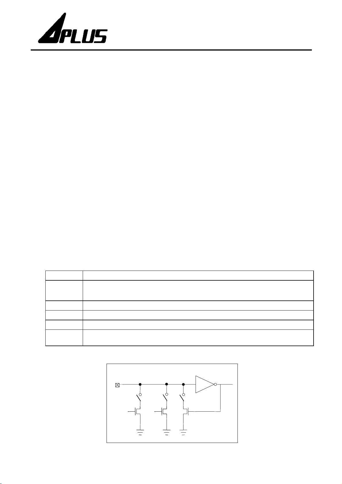
※Input Type Description:
Option Description
Normal selection for button trigger.
CDS + 1M
Only 1M pull-low resistance when key-pressed, and 1M+300K(parallel) pull-low resistance
when key-released.
CDS Internal 300K ohms pull-low resistance, usually for photo-resistor trigger.
1M pull-low Internal 1M ohms pull-low resistance, reserve for some special applications.
10M pull-low Internal 10M ohms weak pull-low, usually for touching trigger.
Floating
No internal resistor connection, usually connected to other output pin or connected to GND
by an external resistor.
* 10M pull-low option is not available for IO1 input.
Trigger
Trigger
PAD
PAD
10M
10M
Pull-Low
Pull-Low
1M
1M
Pull-Low
Pull-Low
Buffer
Buffer
300K
300K
Latch
Latch
Rev 1.3 2003/9/18 2
Page 4

AVxx08 Series
1. ㆒般規格
㆒般規格:
㆒般規格㆒般規格
AVH308 、AV0708 、AV1408 、AV2108 ,皆為單晶片 CMOS 語音合成 IC,他們都是非常
,同時具有相當實用功能的語音 IC 產品。他們以 4-bit LOGPCM 編碼方式,合成長達 3.5、7、14、21
低成本
秒之語音。藉由製造過程㆗更換光罩,將客戶需要之語音資料編寫入ROM㆗。另外使用者可以有㆒個很彈性的
IO pin 選擇 (IO1)
2. 特性
特性:
特性特性
(1). 單㆒工作電壓範圍為 2.4 ~ 6.4 伏特(在此範圍內,可採用單㆒ Rosc 電阻值)。
(2). 語音總長度可達 3.5、7、14、21 秒,且可被分割成8個語音段(voice_section),每段長度可不同。
(3). 每㆒段語音的長度分別最多可達 3.5、7、14、21 秒。(在6kHz取樣頻率㆘)
每㆒段 “語音+靜音時間” 的長度,分別最多可達 11、21、21、21 秒。(在6kHz取樣頻率㆘)
(4). 共有16個語音格(voice_step),可規劃成2個語音組(sub_table),每個語音組最多可放8個語音格。每㆒語
音格可指定㆒語音段並搭配 IO1 輸出致能或非致能(IO1當作輸出時)。
(5). 內建頻率振盪器,共有15種不同播放速度的選擇( p la yb ac k s pee d : 4. 0k ~ 1 8.1kHz):
A B C D E F G H
18.1kHz 14.4kHz 12.0kHz 10.3kHz 9.0kHz 8.0kHz 7.2kHz 6.6kHz
I J K L M N O -
6.0kHz 5.6kHz 5.2kHz 4.8kHz 4.5kHz 4.3kHz 4.0kHz -
<如果選擇內建的頻率振盪器,請將 OSC 腳接㆞。>
,來配合不同之應用,並可用佑華所提供的
EzSpeech
工具軟體來進行開發。
(6). IO1可選擇作輸入腳或是輸出腳 (光罩選擇)。
(7). 可選擇 “兩鍵觸發輸入模式”(TG和IO1) 或 “單鍵TG觸發輸入模式”(IO1當作輸出時)。
(A). 每㆒種輸入可選擇不同觸發方式 (光罩選擇):
邊緣觸發
後段蓋前段 / 非後段蓋前段(Retrigger/Irretrigger)。
(B). TG 輸入可選擇 CDS+1M、CDS、1M pull-low、10M weak-pull lo w 或 floating 的輸入方式。
(C). IO1
(D). 防止誤動作(Debounce)時間:Long - 提供㆒般手動操作;Short - 提供跳動開關使用。
(※ 在”兩鍵觸發輸入模式” 只能選用㆒種
優先順序:
(E).
(8). IO1可做以㆘ 6 種輸出選擇:
(A). Stop_High pulse : 停止播放時送出高位準脈衝。
(B). Busy_High active : 播放時送出高位準訊號。
(C). Busy_Low active :
(D). LED 3Hz flash : 播放時 LED 3Hz 閃爍。(當播放速度為 6kHz 時)
位準觸發
/
輸入可選擇
TG>IO1。
(Edge/Level) ; 保持 /
CDS+1M、CDS、1M pull-low 或 floating
播放時送出低位準訊號。
非保持
(Hold/Unhold) ;
Debounce
時間。
的輸入方式。
)
Rev 1.3 2003/9/18 3
Page 5

(E). LED 6Hz flash :
播放時
LED 6Hz
閃爍。(當播放速度為
(F). LED dynamic 2/4 : 播放時 LED動態 2/4位準訊號。
AVxx08 Series
6kHz 時)
(※
LED 3Hz / 6Hz flash
閃爍的頻率也會不同。
LED
(9). PWM1,PWM2
可直接驅動
是指以
的播放速度 時,
6kHz
閃爍的頻率;不同的播放速度,
LED
)
buzzer 或 8、16、32、64Ω speaker。
(10). 每㆒段語音加㆖靜音的語音段長度會是 80 HEX (AVH308) 、或 100 HEX ( AV0708, AV1408, AV2108 )
的整數倍。
(11). 在語音段的排列順序㆖(00~07),如果遇到有純粹靜音的語音段
(不佔 ROM 空間),㆒定要把它放在有語音
的語音段之後,也不可以將它放在兩個有語音的語音段之間 或 放在第㆒段(00)。
選擇頻率振盪器:
(12).
(A). 選擇外部電阻可調式頻率振盪器 : 將 OSC 外接電阻到正電源。
(B). 選擇內建頻率振盪器 : 將 OSC 接㆞。(
因為頻飄及系統穩定問題,不建議使用
)
※
※ 輸入方式選項
輸入方式選項:
※※
輸入方式選項輸入方式選項
選
選 項項項項 功功功功 能能能能 描描描描 述述述述
選選
㆒般選項,大多用在按鍵觸發。
CDS + 1M
當按鍵按㆘時,IC內部為
的㆘拉電阻。
的㆘拉電阻;而當按鍵放開時,IC內部為
1M
1M+300K (並聯)
CDS
1M pull-low
10M pull-low
Floating
當輸入時,沒有
*IO1
IC內部為 300K 的㆘拉電阻,通常與光敏電阻㆒起使用。
IC內部為 1M 的㆘拉電阻,保留給㆒些特殊應用使用。
內部為
IC
的㆘拉電阻,通常使用在觸控的應用。
10M
IC內部無㆘拉電阻,通常連接到其他輸出腳來做控制使用;如果沒連接其他輸出腳,㆒
定要將此腳位外拉電阻到㆞。
10M pull-low
Trigger
Trigger
PAD
PAD
10M
10M
Pull-Low
Pull-Low
的選項。
1M
1M
Pull-Low
Pull-Low
Buffer
Buffer
300K
300K
Latch
Latch
Rev 1.3 2003/9/18 4
Page 6

3. BLOCK DIAGRAM:
TG
TG
IO1
IO1
C
C
O
O
N
N
T
T
R
R
O
O
O
O
G
G
C
C
AVxx08 Series
4-bit LOG_PCM
4-bit LOG_PCM
DECODER
DECODER
OUTPUT
L
L
L
L
I
I
VOICE
VOICE
ROM
ROM
OUTPUT
BUFFER
BUFFER
CLOCK
OSC
OSC
CLOCK
GENETATOR
GENETATOR
TIMING
TIMING
GENERATOR
GENERATOR
P
P
P
P
W
W
W
W
M
M
M
M
1
2
1
2
4. PAD DESCRIPTION:
Pad Name Pad No. ATTR. Function
IO1 1 I/O Status ou t p ut or in pu t f o r trig ger.
TG 2 I Input for trigger.
GND1, 2 3, 7 Power Negative power supply.
PWM1 4 O Audio output.
Vdd 5 Power Positive power supply.
PWM2 6 O Audio output.
OSC 8 I Oscillator input. For using internal oscillator, connect OSC to GND.
5. CODE DEVELOPMENT & DEMO SYSTEM:
User can use “EzSpeech“ software tool t o develop the desired functions. For details, please see EzSpeech
user manual. After finishing the code programming, user will get 2 files of “.bin” and “.htm”, the binary fil e
and function check list. User can download the “.bin” file into 4EA_DB demo board to demonstrate the
AVxx08 function. The related mapping of 4EA_DB is as below,
AVxx08 4EA_DB 4EA_DB Description
TG PRA0 PRA0 performs TG input.
IO1 as Input PRA1 PRA1 performs IO1 input mode.
I/O Pin
IO1 as Output PRB0 PRB0 performs IO1 output mode.
PW M 1, PWM 2 PWM 1 , PWM2 PW M o u tput t o d ire c tly d r ive s p eake r.
OSC OSC1 OSC1 connect 150K ohms resistor to Vdd.
For some input type option, user may need to connect an external resistor. Please refer to the table below,
AVxx08 4EA_DB 4EA_DB Description
CDS + 1M CDS + 1M The same.
Input
Type
CDS CDS + 1M Al most the same.
1M pull-low Floating Need to connect 1M external resistor to GND.
10M pull-low Floating Need to connect 10M external resistor to GND.
Floating Floating The same.
Once the function has been approved, user only need to send the “.bin” file to Aplus for code tape-out.
Rev 1.3 2003/9/18 5
Page 7

AVxx08 Series
6. ABSOLUTE MAXIMUM RATING:
Symbol Rating Unit
Vdd~Vss -0.5 ~ +7.0 V
Vin Vss -0.3 < Vin < Vdd+0.3 V
Vout GND < Vout < Vdd V
Top (operating) 0 ~ +70 ºC
Tst (storage) -25 ~ +85 ºC
7. DC CHARACTERISTICS:
Symbol Parameter Min. Typ. Max. Unit Condition
Vdd
Operating voltage 2.4 3.0 6.4 V
Isb
Standby 1
Supply current
Iop
Iih
Iil
Iih
Iil
Iih
Iil
Input current: TG, IO1
( 1M pull low )
Input current: TG
( 10M pull low )
Input current: TG & IO1
(CDS)
Operating 200
Ioh
PWM1, PWM2 output current
Iol
Ioh
IO1 output current
Iol
dF/F
dF/F
Frequency stability -5 5 %
Fosc lot variation -10 10 %
8. Frequency vs. External Rosc :
25
25
uA
3
uA Vdd=3V
Vdd=3V, I/O open
(with Rosc or OSC grounded)
0
0.3
uA Vdd=3V
0
10
uA Vdd=3V
0
-30 Vdd=3V, Vop=2.4V
mA
30
Vdd=3V, Vop=0.6V
-4.5 Vdd=3V, Vop=2.55V
mA
7.5
Vdd=3V, Vop=0.75V
Fosc(3v)-Fosc(2.4v)
Fosc(3v)
Vdd=3V, Rosc=220KΩ
20
20
Freq. (K Hz)
Freq. (K Hz)
15
15
10
10
5
5
0
0
50 100 150 200 250 300 350 400
50 100 150 200 250 300 350 400
Rosc (K Ohm)
Rosc (K Ohm)
Rev 1.3 2003/9/18 6
Page 8

9. TIMING DIAGRAM:
1.> Edge/Level
1.> Edge/Level
Edge Mode:
Edge Mode:
Edge Trigger
Edge Trigger
TG1/SC
TG1/SC
AUDIO
AUDIO
Tw
Tw
Sub_table N
Sub_table N
AVxx08 Series
Level Trigger
Level Trigger
Level Mode:
Level Mode:
Edge Trigger
Edge Trigger
Level Trigger
Level Trigger
2.> Hold/Unhold
2.> Hold/Unhold
Hold:
Hold:
Unhold:
Unhold:
Tw
Tw
TG1/SC
TG1/SC
Tw
Tw
Sub_table N
Sub_table N
Sub_table N
Sub_table N
Sub_table N
Sub_table N
Sub_table N
Sub_table N
Sub_table N
Sub_table N
Tw
Tw
Sub_table N
Sub_table N
AUDIO
AUDIO
TG1
TG1
AUDIO
AUDIO
TG1
TG1
AUDIO
AUDIO
* Note: Tw is the minimum pulse width > debounce time (5.3ms or 20.8us at 6kHz).
* Note: Tw is the minimum pulse width > debounce time (5.3ms or 20.8us at 6kHz).
TG1/IO1
TG1/IO1
AUDIO
AUDIO
TG1/IO1
TG1/IO1
AUDIO
AUDIO
* Note: Both E dg e and L evel have H o ld an d U nhold option.
* Note: Both E dg e and L evel have H o ld an d U nhold option.
Sub_table N
Sub_table N
3.> Retrigger/Irretrigger
3.> Retrigger/Irretrigger
Retrigger:
Retrigger:
TG1/IO1
TG1/IO1
AUDIO
AUDIO
Irretrigger:
Irretrigger:
TG1/IO1
TG1/IO1
AUDIO
AUDIO
4.> Status Output (IO1)
4.> Status Output (IO1)
Stop_High pulse
Stop_High pulse
Busy_Hig h active
Busy_Hig h active
Busy_Low active
Busy_Low active
LED 3Hz/6Hz flash
LED 3Hz/6Hz flash
LED dynamic 2/4 :
LED dynamic 2/4 :
Sub_table N
Sub_table N
Play from beginning immediately.
Play from beginning immediately.
Sub_table N
Sub_table N
Ignor e tr igger input sig nal du r in g playin g .
Ignor e tr igger input sig nal du r in g playin g .
When the voice amplitude is higher than 2/4 full-scale amplitude, LED ON.
When the voice amplitude is higher than 2/4 full-scale amplitude, LED ON.
LED ON m e an s st atus ou tpu t low.
LED ON m e an s st atus ou tpu t low.
Sub_table N Sub_table N
Sub_table N Sub_table N
Sub_table N
Sub_table N
VoiceAUDIO
VoiceAUDIO
3Hz or 6Hz for playing speed at 6kHz
3Hz or 6Hz for playing speed at 6kHz
Mute
Mute
172ms at 6kHz
172ms at 6kHz
Rev 1.3 2003/9/18 7
Page 9

10. APPLICATION:
AVxx08 Series
2 triggers, using internal oscillator
OSC
OSC
TG
TG
IO1
IO1
Vdd
Vdd
GND
GND
PWM1
PWM1
PWM2
PWM2
1 trigger, 1 LED, 1 motor, using external oscillator
2 triggers, 1 LED, using internal oscillator
Vdd
OSC
OSC
TG
TG
IO1
IO1
LED is flashing when PWM output enable.
Vdd
GND
GND
PWM1
PWM1
PWM2
PWM2
Vdd
Rosc
Rosc
OSC
OSC
0.1uF
TG
TG
Rosc=220KΩ (at 6kHz sample rate)
IO1 is set to output mode, “Busy_Low Active“ option for driving Motor.
Vdd
GND
GND
PWM1
PWM1
PWM2
PWM2
IO1
IO1
8550
* Notices: The above application circuits are for reference only, user can contact Aplus for more information.
Rev 1.3 2003/9/18 8
Page 10

11. BONDING DIAGRAM:
AVxx08 Series
1
2
( 0, 0 )
3
Chip size:
AVH308 : X=890 um, Y=680 um
AV0708 : X=890 um, Y=810 um
AV1408 : X=890 um, Y=1100 um
AV2108 : X=890 um, Y=1380 um
Pad size: 80 um x 80 um
※
The IC substrate must be connected to GND.
12. PAD LOCATION:
8
7
4
5 6
X
Y
Pad No. Pad Name X Y
1 IO1
2 TG1
3 GND1
4 PWM1
5 Vdd
6 PWM2
7 GND2
8 OSC
87 307
87 197
53 69
218 57
445 57
671 57
753 166
719 286
Rev 1.3 2003/9/18 9
 Loading...