

Page 1
Integrated
Circuit
Systems, Inc.
AV9155C-44
General Description Features
Block Diagram
Low Cost 20-Pin Frequency Generator
9155-44 Rev D 02/12/98
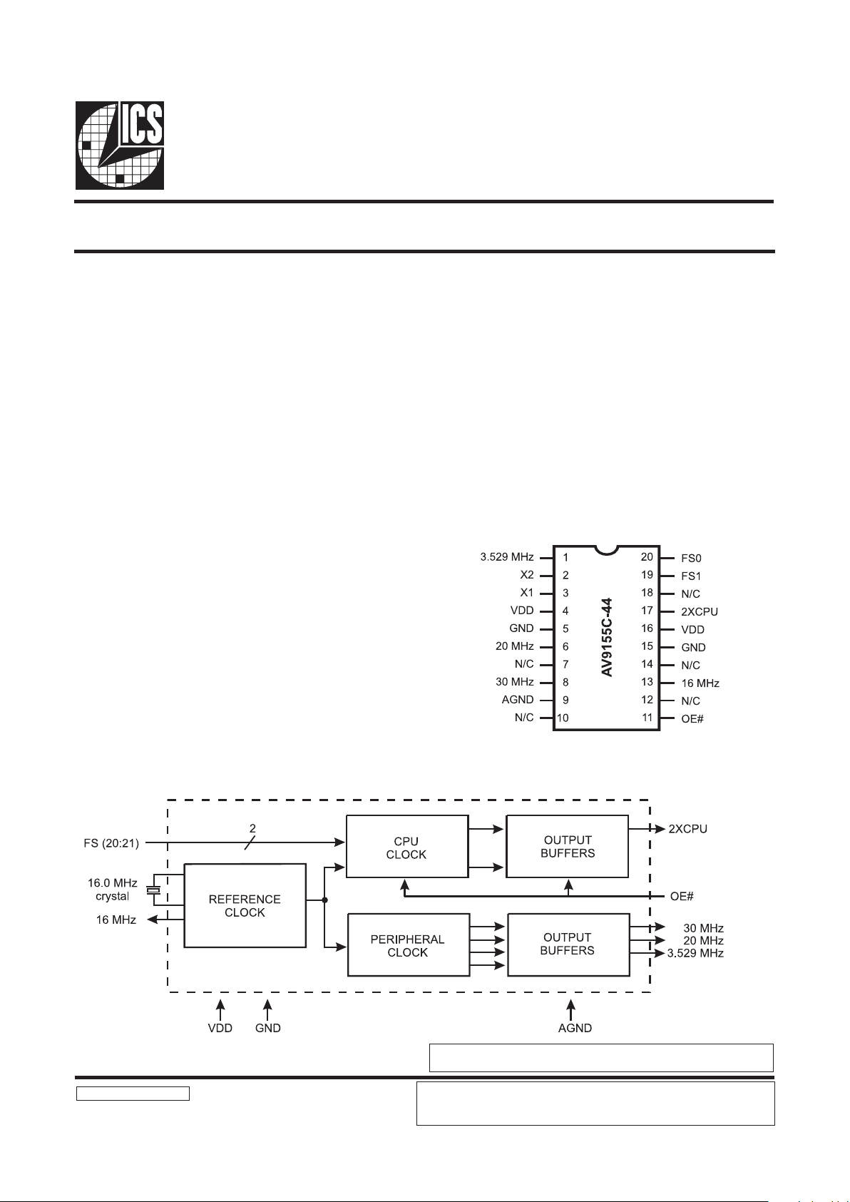
The AV9155C-44 is a low cost frequency generator designed
specifically for desktop and notebook PC applications with
either 3.3V or 5.0V power supply voltage. Its CPU clocks
provide all necessary CPU frequencies for 286, 386 and 486
systems, including support for the latest speeds of processors.
The device uses a 14.318 MHz crystal to generate the CPU
and all peripheral clocks for integrated desktop motherboards.
The dual 14.318 MHz clock outputs allows one output for the
system and one to be the input to an ICS graphics frequency
generator such as the AV9194.
The CPU clock offers the unique feature of smooth, glitchfree transitions from one frequency to the next, making this
ideal device to use whenever slowing the CPU speed. The
AV9155C-44 makes a gradual transition between frequencies,
so that it obeys the Intel cycle-to-cycle timing specification
for 486 systems. The simultaneous 2X and 1X CPU clocks
offer controlled skew to within 1.5ns (max) of each other.
Compatible with 286, 386, and 486 CPUs
Supports turbo modes
Generates communications clock, keyboard clock,
floppy disk clock, system reference clock, bus clock
and CPU clock
Output enable tristates outputs
Up to 100 MHz at 5V or 3.3V
20-pin DIP or SOIC
All loop filter components internal
Skew-controlled 2X and 1X CPU clocks
Power-down option
Pin Configuration
20-Pin DIP or SOIC
THIS DATA SHEET (AV9155C-44) IS AN ADDENDUM TO THE EXISTING AV9155C
DATA SHEET. ALL INFORMATION IN THIS DATA SHEET SUPERSEDES THE DATA
FOUND IN THE ORIGINAL AV9155C DATA SHEET.
ICS reserves the right to make changes in the device data identified in this publication
without further notice. ICS advises its customers to obtain the latest version of all
device data to verify that any information being relied upon by the customer is current
and accurate.
Page 2
2
AV9155C-44
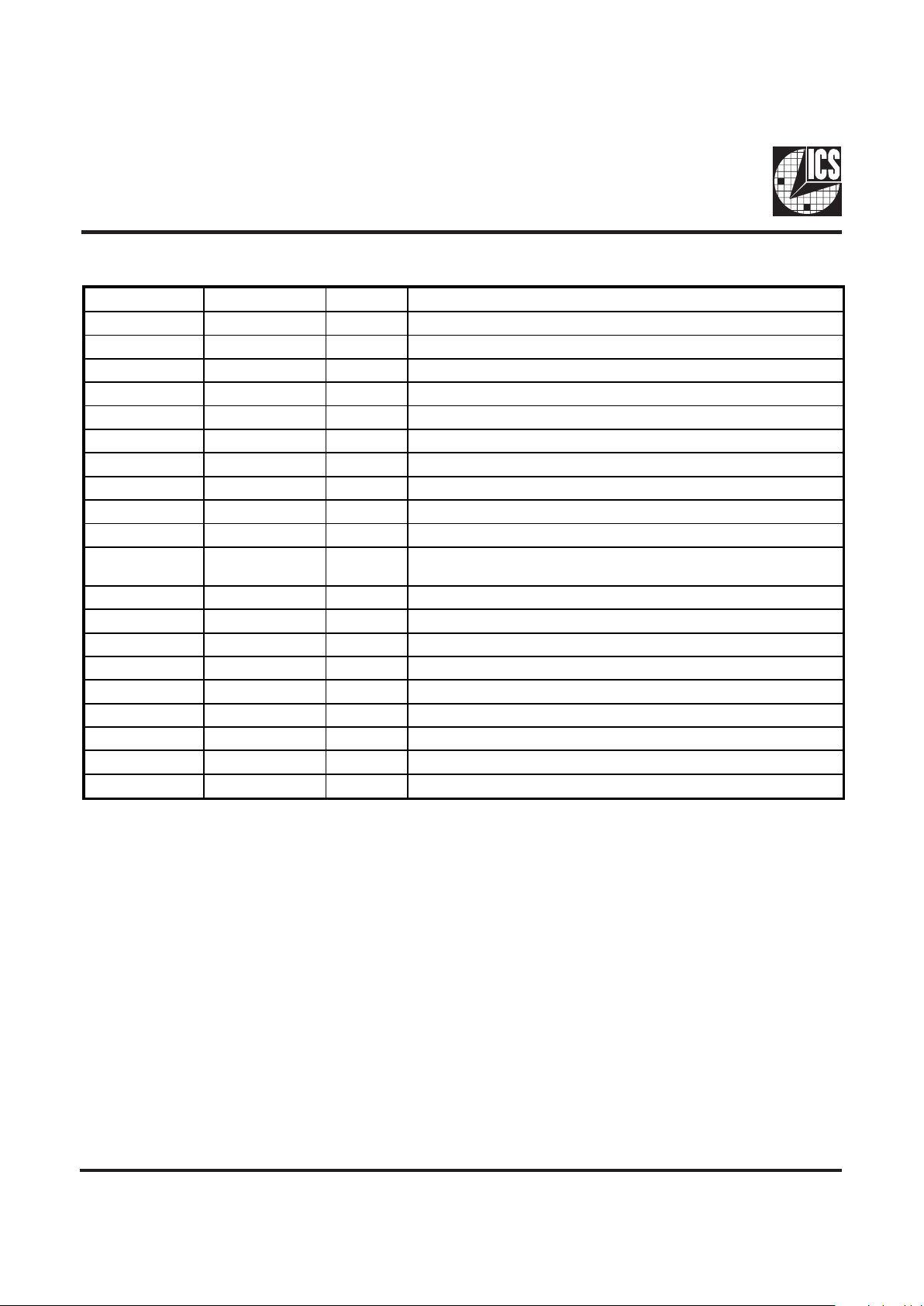
Pin Descriptions for AV9155C-44
PIN NUMBER PIN NAME TYPE DESCRIPTION
1 3.529 MHz OUT 3.529 MHz reference clock output.
2 X2 OUT CRYSTAL connection.
3 X1 IN CRYSTAL connection.
4 VDD PWR DIGITAL POWER SUPPLY (+5V).
5 GND PWR Digital GROUND.
6 20 MHz OUT 20 MHz clock output.
7 N/C - Not internally connected.
8 30 MHz OUT 30 MHz keyboard clock output.
9 AGND PWR ANALOG GROUND (original version).
10 N/C - Not internally connected.
11 OE# IN
OUTPUT ENABLE. Tristates 2XCPU output when high. (Has
internal pull-up.)
12 N/C - Not internally connected.
13 16 MHz OUT 16 MHz reference clock output.
14 N/C - Not internally connected.
15 GND PWR Digital GROUND.
16 VDD PWR DIGITAL POWER SUPPLY (+5V).
17 2XCPU OUT CPU clock output.
18 N/C - Not internally connected.
19 FS1 IN CLOCK frequency SELECT #1. (Has internal pull-up.)
20 FS0 IN CLOCK frequency SELECT #0. (Has internal pull-up.)
Page 3

3
AV9155C-44
Specification Limits (superseding AV9155C general data sheet)
No internal capacitors on crystal pins X1 and X2.
Note: Parameter is guaranteed by design and characterization, not subject to production testing.
PARAMETER SYMBOL TEST CONDITIONS MIN TYP MAX UNITS
Jitter, One Sigma,
1
all clocks 20 to 40 MHz
tj1
sa 10,000 cycles 500 ps
Jitter, One Sigma,
1
clocks below 20 MHz
tj1
sb
10,000 cycles 2.0 %
Jitter, Absolute,
all clocks 20 to 40 MHz
tjab
sa
10,000 cycles -1000 1000 ps
Jitter, Absolute,
1
all clocks below 20 MHz
tjab
sb
10,000 cycles -3.0 3.0 %
Functionality
(Using 16.0 MHz input. All frequencies in MHz.)
CPU
* 5V only
PERIPHERAL CLOCKS
REFERENCE CLOCKS
(Pin 1) (Pin 6) (Pin 8)
3.529 Mhz 20 MHz 30 MHz
(Pin 13)
16 Mhz
FS1
(Pin 19)
FS0
(Pin 20)
2XCPU
(Pin 17)
0 0 20.0
0 1 28.0
1 0 22.59
1 1 39.38
Page 4

4
AV9155C-44
Ordering Information
AV9155C-44CW20
Example:
ICS XXXX-PPP M X#W
Lead Count & Package Width
Lead Count=1, 2 or 3 digits
W=.3 SOIC or .6 DIP; None=Standard Width
Package Type
W=SOIC T&R=Tape and Reel
Pattern Number (2 or 3 digit number for parts with ROM code patterns)
Device Type (consists of 3 or 4 digit numbers)
Prefix
ICS, AV=Standard Device
ICS reserves the right to make changes in the device data identified in this publication
without further notice. ICS advises its customers to obtain the latest version of all
device data to verify that any information being relied upon by the customer is current
and accurate.
SOIC
LEAD COUNT 20L
DIMENSION L 0.504
20 Pin DIP
 Loading...