

Page 1

Philips Semiconductors Linear Products Product specification
AU2903
Low power dual voltage comparator
300
August 31, 1994 853-1636 13721
DESCRIPTION
The AU2903 consists of two independent precision voltage
comparators with an offset voltage specification as low as 2.0mV
max. for two comparators which were designed specifically to
operate from a single power supply over a wide range of voltages.
Operation from split power supplies is also possible and the low
power supply current drain is independent of the magnitude of the
power supply voltage. These comparators also have a unique
characteristic in that the input common-mode voltage range includes
ground, even though operated from a single power supply voltage.
FEATURES
•Wide single supply voltage range 2.0V
DC
to 36VDC or dual
supplies ±1.0V
DC
, to ±18V
DC
•Very low supply current drain (0.8mA) independent of supply
voltage (2.0mW/comparator at 5.0V
DC
)
•Low input biasing current 25nA
•Low input offset current ±5nA and offset voltage ±2mV
•Input common-mode voltage range includes ground
•Differential input voltage range equal to the power supply voltage
•Low output 250mV at 4mA saturation voltage
•Output voltage compatible with TTL, DTL, ECL, MOS and CMOS
logic systems
APPLICATIONS
•A/D converters
•Wide range VCO
•MOS clock generator
•High voltage logic gate
•Multivibrators
PIN CONFIGURATION
1
2
3
4 5
6
7
8
D and N Packages
A B
TOP VIEW
OUTPUT A
INVERTING INPUT A
NON–INVERTING INPUT A
GND
V+
OUTPUT B
INVERTING INPUT B
NON–INVERTING INPUT B
EQUIVALENT CIRCUIT
V
+
100µA3.5µA 3.5µA 100µA
Q1
Q2 Q3
Q4
Q8
Q7
Q6Q5
– INPUT
OUTPUT
+
INPUT
(1 Comparator Only)
ORDERING INFORMATION
DESCRIPTION TEMPERATURE RANGE ORDER CODE DWG #
8-Pin Plastic Small Outline (SO) Package -40°C to +125°C AU2903D 0174C
8-Pin Plastic Dual In-Line Package (DIP) -40°C to +125°C AU2903N 0404B
Page 2

Philips Semiconductors Linear Products Product specification
AU2903
Low power dual voltage comparator
August 31, 1994
301
ABSOLUTE MAXIMUM RATINGS
SYMBOL PARAMETER RATING UNIT
V
CC
Supply voltage 36 or ±18 V
DC
Differential input voltage 36 V
DC
V
IN
Input voltage -0.3 to +36 V
DC
P
DMAX
Maximum power dissipation,
TA=25°C (still-air)
3
N package 1160 mW
D package 780 mW
Output short-circuit to ground
1
Continuous
I
IN
Input current (VIN<-0.3VDC)
2
50 mA
T
A
Operating temperature range
AU2903 -40 to +125 °C
T
STG
Storage temperature range -65 to +150 °C
T
SOLD
Lead soldering temperature (10sec max) 300 °C
NOTES:
1. Short circuits from the output to V+ can cause excessive heating and eventual destruction. The maximum output current is approximately
20mA independent of the magnitude of V+.
2. This input current will only exist when the voltage at any of the input leads is driven negative. It is due to the collector-base junction of the
input PNP transistors becoming forward biased and thereby acting as input diode clamps. In addition to this diode action, there is also lateral
NPN parasitic transistor action on the IC chip. This transistor action can cause the output voltages of the comparators to go to the V+ voltage
level (or to ground for a large overdrive) for the time duration that an input is driven negative. This is not destructive and normal output states
will re-establish when the input voltage, which was negative, again returns to a value greater than -0.3V
DC
.
3. Derate above 25°C, at the following rates:
N package at 9.3mW/°C
D package at 6.2mW/°C
Page 3
Philips Semiconductors Linear Products Product specification
AU2903
Low power dual voltage comparator
August 31, 1994
302
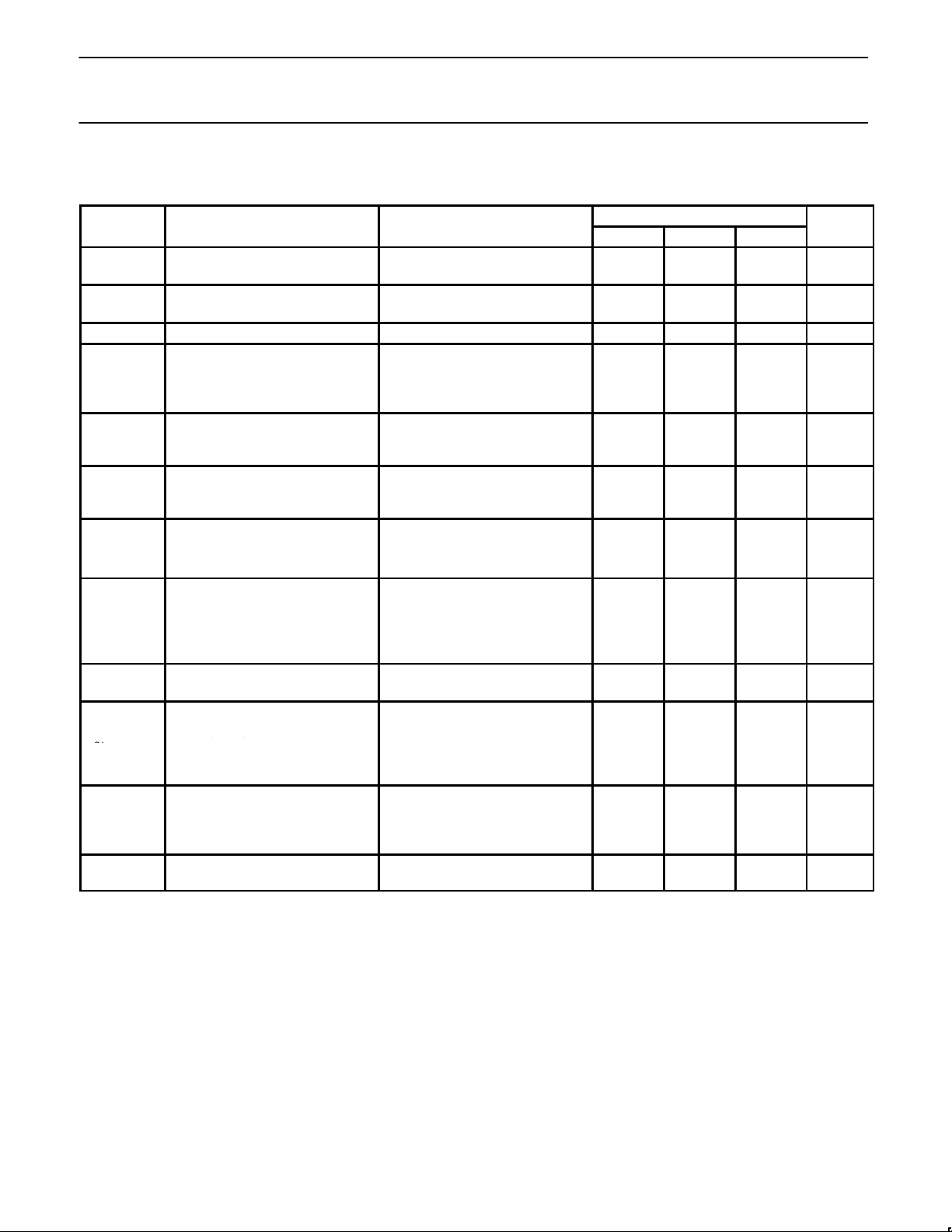
DC AND AC ELECTRICAL CHARACTERISTICS
V+=5VDC, AU2903; -40°C, TA ≤ +125°C, unless otherwise specified.
AU2903
SYMBOL
PARAMETER
TEST CONDITIONS
Min Typ Max
UNIT
V
OS
Input offset voltage
2
T
A
= 25°C
Over temp.
±2.0
±9
±7.0
±15
mV
V
CM
Input common-mode voltage
range
3, 6
T
A
= 25°C
Over temp.
0
0
V+-1.5
V+-2.0
V
V
IDR
Differential input voltage
1
Keep all VINs ≥ 0VDC (or V- if need) V+ V
I
BIAS
Input bias current
4
I
IN(+)
or I
IN(-)
with output
in linear range
T
A
=25°C
Over temp.
25
200
250
500
nA
I
OS
Input offset current
I
IN(+)
- I
IN(-)
T
A
= 25°C
Over temp.
±5
±50
±50
±200
nA
nA
I
OL
Output sink current
V
IN(-)
≥ 1VDC, V
IN(+)
= 0,
V
0
≤ 1.5V
DC
T
A
= 25°C
6.0 16 mA
I
OH
Output leakage current
V
IN(+)
≥ 1VDC, V
IN(-)
= 0
V
0
= 5VDC, T
A
= 25°C 0.1 nA
V
0
= 30VDC, over temp. 1.0 µA
R
L
= ∞ on both
comparators.
I
CC
Supply current T
A
= 25°C 0.8 1 mA
V+ = 30V, over temp. 1 2.5
A
V
Voltage gain
R
L
≥ 15kΩ, V+ = 15VDC,
T
A
= 25°C
25 100 V/mV
V
IN(-)
≥ 1VDC, V
IN(+)
= 0,
I
SINK
≤ 4mA
VOLSaturation voltage
T
A
= 25°C 400 400 mV
Over temp. 700
t
LSR
Large-signal
response time
V
IN
= TTL logic swing,
V
REF
= 1.4VDC
V
RL
= 5VDC, R
L
= 5.1kΩ,
T
A
= 25°C
300 ns
t
R
Response time
5
V
RL
= 5VDC, R
L
= 5.1kΩ
T
A
= 25°C
1.3 µs
NOTES:
1. Positive excursions of input voltage may exceed the power supply level by 17V . As long as the other voltage remains within the
common-mode range, the comparator will provide a proper output state. The low input voltage state must not be less than -0.3V
DC
(V
DC
below the magnitude of the negative power supply, if used).
2. At output switch point, VO ≈ 1.4VDC, R
S
= 0Ω with V+ from 5VDC to 30VDC and over the full input common-mode range (0VDC to
V+-1.5V
DC
).
3. The input common-mode voltage or either input signal voltage should not be allowed to go negative by more than 0.3V . The upper end of the
common-mode voltage range is V+-1.5V , but either or both inputs can go to 30V
DC
without damage.
4. The direction of the input current is out of the IC due to the PNP input stage. This current is essentially constant, independent of the state of
the output so no loading change exists on the reference or input lines.
5. The response time specified is for a 100mV input step with a 5mV overdrive.
6. For input signals that exceed V
CC
, only the over-driven comparator is affected. With a 5V supply, VIN should be limited to 25V maximum,
and a limiting resistor should be used on all inputs that might exceed the positive supply.
Page 4
Philips Semiconductors Linear Products Product specification
AU2903
Low power dual voltage comparator
August 31, 1994
303
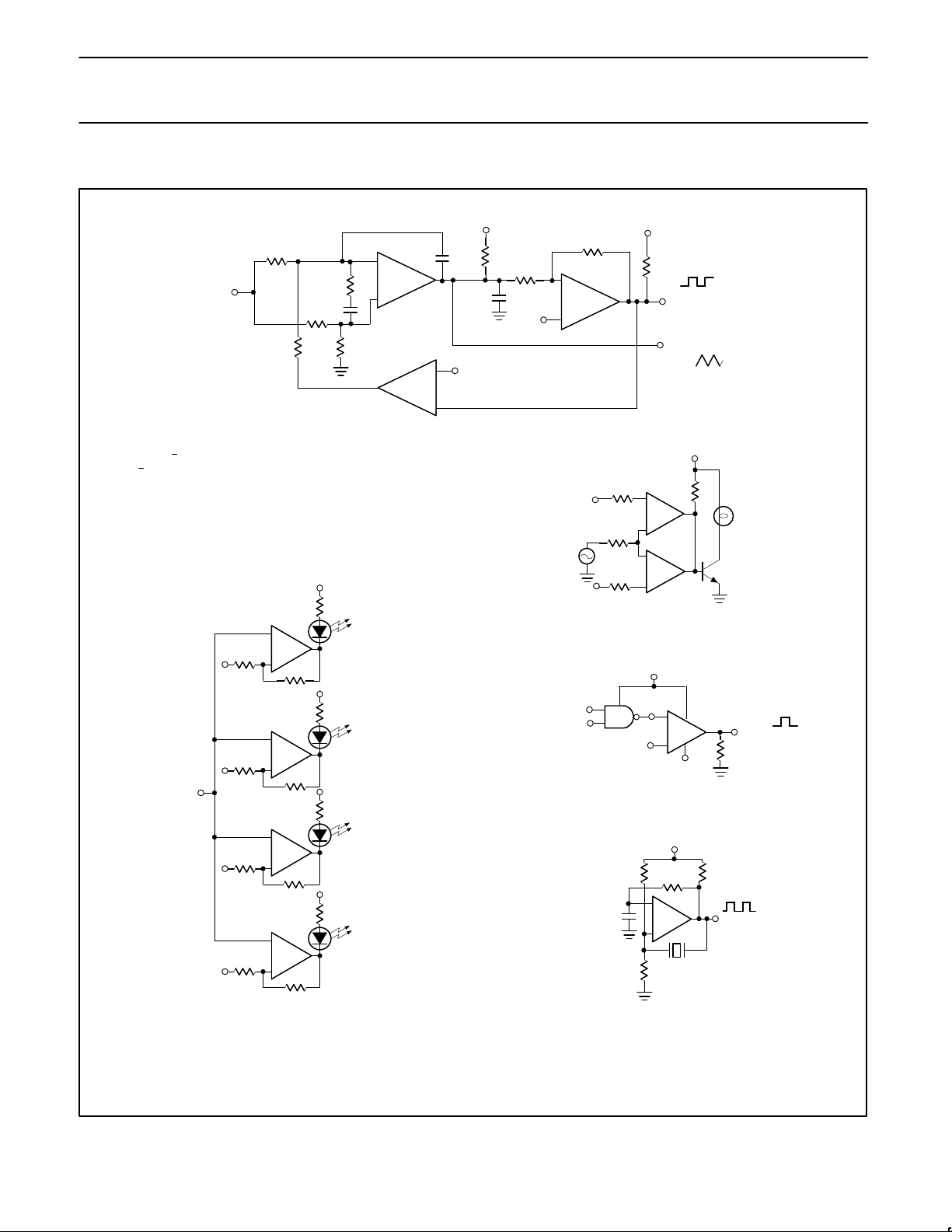
TYPICAL APPLICATIONS
100kΩ
500pF
10
0.1µF
20kΩ
50kΩ
20kΩ
V
+
/2
V
+
30kΩ
5.1kΩ
700kΩ
V
–
/2
–
+
+ VC
FREQUENCY
CONTROL
VOLTAGE
INPUT
3.0kΩ
OUTPUT 1
OUTPUT 2
–
+
–
+
+
V
REF
HI
+
V
IN
2R
S
R
S
2R
S
+
V (12VDC)
10KΩ
LAMP
2N2222
+
–
+
–
+
–
+
5V
DC
360
100
100k
+
–
+
5V
DC
360
100
100k
+
–
+
5V
DC
360
100
100k
+
–
+
5V
DC
360
100
100k
+
V
REF 4
+
V
REF 3
+
V
REF 2
+
V
REF 1
V
O
+
–
V
+
2.0kΩ
V
+
0
V
O
1 – 100kHz
CRYSTAL
200kΩ
200kΩ
100kΩ
0.1µF
Crystal–Controlled Oscillator
Limit Comparator
Two–Decade High–Frequency VCO
Visible Voltage Indicator
NOTES:
V+ = 30V
DC
+ 250m VDC < VC = 50V
DC
700H < fO = 100kHz
NOTE:
Input of unused comparators should be grounded.
+
–
TTL–to–MOS Logic Converter
5V
DC
+V
REF
1.4V
DC
10KΩ
V
O
o
-12V
+V
REF
LOW
V
+
.01µF
–12V
DC
Page 5
Philips Semiconductors Linear Products Product specification
AU2903
Low power dual voltage comparator
August 31, 1994
304
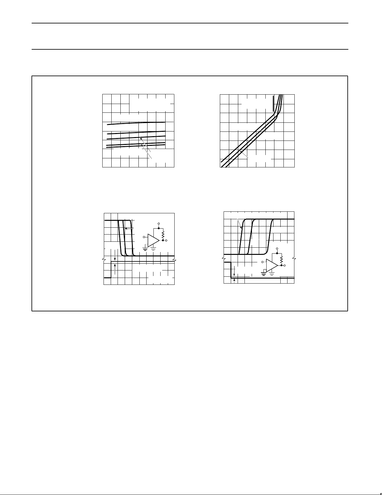
TYPICAL PERFORMANCE CHARACTERISTICS
INPUT VOLTAGE
V — mV
IN
OUTPUT VOLTAGE
V — mV
O
V
OUT
V
IN
–
+
+
5V
80
60
40
20
0 10 20 30 40
v + — SUPPLY VOLTAGE — V
DC
I — INPUT CURRENT — nA
N DC
TA = -55oC
TA = 0oC
TA = +70oC
TA = +25oC
TA = +125oC
V
IN (CM)
= 0 V
DC
R
IN (CM)
= 10kΩ
OUT OF
SATURATION
TA = +125oC
TA = -55oC
TA = +25
o
10
1.0
0.1
0.01
0.001
0.01 0.1 1.0 10 100
I
O
— OUTPUT SINK CURRENT (mA)
V — SATURATION VOLTAGE (V )
O DC
6
5
4
3
2
1
0
0
–50
–100
0 0.5 1.0 1.5 2.0
TIME — µ sec
INPUT VOLTAGE
V — mV
IN
OUTPUT VOLTAGE
V — mV
O
5mV = INPUT OVERDRIVE
100mV
OVERDRIVE
TA = 25oC
5.1K
V
OUT
V
IN
20mV
–
+
+
5V
INPUT OVERDRIVE = 100mV
20mV
5mV
OVERDRIVE
6
5
4
3
2
1
0
0
–50
–100
0 0.5 1.0 1.5 2.0
TIME — µ sec
TA = 25oC
5.1K
Input Current Output Saturation Voltage
Response Time for Various
Input Overdrives —
Negative Transition
Response Time for Various
Input Overdrives —
Positive Transition
 Loading...