

Page 1

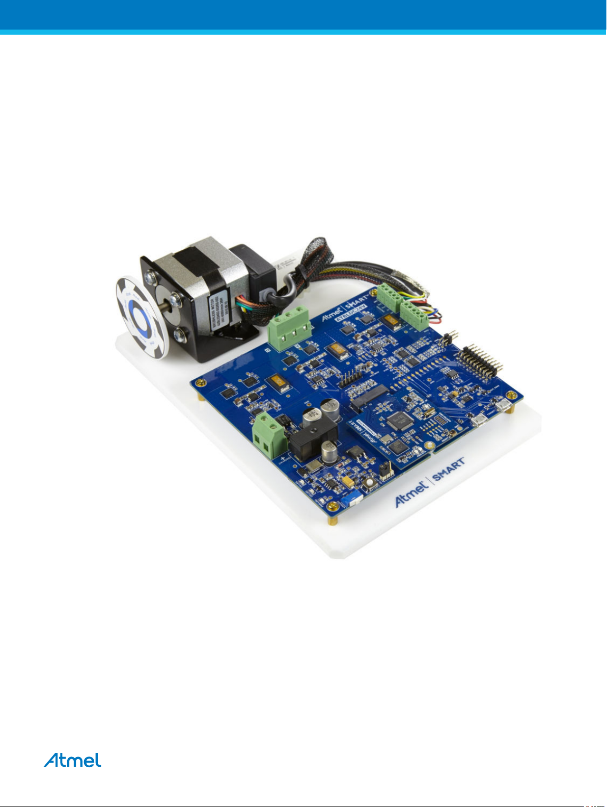
SMART ARM-based Motor Control Kit
ATSAMD21BLDC24V-STK
USER GUIDE
Atmel-42681A-SMART-ARM-based-Motor-Control-Kit_User Guide-02/2016
Page 2

Table of Contents
1. Atmel Low Voltage Motor Control Starter Kit............................................................. 3
1.1. ATSAMD21BLDC24V-STK Features............................................................................................3
1.2. ATSAMD21BLDC24V-STK Kit Content........................................................................................4
1.3. Design Documentation and Relevant Links................................................................................. 5
2. Getting Started with ATSAMD21BLDC24V-STK....................................................... 6
3. ATSAMD21BLDC24V-STK Hardware..................................................................... 12
3.1. ATSAMD21BLDC24V-STK MCU Board.....................................................................................12
3.2. ATSAMD21BLDC24V-STK Driver Board....................................................................................13
3.3. ATSAMD21BLDC24V-STK MCU-driver Interface...................................................................... 23
4. Hardware Revision History and Known Issues........................................................26
4.1. Identifying Product ID and Revision........................................................................................... 26
4.2. Revision......................................................................................................................................26
5. Product Compliance................................................................................................ 27
6. Revision History.......................................................................................................28
Atmel ATSAMD21BLDC24V-STK [USER GUIDE]
Atmel-42681A-SMART-ARM-based-Motor-Control-Kit_User Guide-02/2016
2
Page 3
1. Atmel Low Voltage Motor Control Starter Kit
The Atmel® ATSAMD21BLDC24V-STK is a low voltage BLDC, PMSM motor control starter kit. The kit
contains a driver board hardware with half-bridge power MOSFET drivers, current and voltage sensing
circuit, Hall and Encoder interface, fault protection circuits, etc. The ATSAMD21MOTOR MCU card is
plugged into the driver board and has an on-board debugger. Supported by the Atmel studio integrated
development platform, the kit provides easy access to the features of ATSAMD21J18A MCU and explains
how to integrate the device in a custom motor control application. Pluggable MCU cards are available
from Atmel, supporting other SMART ARM® MCUs.
1.1. ATSAMD21BLDC24V-STK Features
ATSAMD21BLDC24V-STK has the following features:
• Pluggable MCU card interface
• Debug support using on-board Atmel EDBG device
• Three half-bridge MOSFET driver
• Motor BEMF sensing
• Motor individual phase current sensing
• DC-bus voltage sensing
Atmel ATSAMD21BLDC24V-STK [USER GUIDE]
Atmel-42681A-SMART-ARM-based-Motor-Control-Kit_User Guide-02/2016
3
Page 4
• Hall sensor interface
• Encoder sensor interface
• Over-current protection support
• Over-voltage protection at 30VDC
• 5V and 3.3V MCU card support
• Selectable MCU supply voltage
• Reverse power supply voltage protection
• Atmel Xplained Pro compatible header interface
• On board Temperature sensor
• On board serial flash
• LED fault indications
• Atmel studio plug-and-use support using unique ID device
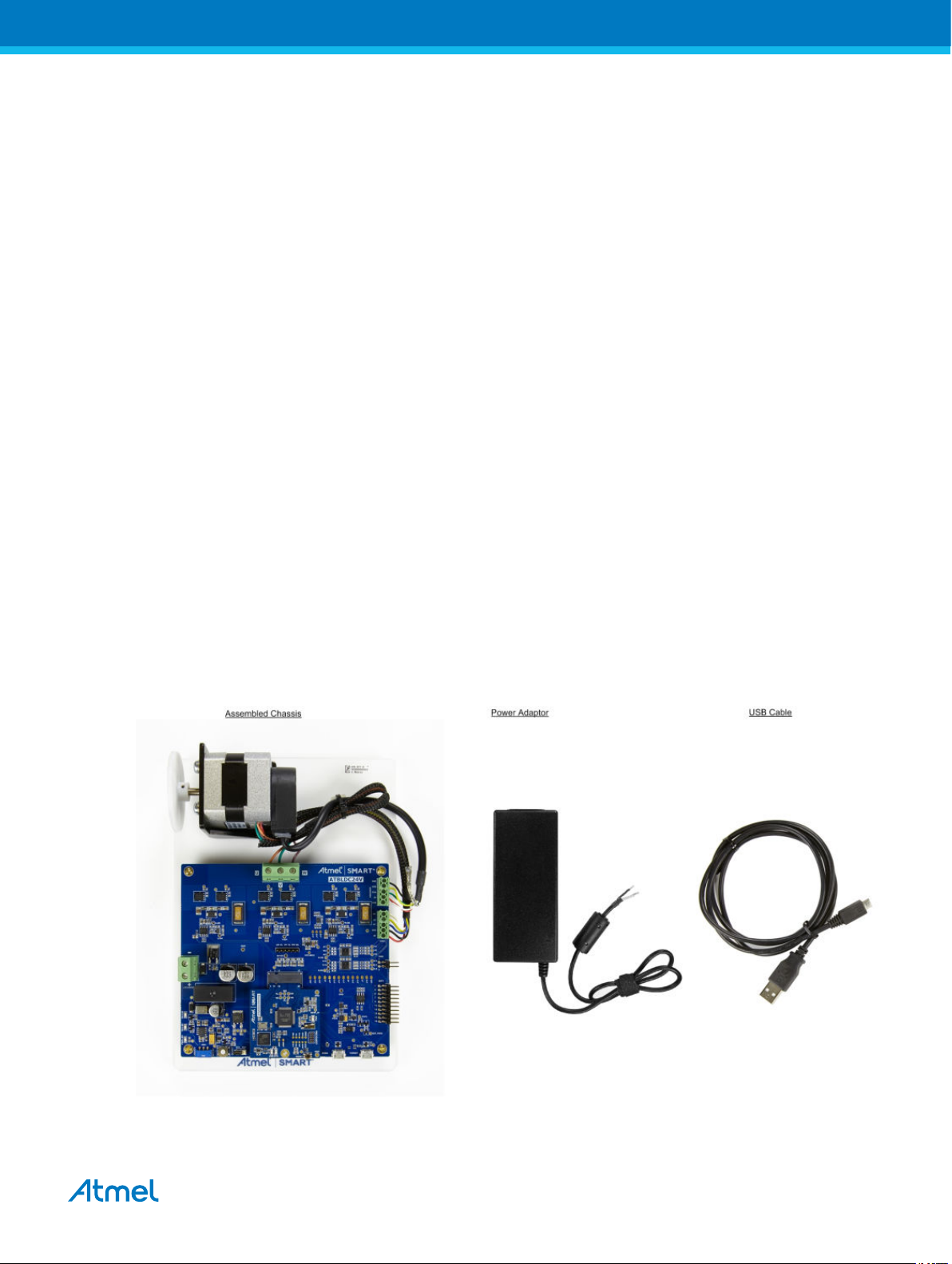
1.2. ATSAMD21BLDC24V-STK Kit Content
ATSAMD21BLDC24V-STK Kit contains the PCBs, BLDC motor, power adaptor and USB cable to get
started and running the motor in the kit.
The kit contains the following items:
1. AT24VBLDC driver board.
2. ATSAMD21MOTOR MCU card.
3. LDO brush-less DC motor (LDO: 42BL02402-0026B-002).
4. Fully assembled chassis plate.
5. 24V, 4A AC adapter (EDAC: EA11011E-240).
6. Micro-USB cable.
Figure 1-1. ATSAMD21BLDC24V-STK Kit Content
Atmel ATSAMD21BLDC24V-STK [USER GUIDE]
Atmel-42681A-SMART-ARM-based-Motor-Control-Kit_User Guide-02/2016
4
Page 5

1.3. Design Documentation and Relevant Links
The following list contains links to the most relevant documents and software for ATSAMD21BLDC24VSTK:
• Xplained Pro products - Atmel Xplained Pro is a series of small-sized and easy-to-use evaluation
kits for Atmel microcontrollers and other Atmel products. It consists of a series of low-cost MCU
boards for evaluation and demonstration of features and capabilities of different MCU families.
• ATSAMD21BLDC24V-STK User Guide - PDF version of this User Guide.
• ATSAMD21BLDC24V-STK Design Documentation - Package containing schematics, BOM,
assembly drawings, 3D plots, layer plots, etc.
• Atmel Studio - Free Atmel IDE for development of C/C++ and assembler code for Atmel
microcontrollers.
• EDBG User Guide - User guide containing more information about the on-board Embedded
Debugger.
• Atmel Data Visualizer - Atmel Data Visualizer is a program used for processing and visualizing
data. Data Visualizer can receive data from various sources such as the Embedded Debugger Data
Gateway Interface found on Xplained Pro boards and COM ports.
• ATSAMD21BLDC24V-STK - Product page.
• ATSAMD21J18A - MCU datasheet.
Atmel ATSAMD21BLDC24V-STK [USER GUIDE]
Atmel-42681A-SMART-ARM-based-Motor-Control-Kit_User Guide-02/2016
5
Page 6
2. Getting Started with ATSAMD21BLDC24V-STK
This chapetr is a step-by-step guide to get started with the SAMD21BLDC24V-STK.
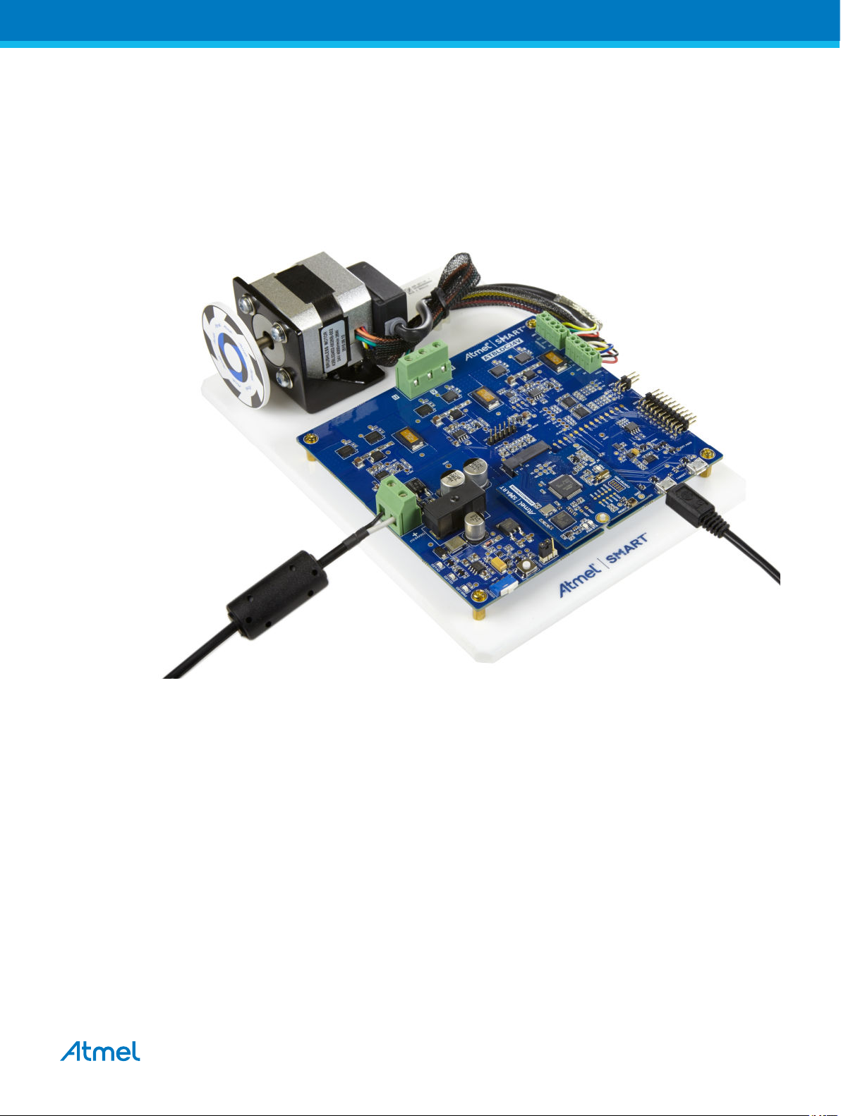
1. SAMD21BLDC24V-STK kit contains a fully assembled chassis and 24VDC power adaptor.
2. Connect the power adaptor to the “SUPPLY-IN connector”. Connect white color cable to + PIN.
Figure 2-1. Kit with Power and USB Ports Connected
3. Switch ON the power adaptor.
4. Connect the Micro-USB cable to the “EDBG-USB connector” and PC USB port.
5. The power LED indications on the MCU board are now ON.
6. Open "Data Visualizer".
7. In the "Data Visualizer Connect Window" Choose the kit from the DGI control panel's drop down
list.
Atmel ATSAMD21BLDC24V-STK [USER GUIDE]
Atmel-42681A-SMART-ARM-based-Motor-Control-Kit_User Guide-02/2016
6
Page 7

Figure 2-2. Data Visualizer Connect Window
8. Click "Connect". The orange LED in the MCU board shall now blink.
9. The Data Visualizer default window will pop up once the connection is made. All the fields shall
show default values.
Atmel ATSAMD21BLDC24V-STK [USER GUIDE]
Atmel-42681A-SMART-ARM-based-Motor-Control-Kit_User Guide-02/2016
7
Page 8
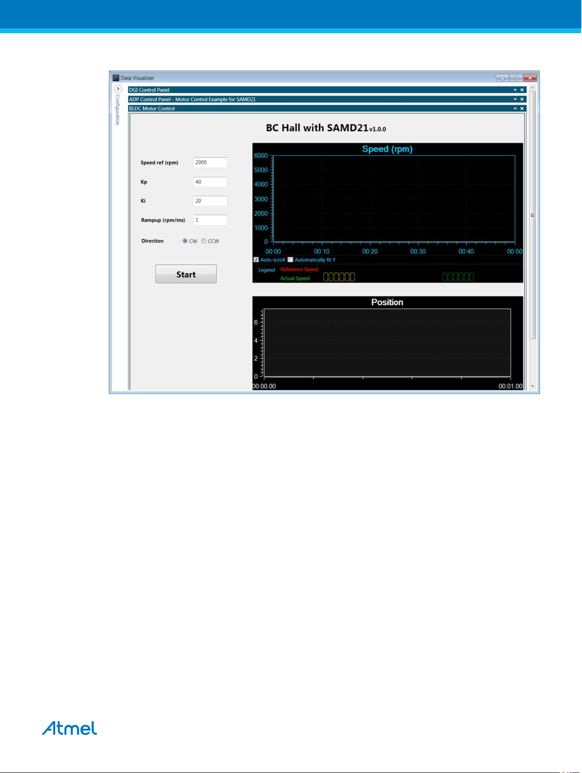
Figure 2-3. Data Visualizer Start Window
10. Click on "Start" to turn the motor ON with default values.
Atmel ATSAMD21BLDC24V-STK [USER GUIDE]
Atmel-42681A-SMART-ARM-based-Motor-Control-Kit_User Guide-02/2016
8
Page 9
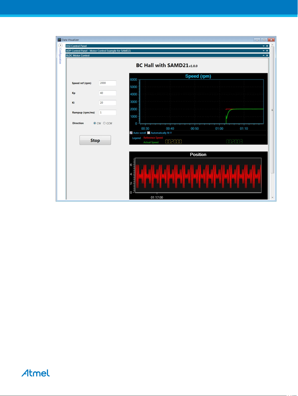
Figure 2-4. Data Visualizer "Start Motor" Window
11. Change the value in a field and press "Enter". For instance, to change the motor speed, type in the
desired speed within the motor's rating and press "Enter".
Atmel ATSAMD21BLDC24V-STK [USER GUIDE]
Atmel-42681A-SMART-ARM-based-Motor-Control-Kit_User Guide-02/2016
9
Page 10

Figure 2-5. Data Visualizer "Change Parameter"
12. Stop the Motor by clicking the "Stop" button.
13. To change direction of rotation after "Stop", choose "CCW" in radio button and click "Start".
Atmel ATSAMD21BLDC24V-STK [USER GUIDE]
Atmel-42681A-SMART-ARM-based-Motor-Control-Kit_User Guide-02/2016
10
Page 11

Figure 2-6. Data Visualizer "Change Direction"
14. Adjust the graph by checking "Automatically fit Y".
Atmel ATSAMD21BLDC24V-STK [USER GUIDE]
Atmel-42681A-SMART-ARM-based-Motor-Control-Kit_User Guide-02/2016
11
Page 12

3. ATSAMD21BLDC24V-STK Hardware
The ATSAMD21BLDC24V-STK has a two-board architecture. The driver base board contains drive
circuits, sensor circuits, protection circuits, power supply, etc., and the MCU board (MCU card) contains
the MCU, clock circuit, and debug circuit. The MCU card is inserted into the 67-pin NGFF standard
interface on the driver board. The ATSAMD21BLDC24V-STK comes with an ATSAMD21J18A MCU card.
3.1. ATSAMD21BLDC24V-STK MCU Board
The main components in the ATSAMD21MOTOR MCU card are highlighted in the PCB and block
diagram given below.
Figure 3-1. MCU Board PCB
Atmel ATSAMD21BLDC24V-STK [USER GUIDE]
Atmel-42681A-SMART-ARM-based-Motor-Control-Kit_User Guide-02/2016
12
Page 13

Figure 3-2. MCU Board Block Diagram
3.1.1. Power Supply
The ATSAMD21MOTOR MCU card takes 3.3VDC supply from the 67-pin edge connector. Both the
EDBG device and the Main MCU operates from 3.3VDC. The power supply selection jumper on the
Driver board should be connected to 3V3 (silk screen text) selection.
3.1.2. Main MCU Circuit
The ATSAMD21MOTOR has an ATSAMD21J18A device. The device is intended to work with MCU
internal clock source. A 32.768kHz crystal is connected externally to the MCU.
3.1.3. Embedded Debugger
The ATSAMD21J18A MCU is interfaced to the EDBG debug device. The EDBG uses SWD interface for
programming and debugging the main MCU. A debug header is also provided on the MCU board with
ARM Cortex® debug pinout. An external debugger can be connected to this debug port.
The DGI is a proprietary communication interface used by the Atmel Data Visualizer software to
communicate with the development kits through the EDBG. SERCOM4 of the ATSAMD21J18A
connected to the EDBG device support DGI SPI interface and uses Atmel ADP protocol. The MCU
SERCOM4 is also connected to the UART channel of the EDBG through a pair of "normally open"
jumpers, the J200 and J201. Shorting these jumpers will enable the CDC UART interface for the main
MCU.
High Speed USB port of the EDBG is accessible at the driver board. EDBG USB enumerates as a
composite device supporting debug, DGI SPI, and CDC interfaces.
The USB port of the ATSAMD21J18A is connected to the Micro-USB connecter on the driver board.
3.2. ATSAMD21BLDC24V-STK Driver Board
The driver board contains half-bridge MOSFET driver circuits for three-phase BLDC, PMSM motor drive
and supports 12-24VDC recommended bus drive voltage. Individual phase current sense, bus voltage
sense, and back-EMF sense circuits supports development of sensor-less motor drive algorithms. Hall
and Encoder sensor interfaces enables the user to develop sensor-based motor control applications. The
Atmel ATSAMD21BLDC24V-STK [USER GUIDE]
Atmel-42681A-SMART-ARM-based-Motor-Control-Kit_User Guide-02/2016
13
Page 14

driver board has over-voltage protection in hardware and over-current shutdown through the MCU input.
Reverse voltage protection is available at 12-24VDC and EXT1-header external supply inputs. USB
interface headers are interfaced to the main MCU and EDBG device in the MCU board. Temperature
sensor, serial flash, XPRO interface header, and UID chip circuits are the other features included in the
driver board hardware. The figure below shows the main components and block diagram of driver board.
Figure 3-3. ATSAMD21BLDC24V-STK Driver Board PCB
Atmel ATSAMD21BLDC24V-STK [USER GUIDE]
Atmel-42681A-SMART-ARM-based-Motor-Control-Kit_User Guide-02/2016
14
Page 15

Figure 3-4. ATSAMD21BLDC24V-STK Block Diagram
3.2.1. Half-bridge FET Driver
The half-bridge circuit is based on the NTMFS5C646NL N-channel Power MOSFET. Each half-bridge is
driven by the NCP5106A gate driver. The gate driver takes two independent PWM inputs from the MCU
and uses bootstrap technique to drive the high side Power MOSFET in the half-bridge. The bootstrap
capacitor is tied between PIN5 and PIN8 of the NCP5106 through a resistor. C5 is the bootstrap capacitor
and D1 is the bootstrap diode for phase-U half-bridge, as shown in the figure below. The bootstrap
capacitor value is chosen based on the total charge to be supplied by the capacitor and maximum
allowable voltage drop on the bootstrap capacitor.
Atmel ATSAMD21BLDC24V-STK [USER GUIDE]
Atmel-42681A-SMART-ARM-based-Motor-Control-Kit_User Guide-02/2016
15
Page 16

Figure 3-5. Half-bridge Driver Schematic
3.2.2. Power Supply
The driver board has multiple power supply selection options. Automatic supply input selection is similar
to the Atmel Xplained Pro hardware. The block diagram shows how to use the SW1 user switch and the
jumper available on the PCB to select the MCU voltage supply.
Figure 3-6. Driver Board Power Supply
3.2.3. Phase Current Sense
The current sense resistor and the differential amplifier circuit enables measurement of individual phase
currents using the ADC channel of the MCU. The figure below shows the sense circuit for the U-phase
and reference generator. R30 is the current shunt and op-amp U8 is configured in inverting differential
amplifier configuration. Voltage offset is added to the sense output, which is the reference voltage output
generated from the MCU supply voltage (MCU supply divided by 2). Solving the circuit,
Vout = Vr-(Is.Rs)(R52/R16)
Vout = U_I_sense at TP13
Vr = reference voltage (= 1.65V)
Is = phase current
Rs = shunt resistor
Atmel ATSAMD21BLDC24V-STK [USER GUIDE]
Atmel-42681A-SMART-ARM-based-Motor-Control-Kit_User Guide-02/2016
16
Page 17

R52 = feedback resistor
R16 = input side resistor
Figure 3-7. Current Sense and Reference Generation Circuit
3.2.4. BEMF, DC Bus Sense
Back-EMF generated in the phase windings can be determined from the voltage read at the individual
phase terminals. A schematic drawing for the voltage scaling and the filter circuit is shown in the figure
below. BEMF output is connected to the ADC and analog comparator of the MCU. Motor DC supply is
divided by network R79, R80 and connected to ADC reference and analog comparator.
Figure 3-8. Back-EMF, DC Bus Voltage Sense Circuit
3.2.5. Over-voltage Protection (OVP)
DC bus voltage is monitored by the voltage sense circuit. If the voltage gets higher than 30VDC, the overvoltage protection will shut down the FET driver. The OVP circuit is shown in the figure below. Sense
voltage is determined by the zener diode (D7) voltage (28V) and R-network R117 and R118. Vgs
(threshold) of Q8A is typically 2V.
Atmel ATSAMD21BLDC24V-STK [USER GUIDE]
Atmel-42681A-SMART-ARM-based-Motor-Control-Kit_User Guide-02/2016
17
Page 18

Figure 3-9. OVP Circuit
3.2.6. Over-current Protection
Over-current protection (OCP OFF) is signaled from the MCU when the total individual phase shunt
current value exceeds the limit. Shutdown circuit is shown in the image below. Q8B will be OFF in normal
operation and switches ON and shuts off U5 when OCP OFF triggers. Shutting down U5 will cut off the
MOSFET driver and can be switched back to active condition by pressing the SW2 push button.
Figure 3-10. Over-current Protection Circuit
3.2.7. Hall Sensor Interface
The Hall sensor interface uses NTS0104 level translator. The interface is tested with motors with open
drain and push pull type Hall sensor output. The LDO motor supplied with ATSAMD21BLDC24V-STK has
open drain Hall sensor output type.
Atmel ATSAMD21BLDC24V-STK [USER GUIDE]
Atmel-42681A-SMART-ARM-based-Motor-Control-Kit_User Guide-02/2016
18
Page 19

3.2.8. Encoder Sensor Interface
The encoder sensor interface uses a NTS0104 level translator. The interface is tested with motors with
open drain and push pull type encoder sensor output. The LDO motor supplied with
ATSAMD21BLDC24V-STK has open drain output type.
3.2.9. Atmel Xplained PRO Interface
The Xplained PRO compatible header has a 20-pin EXT1 connector and a 4-pin power connector. All the
lines of the 20-pin header are routed to the 67-pin NGFF interface. Some pins of the header are not
connected to the MCU ports, also some pins are connected to other features on the driver board. This is
based on the availability of pins on the MCU card. The table below shows the pinout for both the
connectors in the case of ATSAMD21MOTOR MCU card supplied with the kit.
Table 3-1. EXT1- Xplained PRO Extension Header
Pin Pin name 67-pin interface Driver board connections SAMD21J18A port
1 ID_2 4 EDBG_ID2/EXT1_1 EDBG_PB01
2 GND 67 - GND
3 ADC(+) 20 EXT_3 NC
4 ADC(-) 35 EXT1_4(GPIO10) NC
5 GPIO5 22 EXT1_5(GPIO5) PB31
6 GPIO6 23 EXT1_6(GPIO6) PA17
7 PWM(+) 18 EXT1_7(GPIO1) PA19
8 PWM(-) 19 EXT1_8(GPIO2) PB08
9 IRQ/GPIO 37 EXT1_9(GPIO12) NC
10 SPI_SS_B/GPIO 36 EXT1_10(GPIO11) NC
11 TWI_SDA 12 TEMP_SDA, EXT1_11 PA22
12 TWI_SCL 13 TEMP_SCL, EXT_12 PA23
13 UART_RX 26 RXD_ EXT1_13 PA13
14 UART_TX 27 TXD_EXT1_14 PA12
15 SPI_SS_A 34 EXT_15 PA02
16 SPI_MOSI 17 SPI_MOSI, EXT1_16 PB16
17 SPI_MISO 15 SPI_MISO, EXT1_17 PA20
18 SPI_SCK 16 SPI_SCK, EXT1_18 PB17
19 GND 67 - -
20 VCC_P 63 VCC_P VCC_TARGET_P3V3
Table 3-2. Xplained PRO Power Header
Pin Signal name Description
1 VCC_EXT_P5V0 External 5VDC input
2 GND Ground
Atmel ATSAMD21BLDC24V-STK [USER GUIDE]
Atmel-42681A-SMART-ARM-based-Motor-Control-Kit_User Guide-02/2016
19
Page 20

3 VCC_P5V0 5V
4 VCC_P MCU Voltage
3.2.10. Temperature Sensor
The temperature sensor is placed adjacent to the MOSFET drive circuit to sense the board temperature.
The AT30TSE758 temperature sensor is connected to the MCU through I2C and SMBus compatible 2wire interface and has 7-bit I2C address 1001111.
Table 3-3. I2C Pin Connection
Signal 67Pin # SAMD21J18A MCU pin Indented MUX function
TEMP SDA 12 PA22 SERCOM3(PAD0)
TEMP SCL 13 PA23 SERCOM3(PAD1)
TEMP alert 24 PB30 IO
3.2.11. Serial Flash
The AT25DF0181A 8Mb serial flash is connected to the MCU through SPI interface. Some of the pins are
routed to the EXT1 header as given in the table below.
Table 3-4. Flash Pin Connection
Signal 67Pin # SAMD21J18A MCU pin Indented MUX function Other connection
FLASH SS 14 PA21 SERCOM5(PAD3)
FLASH MISO 15 PA20 SERCOM5(PAD2) EXT1_17
FLASH SCK 16 PB17 SERCOM5(PAD1) EXT1_18
FLASH MOSI 17 PB16 SERCOM5(PAD0) EXT1_16
3.2.12. UID Identification Chip
The UID chip is a unique ID chip used by the EDBG interface to enable automatic board identification in
Atmel Studio. When the motor control evaluation board is connected to the USB port the Atmel studio
recognizes it and load the necessary software and documentation.
3.2.13. USB Communication Interface
The driver board has EDBG and MCU Micro-USB headers. EDBG USB is connected to the HS USB port
of the EDBG device in the MCU card. MCU USB is connected to the USB port of the MCU in the MCU
card plugged in.
3.2.14. Debug Test Points
Test points are available on the driver board for probing debug signals. Proper silk screen text is provided
on the PCB to identify the test points. Some of the most useful test points are highlighted in the image
below.
Atmel ATSAMD21BLDC24V-STK [USER GUIDE]
Atmel-42681A-SMART-ARM-based-Motor-Control-Kit_User Guide-02/2016
20
Page 21

Figure 3-11. Debug Test Points on the Driver Board
3.2.15. Motor Specification
Specification and wiring for the motor are given in the figure below.
Atmel ATSAMD21BLDC24V-STK [USER GUIDE]
Atmel-42681A-SMART-ARM-based-Motor-Control-Kit_User Guide-02/2016
21
Page 22

Figure 3-12. Motor Specification
Atmel ATSAMD21BLDC24V-STK [USER GUIDE]
Atmel-42681A-SMART-ARM-based-Motor-Control-Kit_User Guide-02/2016
22
Page 23

3.3. ATSAMD21BLDC24V-STK MCU-driver Interface
Atmel low voltage motor control solution support plugable MCU cards. The MCU card and driver interface
is a standard 67-pin interface as given in table below.
Table 3-5. MCU-driver Interface Pin-out
PIN INTERFACE NAME DRIVER BOARD SAMD21J18A PIN SAMD21 FUNCTION
1 EDBG USB HSP EDBG_USB_HS_P EDBG_USB_HS_P EDBG_USB_HS_N
2 NC NC NC NC
3 EDBG USB HSN EDBG_USB_HS_N EDBG_USB_HS_N EDBG_USB_HS_N
4 EDBG ID2 EDBG_ID2/EXT1_1 EDBG_PB01 EDBG
5 NC NC NC NC
6 EDBG ID1 EDBG_ID1 EDBG_PA28 EDBG
7 MCU USB DP TARGET_USB_HS_P PA25 USB_DN
8 TARGET USB VBUS VCC_TARGET_USB_
NC NC
P5V0
9 MCU USB DN TARGET_USB_HS_N PA24 USB_DP
10 EDBG USB VBUS VCC_EDBG_USB_P5V0VCC_EDBG_USB_P5V0VCC_EDBG_USB_P5
V0
11 TARGET_USB_ID TARGET_USB_ID NC NC
12 TEMP SDA TEMP_SDA, EXT1_11 PA22 SERCOM3(PAD0)
13 TEMP SCL TEMP_SCL, EXT_12 PA23 SERCOM3(PAD1)
14 FLASH SS SPI_SS PA21 SERCOM5(PAD3)
15 FLASH MISO SPI_MISO, EXT1_17 PA20 SERCOM5(PAD2)
16 FLASH SCK SPI_SCK, EXT1_18 PB17 SERCOM5(PAD1)
17 FLASH MOSI SPI_MOSI, EXT1_16 PB16 SERCOM5(PAD0)
18 MCU GPIO1 EXT1_7(GPIO1) PA19 (0) I/O, EXTINT8
(Encoder)
19 MCU GPIO2 EXT1_8(GPIO2) PB08 I/O
20 MCU GPIO3 EXT_3 NC I/O
21 MCU GPIO4 NC(GPIO4) NC I/O
22 MCU GPIO5 EXT1_5(GPIO5) PB31 I/O
23 MCU GPIO6 EXT1_6(GPIO6) PA17 I/O
24 MCU GPIO7 Temp_Alert(GPIO7) PB30 I/O
25 OCP OCP(GPIO8) PB03 I/O
26 EXT1 RXD RXD_ EXT1_13 PA13 SERCOM2(PAD1)
27 EXT1 TXD TXD_EXT1_14 PA12 SERCOM2(PAD0)
Atmel ATSAMD21BLDC24V-STK [USER GUIDE]
Atmel-42681A-SMART-ARM-based-Motor-Control-Kit_User Guide-02/2016
23
Page 24

28 PWM UH PWM_UH PA08 W00(TCC0)
29 PWM UL PWM_UL PA14 W04(TCC0)
30 PWM VH PWM_VH PA09 W01(TCC0)
31 PWM VL PWM_VL PA15 W05(TCC0)
32 PWM WH PWM_WH PA10 W02(TCC0)
33 PWM WL PWM_WL PA16 W06(TCC0)
34 MCU_GPIO8 EXT_15 PA02 AIN0 (ADC)
35 ATA RESET EXT1_4(GPIO10) NC I/O
36 ATA WD EXT1_10(GPIO11) NC I/O
37 ATA SLEEP EXT1_9(GPIO12) NC I/O
38 USHUNT_ADC USHUNT_ADC PB04 AIN12(ADC)
39 VSHUNT_ADC VSHUNT_ADC PB05 AIN13(ADC)
40 WSHUNT_ADC WSHUNT_ADC PA11 AIN19(ADC)
41 MOTOR VDC MOTOR_ADC PB02 AIN10(ADC)
42 BEMF U_ADC BEMF_UADC PB00 AIN8(ADC)
43 BEMF V_ADC BEMF_VADC PB01 AIN9(ADC)
44 BEMF_W_ADC BEMF_WADC PB06 AIN14(ADC)
45 BEMF UP BEMF_UP PA04 AIN0 (AC)
46 BEMF UN BEMF_UN PA05 AIN1 (AC)
47 BEMF VP BEMF_VP PA06 AIN2 (AC)
48 BEMF VN BEMF_VN PA07 AIN3 (AC)
49 BEMF WP BEMF_WP PB07 AIN0(AC1)
50 BEMF WN BEMF_WN PB07 AIN1(AC1)
51 HALL1 HALL1 PA03 EXTINT3
52 HALL2 HALL2 PA18 EXTINT2
53 HALL3 HALL3 PA28 EXTINT8
54 HALL TRX OE HALL_TRX_OE PB11 I/O
55 ENCODER_A ENCODER_A PB09 EXTINT9
56 ENCODER_B ENCODER_B PB10 EXTINT10
57 ENCODER_Z ENCODER_Z PB23 EXTINT7
58 ENCODER_EN ENCODER_EN PB22 I/O
59 NC NC NC NC
60 NC NC NC NC
61 NC NC NC NC
Atmel ATSAMD21BLDC24V-STK [USER GUIDE]
Atmel-42681A-SMART-ARM-based-Motor-Control-Kit_User Guide-02/2016
24
Page 25

62 3V3 SUPPLY for MCU VCC_P VCC_TARGET_P3V3 NC
63 3V3 SUPPLY for MCU VCC_P VCC_TARGET_P3V3 NC
64 GND GND GND NC
65 GND GND GND NC
66 GND GND GND NC
67 GND GND GND NC
Atmel ATSAMD21BLDC24V-STK [USER GUIDE]
Atmel-42681A-SMART-ARM-based-Motor-Control-Kit_User Guide-02/2016
25
Page 26

4. Hardware Revision History and Known Issues
4.1. Identifying Product ID and Revision
The revision and product identifier of ATSAMD21BLDC24V-STK can be found by looking at the sticker on
the bottom side of the PCB. The identifier and revision are printed in plain text as A09-nnnn\rr, where
nnnn is the identifier and rr is the revision. Also the label contains a 10-digit serial number unique to each
kit assembly that contains the PCBs, motor and chassis.
The product identifier for ATSAMD21BLDC24V-STK is A09-2671.
4.2. Revision
Kit assembly revision for initial version is A09-2671/03. Known issues in this revision are:
• The driver board should be powered OFF when the user is changing the power supply selection
switch or power supply selection jumper. Overall power consumption of the board seems to be
increasing otherwise.
Atmel ATSAMD21BLDC24V-STK [USER GUIDE]
Atmel-42681A-SMART-ARM-based-Motor-Control-Kit_User Guide-02/2016
26
Page 27

5. Product Compliance
RoHS and WEEE
The Atmel ATSAMD21BLDC24V-STK and its accessories are manufactured in accordance to both the
RoHS Directive (2002/95/EC) and the WEEE Directive (2002/96/EC).
CE and FCC
The Atmel ATSAMD21BLDC24V-STK unit has been tested in accordance to the essential requirements
and other relevant provisions of Directives:
• Directive 2004/108/EC (class B)
• FCC rules part 15 subpart B
The following standards are used for evaluation:
• EN 61326-1 (2013)
• FCC CFR 47 Part 15 (2013)
The Technical Construction File is located at:
Atmel Norway
Vestre Rosten 79
7075 Tiller
Norway
Every effort has been made to minimize electromagnetic emissions from this product. However, under
certain conditions, the system (this product connected to a target application circuit) may emit individual
electromagnetic component frequencies which exceed the maximum values allowed by the abovementioned standards. The frequency and magnitude of the emissions will be determined by several
factors, including layout and routing of the target application with which the product is used.
Atmel ATSAMD21BLDC24V-STK [USER GUIDE]
Atmel-42681A-SMART-ARM-based-Motor-Control-Kit_User Guide-02/2016
27
Page 28

6. Revision History
Doc. Rev. Date Description
42681A 02/2016 Initial document release.
Atmel ATSAMD21BLDC24V-STK [USER GUIDE]
Atmel-42681A-SMART-ARM-based-Motor-Control-Kit_User Guide-02/2016
28
Page 29

Atmel Corporation 1600 Technology Drive, San Jose, CA 95110 USA T: (+1)(408) 441.0311 F: (+1)(408) 436.4200 | www.atmel.com
©
2016 Atmel Corporation. / Rev.: Atmel-42681A-SMART-ARM-based-Motor-Control-Kit_User Guide-02/2016
Atmel®, Atmel logo and combinations thereof, Enabling Unlimited Possibilities®, and others are registered trademarks or trademarks of Atmel Corporation in U.S. and
other countries. ARM®, ARM Connected® logo, Cortex®, and others are the registered trademarks or trademarks of ARM Ltd. Other terms and product names may
be trademarks of others.
DISCLAIMER: The information in this document is provided in connection with Atmel products. No license, express or implied, by estoppel or otherwise, to any
intellectual property right is granted by this document or in connection with the sale of Atmel products. EXCEPT AS SET FORTH IN THE ATMEL TERMS AND
CONDITIONS OF SALES LOCATED ON THE ATMEL WEBSITE, ATMEL ASSUMES NO LIABILITY WHATSOEVER AND DISCLAIMS ANY EXPRESS, IMPLIED
OR STATUTORY WARRANTY RELATING TO ITS PRODUCTS INCLUDING, BUT NOT LIMITED TO, THE IMPLIED WARRANTY OF MERCHANTABILITY,
FITNESS FOR A PARTICULAR PURPOSE, OR NON-INFRINGEMENT. IN NO EVENT SHALL ATMEL BE LIABLE FOR ANY DIRECT, INDIRECT,
CONSEQUENTIAL, PUNITIVE, SPECIAL OR INCIDENTAL DAMAGES (INCLUDING, WITHOUT LIMITATION, DAMAGES FOR LOSS AND PROFITS, BUSINESS
INTERRUPTION, OR LOSS OF INFORMATION) ARISING OUT OF THE USE OR INABILITY TO USE THIS DOCUMENT, EVEN IF ATMEL HAS BEEN ADVISED
OF THE POSSIBILITY OF SUCH DAMAGES. Atmel makes no representations or warranties with respect to the accuracy or completeness of the contents of this
document and reserves the right to make changes to specifications and products descriptions at any time without notice. Atmel does not make any commitment to
update the information contained herein. Unless specifically provided otherwise, Atmel products are not suitable for, and shall not be used in, automotive
applications. Atmel products are not intended, authorized, or warranted for use as components in applications intended to support or sustain life.
SAFETY-CRITICAL, MILITARY, AND AUTOMOTIVE APPLICATIONS DISCLAIMER: Atmel products are not designed for and will not be used in connection with any
applications where the failure of such products would reasonably be expected to result in significant personal injury or death (“Safety-Critical Applications”) without
an Atmel officer's specific written consent. Safety-Critical Applications include, without limitation, life support devices and systems, equipment or systems for the
operation of nuclear facilities and weapons systems. Atmel products are not designed nor intended for use in military or aerospace applications or environments
unless specifically designated by Atmel as military-grade. Atmel products are not designed nor intended for use in automotive applications unless specifically
designated by Atmel as automotive-grade.
Page 30

Mouser Electronics
Authorized Distributor
Click to View Pricing, Inventory, Delivery & Lifecycle Information:
Atmel:
ATSAMD21BLDC24V-STK
 Loading...