

Page 1
ATS632LSA
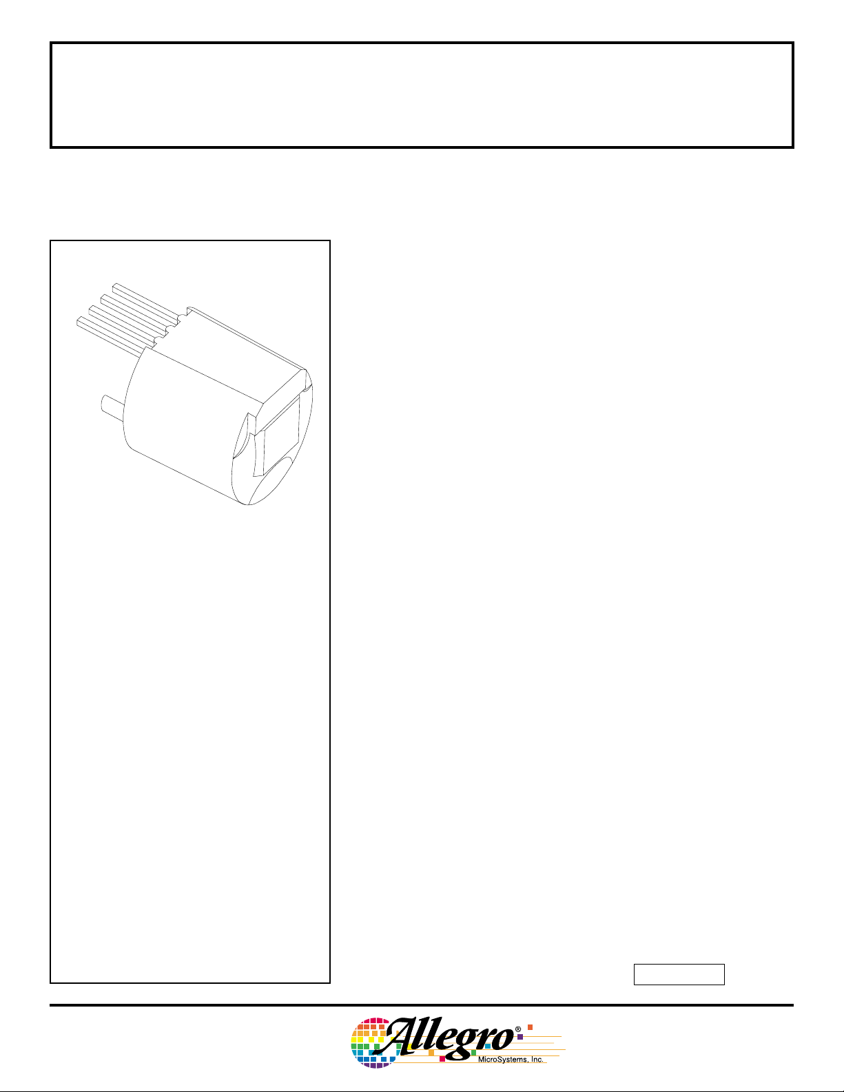
HALL-EFFECT
GEAR-TOOTH SENSOR
SUBASSEMBLY
NON-ORIENTED, HALL-EFFECT GEAR-TOOTH SENSOR
1
2
3
4
Pin 1 = Supply
Pin 2 = Output
Pin 3 = Test Point
Pin 4 = Ground
PRELIMINARY INFORMATION
(subject to change without notice)
December 2, 1998
Dwg. AH-006-2
ATS632LSA
ZERO-SPEED, SELF-CALIBRATING,
The ATS632LSA gear-tooth sensor is an optimized Hall-effect IC/
magnet combination that provides extremely accurate tooth edge
detection when used with large-pitch targets. The sensor subassembly
consists of a high-temperature plastic shell that holds together a
compound samarium-cobalt magnet and a single-element self-calibrating Hall-effect IC that has been optimized to the magnetic circuit. This
small package, with its non-oriented operation, can be easily assembled on a PC board for complete protection and used in conjunction with a number of gear configurations.
The gear sensing technology used for this sensor subassembly is
Hall-effect based. The sensor incorporates a single-element Hall IC
that switches in response to absolute magnetic signals created by a
ferrous target. The digital output is LOW over a tooth and HIGH over a
valley. The sophisticated processing circuitry contains self-calibrating
6-bit A/D circuitry that adapts the thresholds to the peak-to-peak
signals to minimize the effects of variation in application air gap on
switch-point timing accuracy. The effects of system and device offsets
are minimized by using active offset cancellation circuitry. The digital
algorithm provides zero-speed detection capabilities without the
associated running jitter inherent in classical digital solutions.
Data Sheet
27627.125
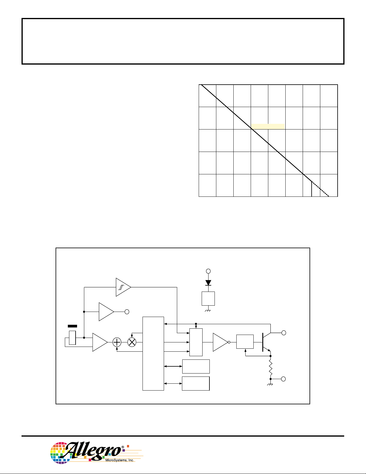
ABSOLUTE MAXIMUM RATINGS
Supply Voltage, VCC.........................24 V*
Reverse Supply Voltage, V
Output OFF Voltage, V
Output Current, I
Reverse Output Current, I
Package Power Dissipation,
.................................... See Graph
P
D
Operating Temperature Range,
............................ -40°C to +150°C
T
A
Storage Temperature, TS............ +170°C
* Operation at increased supply voltages with
external circuitry is described in Applications
Information.
OUT
.. Internally Limited
OUT
........ -24 V
RCC
................. 25 V
........ 50 mA
OUT
This sensor system is ideal for use in gathering speed, position
and profile information of ferrous objects. They are particularly suited
to large tooth/valley sensing applications where accurate timing
accuracy is a desired feature. For applications requiring the sensing of
fine-pitch gears, the ATS610LSA and ATS611LSB are recommended.
continued next page…
Always order by complete part number, e.g., ATS632LSA .
Page 2
ATS632LSA
ALLOWABLE PACKAGE POWER DISSIPATION IN mW
HALL-EFFECT
GEAR-TOOTH SENSOR
SUBASSEMBLY
FEATURES AND BENEFITS
■ Non-Oriented Installation
■ Fully Optimized Gear-Tooth Sensors
■ Zero-Speed Digital Output Representing Target
Profile
■ Large Operating Air Gaps
■ Extremely Low Timing Accuracy Drift with Tempera-
ture
■ Correct First-Edge Detection
■ Self-Calibrating Circuitry
with Integrated Offset Cancellation
6-bit A/D Converters to Capture Peaks
Thresholds Proportional to Peak-to-Peak Signals
■ Optimized Magnetic Circuit
■ Single-Chip Sensing IC for High Reliability
1000
800
600
400
200
RθJA = 147°C/W
0
40 80 120
60 100 140 18020
AMBIENT TEMPERATURE IN °C
160
Dwg. GH-065-1
MAGNET
X
FUNCTIONAL BLOCK DIAGRAM
SUPPLY
1
POWER ON
REG
TEST
3
POINT
GAIN
–
+
OFFSET
REFERENCE
GENERATOR
THRESHOLD
PEAK
LOGIC
OUTPUT
POSITIVE PEAK
TRACK & HOLD
NEGATIVE PEAK
TRACK & HOLD
CURRENT
LIMIT
2
OUTPUT
4
GROUND
Dwg. FH-015-2
115 Northeast Cutoff, Box 15036
Worcester, Massachusetts 01615-0036 (508) 853-5000
W
Copyright © 1998, Allegro MicroSystems, Inc.
Page 3

ATS632LSA
HALL-EFFECT
GEAR-TOOTH SENSOR
SUBASSEMBLY
ELECTRICAL CHARACTERISTICS over operating voltage and temperature range (unless
otherwise specified).
Limits
Characteristic Symbol Test Conditions Min. Typ. Max. Units
Supply Voltage V
Under-Voltage Lockout V
Low Output Voltage V
Output Current Limit I
Output Leakage Current I
Supply Current I
Calibration Count n
CC
CC(UV)
OUT(L)
OUTM
OFF
CC
cal
Operating, TJ < 165°C 4.5 – 24 V
I
= 20 mA, VCC = 0 → 5 V – 4.0 – V
OUT
I
= 20 mA, Output ON – 0.2 0.4 V
OUT
V
= 12 V 25 45 55 mA
OUT
V
= 24 V, Output OFF – 0.2 5.0 µA
OUT
Output OFF, Target Speed = 0 RPM – 9.0 15 mA
Output falling mechanical edges 16 16 16 Pulses
after power on for startup calibration
to be complete
Calibration Update n
up
Output falling mechanical edges 64 64 64 Pulses
for the threshold calibration to be
complete
Power-On Time t
Output Rise Time t
Output Fall Time t
NOTE: Typical data is at VCC = 12 V and TA = +25°C and is for design information only.
po
r
f
VCC > 4.5 V – 80 500 µs
RL = 500 Ω, CL = 10 pF – 0.2 5.0 µs
RL = 500 Ω, CL = 10 pF – 0.2 5.0 µs
Page 4

ATS632LSA
HALL-EFFECT
GEAR-TOOTH SENSOR
SUBASSEMBLY
OPERATION over operating voltage and temperature range with reference target (unless otherwise specified).
Limits
Characteristic Symbol Test Conditions Min. Typ. Max. Units
Operating Air Gap Range AG Operating, 0.3 – 2.5 mm
Target Speed > 20 RPM
Output Polarity – Operating, Over Tooth Low Low Low –
Operating, Over Valley High High High –
Timing Accuracy t
θ
Target Speed < 3500 RPM, – ±0.25 ±0.50 °
0.3 mm ≤ AG ≤ 2.0 mm
TARGET DESIGN CRITERIA
Limits
Characteristic Symbol Description Min. Typ. Max. Units
Valley Depth h
Valley Width (P
Tooth Width T – 5.0 – mm
Thickness F – 5.0 – mm
Eccentricity – Timing accuracy may change ––±0.25 mm
t
- T) – 5.0 – mm
C
– 5.0 – mm
TARGET DIMENSIONS
Diameter Thickness Tooth Width Valley Width Valley Depth
Type (D
Reference Target 84 mm 16 mm 9 mm 13 mm 5 mm
Characterization Target #1 84 mm 16 mm 1 tooth, 180° 5 mm
Characterization Target #2 35 mm 7 mm 1 tooth, 180° 6 mm
NOTE: Timing accuracy data is taken by recalibrating the unit at each air gap.
) (F) (T) (PC - T) (ht)
o
115 Northeast Cutoff, Box 15036
Worcester, Massachusetts 01615-0036 (508) 853-5000
Page 5

ATS632LSA
HALL-EFFECT
GEAR-TOOTH SENSOR
SUBASSEMBLY
TYPICAL OPERATING CHARACTERISTICS
3.0
2.0
1.0
0
-1.0
-2.0
TARGET #1
-40°C
+25°C
+150°C
RISING EDGE
RELATIVE TIMING ACCURACY IN DEGREES
-3.0
0.5 1.5 2.25
0.75 1.25 1.75
1.0
AIR GAP IN MILLIMETERS
2.0
Dwg. GH-063
3.0
TARGET #1
2.0
1.0
0
-1.0
-2.0
-40°C
+25°C
+150°C
FALLING EDGE
RELATIVE TIMING ACCURACY IN DEGREES
-3.0
0.5 1.5 2.25
0.75 1.25 1.75
1.0
AIR GAP IN MILLIMETERS
2.0
Dwg. GH-063-1
3.0
TARGET #2
2.0
1.0
0
-1.0
-2.0
-40°C
+25°C
+150°C
RISING EDGE
RELATIVE TIMING ACCURACY IN DEGREES
-3.0
0.5 1.5 2.25
0.75 1.25 1.75
1.0
AIR GAP IN MILLIMETERS
2.0
Dwg. GH-063-2
3.0
TARGET #2
2.0
1.0
0
-1.0
-2.0
-40°C
+25°C
+150°C
FALLING EDGE
RELATIVE TIMING ACCURACY IN DEGREES
-3.0
0.5 1.5 2.25
0.75 1.25 1.75
1.0
AIR GAP IN MILLIMETERS
continued next page…
2.0
Dwg. GH-063-3
Page 6

ATS632LSA
HALL-EFFECT
GEAR-TOOTH SENSOR
SUBASSEMBLY
TYPICAL OPERATING CHARACTERISTICS — Continued
51.0
TARGET #1
50.5
50.0
49.5
49.0
-40°C
+25°C
+150°C
DUTY CYCLE IN PER CENT
48.5
48.0
0.5 1.5 2.25
0.75 1.25 1.75
1.0
AIR GAP IN MILLIMETERS
2.0
Dwg. GH-008-3
51.0
TARGET #2
50.5
50.0
49.5
49.0
-40°C
+25°C
+150°C
DUTY CYCLE IN PER CENT
48.5
48.0
0.75 1.25 1.75
0.5 1.5 2.25
1.0
AIR GAP IN MILLIMETERS
2.0
Dwg. GH-008-4
+3
+2
+1
0
RISING EDGE
-1
-2
RELATIVE TIMING ACCURACY IN DEGREES
-3
0
AIR GAPS
0.5 mm
1.0 mm
1.5 mm
2.0 mm
2.5 mm
1000 3000 5000 70002000 4000 6000
REFERENCE TARGET SPEED IN RPM
+3
+2
+1
0
FALLING EDGE
Dwg. GH-064-1
-1
-2
RELATIVE TIMING ACCURACY IN DEGREES
-3
0
AIR GAPS
0.5 mm
1.0 mm
1.5 mm
2.0 mm
2.5 mm
1000 3000 5000 70002000 4000 6000
REFERENCE TARGET SPEED IN RPM
115 Northeast Cutoff, Box 15036
Worcester, Massachusetts 01615-0036 (508) 853-5000
Dwg. GH-064-2
Page 7

ATS632LSA
HALL-EFFECT
GEAR-TOOTH SENSOR
SUBASSEMBLY
CRITERIA FOR DEVICE QUALIFICATION
All Allegro sensors are subjected to stringent qualification requirements prior to being released to production. To
become qualified, except for the destructive ESD tests, no failures are permitted.
Test Method and Samples
Qualification Test Test Conditions Test Length Per Lot Comments
Temperature Humidity JESD22-A101, 1000 hrs 48 Device biased for
Bias Life TA = 85°C, RH = 85% minimum power
Bias Life JESD22-A108, 1000 hrs 48
TA = 150°C, TJ = 165°C
(Surge Operating Life) JESD22-A108, 168 hrs 48
TA = 175°C, TJ = 190°C
Autoclave, Unbiased JESD22-A102, 96 hrs 48
TA = 121°C, 15 psig
High-Temperature JESD22-A103, 1000 hrs 48
(Bake) Storage Life TA = 170°C
Temperature Cycle JESD22-A104 1000 cycles 48 -55°C to +150°C
ESD, CDF-AEC-Q100-002 Pre/Post 3 per Test to failure
Human Body Model Reading test Pin 3 > 1.5 kV
All leads > 8 kV
APPLICATIONS INFORMATION
Recommended Evaluation Technique. The selfcalibrating feature of the ATS632LSA requires that a
special evaluation technique be used to measure its highaccuracy performance capabilities. Installation inaccuracies are calibrated out at power on; hence, it is extremely
important that the device be re-powered at each air gap
when gathering timing accuracy data.
Self-Calibrating Functions. These subassemblies are
designed to minimize performance variation caused by
the large air gap variations resulting from installation by
self-calibrating at power-on. They are also designed to
minimize performance variation caused by the smaller,
slower air gap changes resulting from temperature
change and gear run-out during continuous operation by
updating the self-calibration periodically (after every 64
output pulses) if necessary. These two functions should
be tested using the following procedure.
1. Set the air gap to the desired value.
2. Power down and then power on the device.
3. Rotate the target at the desired speed.
4. Wait for calibration to complete (16 output pulses to
occur).
5. Monitor output for correct switching and measure
accuracy.
6. Repeat the above for multiple air gaps within the
operating range of the device.
7. This can be repeated over the entire temperature
range.
Page 8

ATS632LSA
HALL-EFFECT
GEAR-TOOTH SENSOR
SUBASSEMBLY
APPLICATIONS INFORMATION — Continued
Measurement of the effect of changing air gap after power
on:
1. Set the air gap to the desired value (nominal, for
example). Rotate the target at the desired speed.
Apply power to the subassembly. Wait for 16 output
pulses to occur. Monitor output for correct switching
and measure accuracy.
2. Change the air gap by ± 0.25 mm. Do not re-power
subassembly. Wait for 64 output pulses to occur.
Monitor the output for correct switching and measure
accuracy.
Device Switch Points. The device switch points are
referenced to the peak-to-peak values of the gain-adjusted signal. The comparator thresholds have been
chosen to provide timing accuracy, as well as limited
immunity from mis-detection caused by short valley
conditions or by gear run-out.
Gear Design Criteria.* The system was designed to
work correctly with minimum valley depths of 5 mm and
minimum valley widths of 13 mm. As the valley depth
decreases, the valley field rises above the open-circuit
value of the magnetic circuit when the sensor is at minimum air gap. The same is true when the valley width
decreases. In both cases, the metal mass from the valley
bottom or side walls provides an interference at minimum
air gap and will provide a signal that may be interpreted
as a tooth upon power on. It is important to note that this
anomaly will normally only affect the power-on state of the
device and the self-calibration circuitry will null this
baseline shift when the device is in running mode.
* In application, the terms “gear” and “target” are often
interchanged. However, “gear” is preferred when motion
is transferred.
Operation with Fine-Pitch Gears. The self-calibration
routines allow the detection of fine-pitch gears once the
target is rotating. The major issue in these applications is
the impact of gear run-out on the baseline of the magnetic
field. Excessive run-out may result in tooth edges not
being detected.
Signal Duty Cycle. For regular tooth geometries, precise
duty cycle is maintained over the operating air gap and
temperature range due to the good symmetry of the
magnetic switch points of the device.
Output. The output of the subassembly is a short-circuitprotected open-collector stage capable of sinking 20 mA.
An external pull-up (resistor) to a supply voltage of not
more than 24 V must be supplied.
Output Polarity. The switching of the output is independent of the direction of gear rotation.
Power Supply Protection. The device contains an onchip regulator and can operate over a wide supply voltage
range (4.5 V to 24 V). For devices that need to operate
from an unregulated power supply, transient protection
must be added externally. For applications being run off a
regulated line, EMI/RFI protection is still required. Incorrect protection can result in unexplained pulses on the
output line, providing inaccurate sensing information to
the user.
Signal-Timing Accuracy. Timing accuracy is improved
with larger gear diameters. The magnetic field profile has
a defined spread that narrows in degrees as the target
diameter increases. The slope of this magnetic profile
also changes with air gap. For highest accuracy, targets
greater than 100 mm diameter should be used.
115 Northeast Cutoff, Box 15036
Worcester, Massachusetts 01615-0036 (508) 853-5000
continued next page…
Page 9

ATS632LSA
HALL-EFFECT
GEAR-TOOTH SENSOR
SUBASSEMBLY
APPLICATIONS INFORMATION — Continued
The protection circuitry can easily be added to a PC
board for use with this device. Provisions have been
made for easy mounting of a PC board on the back of the
unit. PC board installation parallel to the device axis is
also possible.
4
3
2
1
Dwg. AH-007
Operation From a Regulated Power Supply. These
devices require minimal protection circuitry during operation from a low-voltage regulated line. The on-chip
voltage regulator provides immunity to power supply
variations between 4.5 V and 24 V. However, even while
operating from a regulated line, some supply and output
filtering is required to provide immunity to coupled and
injected noise on the supply line. A basic RC low-pass
filter circuit (R1C1) on the supply line and an optional
output capacitor (C2) is recommended for operation in
noisy environments. In extremely noisy environments, a
filter capacitor at pin 3 may also be required. Because the
device has an open collector output, an output pull-up
resistor must be added either at the sensor module or at
the controller.
SUPPLY
20 Ω
R
L
C
R
1
1
0.033 µF
OUTPUT
100 pF
100 pF
C
C
2
3
12
Vcc
4
3
X
Dwg. EH-008-3A
continued next page…
Page 10

ATS632LSA
HALL-EFFECT
GEAR-TOOTH SENSOR
SUBASSEMBLY
APPLICATIONS INFORMATION — Continued
Operation from an Unregulated Power Supply. In
applications where the device gets its power from an
unregulated supply such as an automotive battery, full
protection is generally required. In addition to supply
regulation, such applications require the device to withstand various supply side transients. Specifications for
such transients vary between car manufacturers and
protection circuit design should be optimized for each
application. In the circuit shown below, a simple Zenercontrolled regulator is constructed using discrete components. The RC low-pass filter on the supply line (R1C1)
and a low-value supply bypass capacitor (CS) can be
included, if necessary, so as to minimize the susceptibility
to EMI/RFI. The NPN should be chosen with sufficiently
high forward breakdown voltage so as to hold off supplyside transients. The series diode should be chosen with
sufficiently high reverse breakdown capabilities so as to
withstand the most negative transient. The current-limiting
resistor (RZ) and the Zener diode should be sized for
power dissipation requirements.
SUPPLY
2.5 kΩ
0.1 µF
C
S
R
L
20 Ω
R
1
R
Z
6.8 V
C
1
0.033 µF
Vcc
OUTPUT
X
312
100 pF
100 pF
C
C
2
3
4
Dwg. EH-008-2A
Additional applications Information on gear-tooth and
other Hall-effect sensors is provided in the Allegro Inte-
grated and Discrete Semiconductors Data Book or
Application Note 27701.
115 Northeast Cutoff, Box 15036
Worcester, Massachusetts 01615-0036 (508) 853-5000
Page 11

ATS632LSA
HALL-EFFECT
GEAR-TOOTH SENSOR
SUBASSEMBLY
MECHANICAL INFORMATION
Component Material Function Units
Sensor Face Thermoset epoxy Maximum temperature 170 °C*
Plastic Housing Polyamide, 33% glass filled 264 psi deflection temp. (DTUL) 225°C
(Nylon 6, 6)
Leads Copper ––
Lead Pull –– 8 N
Lead Finish 90/10 tin/lead solder plate –†
Flame Class Rating –– UL94V-0
*Temperature excursions to 225 °C for 2 minutes or less are permitted.
†All industry-accepted soldering techniques are permitted for these subassemblies provided the indicated
maximum temperature for each component (e.g., sensor face, plastic housing) is not exceeded. Reasonable
dwell times, which do not cause melting of the plastic housing, should be used.
Sensor Location (in millimeters)
(sensor location relative to package center is the design
objective)
Approximate melting temperature 260°C
Lead Cross-Section (in millimeters)
0.1
A
Dwg. MH-018-2 mm
0.41
0.38
0.0076
MIN. PLATING
THICKNESS
Dwg. MH-019 mm
continued next page…
Page 12

ATS632LSA
HALL-EFFECT
GEAR-TOOTH SENSOR
SUBASSEMBLY
DIMENSIONS IN MILLIMETERS
3.0
NOM
0.38
1.27
TYP
1 2 3 4
8.3
8.0
SEE NOTE
0.41
0.9
7.25
5.00
DIA
2.0
9.0
3.9
Tolerances unless otherwise specified:1 place ±0.1 mm, 2 places ±0.05 mm.
NOTE — Nominal dimension and tolerances dependent on package material. Contact factory.
A
9.0
Dwg. MH-017A mm
Allegro MicroSystems, Inc. reserves the right to make, from time to
time, such departures from the detail specifications as may be required
to permit improvements in the design of its products.
The information included herein is believed to be accurate and
reliable. However, Allegro MicroSystems, Inc. assumes no responsibility for its use; nor for any infringements of patents or other rights of third
parties which may result from its use.
115 Northeast Cutoff, Box 15036
Worcester, Massachusetts 01615-0036 (508) 853-5000
 Loading...