

Page 1
PD - 94550
A TR28XXD SERIES
ADVANCED ANALOG
HYBRID-HIGH RELIABILITY
DC/DC CONVERTERS
Description
The ATR28XXD Series of DC/DC converters feature
high power density and an extended temperature range
for use in military and industrial applications. Designed
to MIL-STD-704D input requirements, these devices
have nominal 28VDC inputs with ±12V and ±15V dual
outputs to satisfy a wide range of requirements. The
circuit design incorporates a pulse width modulated
single forward topology operating in the feed-forward
mode at a nominal switching frequency of 550KHz.
Input to output isolation is achieved through the use of
transformers in the forward and feedback circuits.
The advanced feedback design provides fast loop response for superior line and load transient characteristics and offers greater reliability and radiation tolerance than devices incorporating optical feedback circuits.
Three standard temperature grades are offered with
screening options. Ref er to P art Number section. The y
can be provided in a standard plug-in package for PC
mounting or in a flanged package for more severe environments.
These converters are manufactured in a facility certified to MIL-PRF-38534. All processes used to manufacture these converters have been qualified to enable
Advanced Analog to deliver compliant devices.
28V Input, Dual Output
ATR
Features
n 16 to 40 VDC Input Range (28 VDC Nominal)
n
±12V and ±15V Outputs Available
n Indefinite Short Circuit and Overload
Protection
n 35 W/in
n 30 Watt Output Power
n Fast Loop Response for Superior Transient
Characteristics
n Operating Temperature Range from -55°C to
+125°C
n Popular Industry Standard Pin-Out
n Resistance Seam Welded Case for Superior
Long Term Hermeticity
n Ceramic Feed-thru Pins
n External Synchronization
n High Efficiency
n Shutdown from External Signal
n Military Screening
3
Power Density
Four screening grades are available to satisfy a wide
range of requirements. The CH grade converters are
fully compliant to MIL-PRF-38534 for class H. The HB
grade converters are processed to full class H screening but do not have class H element evaluation as required by MIL-PRF-38534. Both grades are fully tested
and operate over the full military temperature range
without derating of output power. The ES version is a
full temperature device without the full class H or element evaluation. The non-suffix device is a low cost
limited temperature range option. Variations in
electrical, mechanical and screening can be accommodated.
Extensive computer simulation using complex
modeling enables rapid design modification to
be provided. Contact Advanced Analog with specific requirements.
www.irf.com 1
10/29/02
Page 2
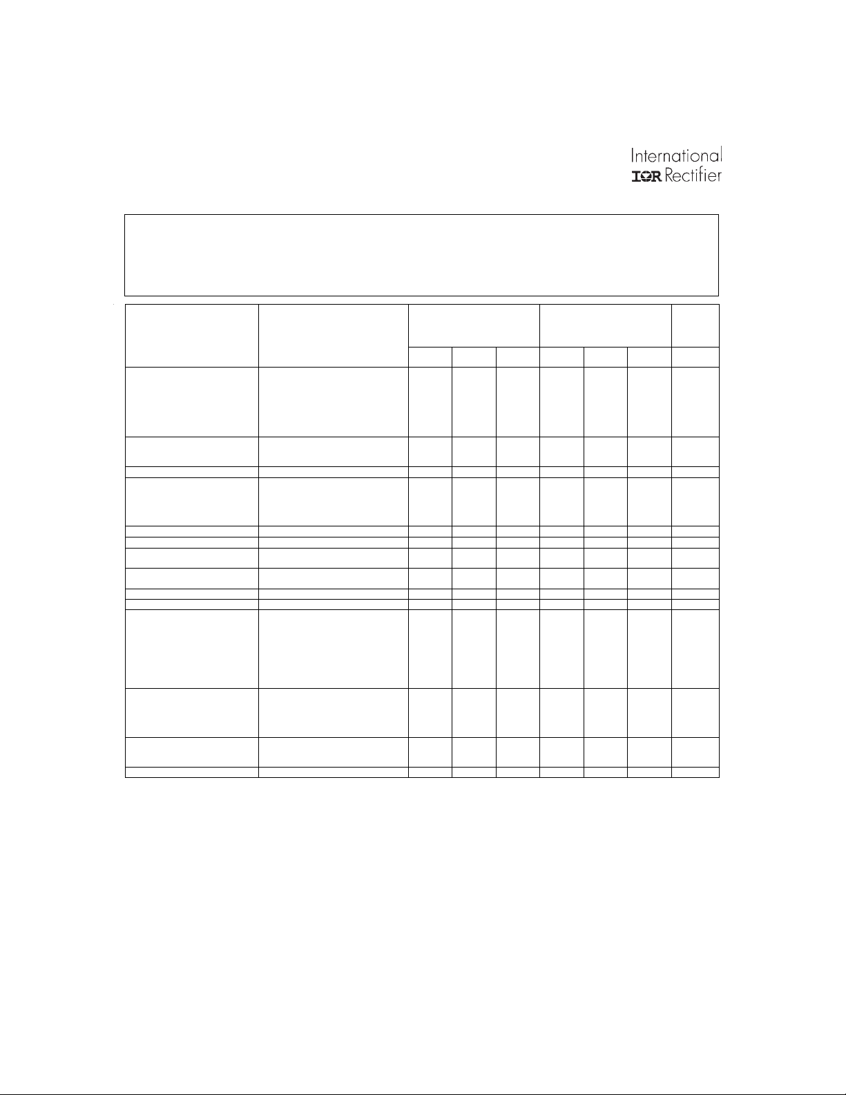
ATR28XXD Series
Specifications
T
= -55°C to +85°C, V
CASE
ABSOLUTE MAXIMUM RATINGS
Input Voltag e - 0 . 5 V to 50V D C
Power Output Interna lly limited, 36W ty p ical
Solde ring 300°C for 10 seconds
Temperature Range
1
R e c o mme n ded Operating -55°C to +8 5 °C
Maximum Operating -5 5°C to +11 5 °C
S to r a ge -6 5°C to +135°C
PARAMETER
STATIC CHARACTERISTICS
OUTPUT VIN = 16 to 40 VDC
Voltage I
Current 5 0.0
Ripple Full Load, 20KHz to 2MHz 40 85 40 85 mV p-p
Accuracy
Power1 30 30 W
REGULATION
Line
Load
CROSS REGULATION6 V
INPUT
Voltage Range
Current
Ripple Current
EFFICIENCY
ISOLATION Input to output @500 VDC 100 100
CAPACITIVE LOAD No effect on performance
Load Fault Power Dissipation Short Circuit
Switching Frequency I
SYNC Frequency Range7 500 700 500 700 KHz
DYNAMIC CHARACTERISTICS
Step Load Changes
Output
Transient
Recovery 2
Step Line Changes
Output
Transient
Recovery 2
TURN-ON
Overshoot
Delay3
Load Fault Recovery VIN = 16 to 40 VDC 14 25 14 25 ms
Notes to Specifications
1. Above +85°C case temperature, derate output power linearly to 0 at +115°C case.
2. Recovery time is measured from the initiation of the input transient to where V
3. Turn-on delay time measurement is for either an application of power at the input or a signal at the inhibit pin.
4. Load current split equally between +V
5. Up to 90% of Full Power is available from either output provided. The total power output does not exceed 30 watts.
6. 3W load on output under test, 3W to 27W on other output.
7. Sync. Input signal: V
0.8V Max 11.5V Max
= -0.5V Min, V
IL
= +28V ± 5% unless otherwise specified
IN
-55°C ≤ TC ≤ +85°C, V
OUT
T
CASE
VIN = 16 to 40 VDC
I
OUT
IN
No Load, pin 2 = open
Inhibited, pin 2 tied to pin 10
Full Load
Full Load TC = +25°C
TC = +25°C (total for both outputs)
Overload, TC = +25°C
OUT
50% Load to 100% Load
No Load to 50% Load
50% Load to 100% Load
No Load to 50% Load
50% Load to No Load
Input step 16 to 40 VDC
Input step 40 to 16 VDC
Input step 16 to 40 VDC
Input step 40 to 16 VDC
VIN = 16 to 40 VDC
I
OUT
Condition
±
5%, CL=0, unless otherwise
specified
= 0 to Full Load
= 25°C, Full Load
= 0 to Full Load
= 16, 28, and 40 VDC
= Full Load 500 600 500 600 KHz
= O and Full Load
and –V
OUT
= 2.5V Min, 10% to 90% duty cycle,
IN
OUT
= 28 V
IN
.
DC
Min Typ Max Min Typ Max Units
±
11.76 ±12.00 ±12.24 ±14.70 ±15.00 ±15.30
±
11.88 ±12.00 ±12.12 ±14.85 ±15.00 ±15.15
16.0 28.0
82 82 %
100 100
9
ATR2812D
±
1.25
75
120
±
5
40.0
75
25
±
100
±
250
25
500
3
±
180
-600
5
5
0
14
18
50
14
600
25
has returned to within ±1% of V
OUT
0.0
16.0 28.0
9
ATR2815D
25
±
100
±
250
25
500
3
±
180
-600
5
5
0
14
VDC
ADC
VDC
mV
mV
%
5
mVpk
VDC
mADC
mADC
mA p-p
MΩ
µ
F
W
W
mVpk
µ
s
µ
s
ms
mVpk
mVpk
ms
ms
mVpk
ms
at 50% load.
OUT
±
1.0
75
150
±
40.0
75
18
50
14
600
25
2 www.irf.com
Page 3
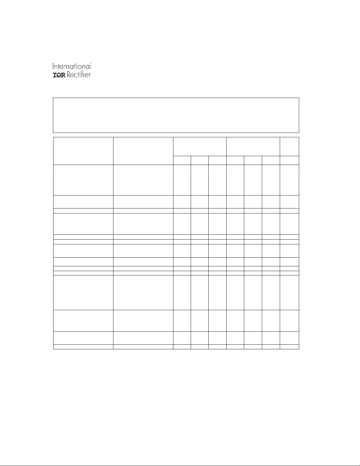
ATR28XXD Series
Specifications
T
= -55°C to +125°C, V
CASE
ABSOLUTE MAXIMUM RATINGS
Input Voltage -0.5V to 50VDC
Power Output Internally limited, 36W typical
Soldering 300°C for 10 seconds
Temperature Range
1
Recommend ed O pe rating -55°C to +125°C
Maximum Operating -55°C to +135°C
Storage -65°C to +13 5°C
STATIC CHARACTERISTICS
OUTPUT VIN = 16 to 40 VDC
Voltage I
Current 5 0.0
Ripple Full Load, 20KHz to 2MHz 40 85 40 85 mV p-p
Accuracy
Power1 30 30 W
REGULATION
Line
Load
CROSS REGULATION6 V
INPUT
Voltage Range
Current
Ripple Current
EFFICIENCY
ISOLATION Input to output @500 VDC 100 100
CAPACITIVE LOAD No effect on perfor m ance
Load Fault Power Dissip at ion Short Circuit
Switching Frequency I
SYNC Frequency Range7 500 700 500 700 KHz
DYNAMIC CHARACTERISTICS
Step Load Changes
Output
Transient
Recovery
Step Line Changes
Output
Transient
Recovery
TURN-ON
Overshoot
Delay3
Load Fault Recovery VIN = 16 to 40 VDC 14 25 14 25 ms
Notes to Specifications
PARAMETER
2
2
1. Above +125°C case temperature, derate output power linearly to 0 at +135°C case.
2. Recovery time is measured from the initiation of the input transient to where V
3. Turn-on delay time measurement is for either an application of power at the input or a signal at the inhibit pin.
4. Load current split equally between +V
5. Up to 90% of Full Power is available from either output provided. The total power output does not exceed 30 watts.
6. 3W load on output under test, 3W to 27W on other output.
7. Sync. Input signal: V
0.8V Max, 11.5V Max
= -0.5V Min, V
IL
= +28V ± 5% unless otherwise specified
IN
Condition
-55°C ≤ TC ≤ +125°C, V
V
±5%, CL=0, unless otherwise
DC
specified
= 0 to Full Load
OUT
T
= 25°C, Full Load
CASE
= 16 to 40 VDC
V
IN
I
= 0 to Full Load
OUT
= 16, 28, and 40 VDC
IN
No Load, pin 2 = open
Inhibited, pin 2 tied to pin 10
Full Load
Full Load T
T
C
outputs)
Overload, T
OUT
50% Load to
No Load to 50% Load
50% Load to 100% Load
No Load to 50% Load
50% Load to No Load
Input step 16 to 40
Input step 40 to 16 V
Input step 16 to 40 VDC
Input step 40 to 16 VDC
V
IN
I
OUT
= +25°C
C
= +25°C (total for both
= +25°C
C
= Full Load 500 600 500 600 KHz
100% Load
= 16 to 40 VDC
= O to Full Load
and –V
OUT
= 2.5V Min, 10% to 90% duty cycle
IN
VDC
OUT
= 28
IN
Min Typ Max Min Typ Max Units
±
11.76 ±12.00 ±12.24 ±14.70 ±15.00 ±15.30
±
11.88 ±12.00 ±12.12 ±14.85 ±15.00 ±15.15
16.0 28.0
80 82 79 82 %
100 100
9
DC
.
ATR2812D/ES
25
±
100
±
250
25
500
3
±
180
-600
5
5
0
14
OUT
75
±
75
18
50
14
5
0.0
16.0 28.0
9
±
1.25
120
40.0
600
25
has returned to within ±1% of V
ATR2815D/ES
25
±
100
±
250
25
500
3
±
180
-600
5
5
0
14
±
1.0
75
150
±
5
40.0
75
18
50
14
mVpk
600
25
at 50% load.
OUT
VDC
A
DC
V
DC
mV
mV
%
V
DC
mA
DC
mA
DC
mA p-p
MΩ
µ
F
W
W
mVpk
µ
s
µ
s
ms
mVpk
mVpk
ms
ms
mVpk
ms
www.irf.com 3
Page 4

ATR28XXD Series
Specifications
T
= -55°C to +125°C, V
CASE
ABSOLUTE MAXIMUM RATINGS
Input Voltage -0.5V to 50VDC
Power Output In ternally limited, 36W typical
Soldering 300°C for 10 seconds
Temperature Range
1
Recommended Operating -55°C to +125°C
Maximum Op erating -55°C to +135°C
Storage -65°C to +135 °C
PARAMETER
STATIC CHARACTERISTICS
OUTPUT VIN = 16 to 40 VDC
Voltage I
Current 5 0.0
Ripple Full Load, 20KHz to 2MHz 40 85 40 85 mV p-p
Accuracy
Power1 30 30 W
REGULATION
4
Line
4
Load
CROSS REGULAT IO N6 V
INPUT
Voltage Range
Current
Ripple Current
EFFICIENCY
ISOLATION Input to output @500 VDC 100 100
CAPACITIVE LOAD No effect on performance
Load Fault Power Dissipation Short Circuit
Switching Frequency I
SYNC Frequency Range7 500 700 500 700 KHz
DYNAMIC CHARACTERISTICS
Step Load Changes
Output4
Transient
Recovery
Step Line Changes
Output
Transient
Recovery
TURN-ON
Delay3
Load Fault Recovery VIN = 16 to 40 VDC 14 25 14 25 ms
Overshoot
2
2
Notes to Specifications
1. Above +125°C case temperature, derate output power linearly to 0 at +135°C case.
2. Recovery time is measured from the initiation of the input transient to where V
3. Turn-on delay time measurement is for either an application of power at the input or a signal at the inhibit pin.
4. Load current split equally between +V
5. Up to 90% of Full Power is available from either output provided. The total power output does not exceed 30 watts.
6. 3W load on output under test, 3W to 27W on other output.
7. Sync. Input signal: V
0.8V Max, 11.5V Max
= -0.5V Min, V
IL
= +28V ± 5% unless otherwise specified
IN
-55°C ≤ TC ≤ +125°C, V
OUT
T
CASE
V
IN
I
OUT
IN
No Load, pin 2 = open
Inhibited, pin 2 tied to pin 10
Full Load
Full Load T
= +25°C (total for both outputs)
T
C
Overload, T
OUT
50% Load to
No Load to 50% Load
50% Load to 100% Load
No Load to 50% Load
50% Load to No Load
Input step 16 to 40
Input step 40 to 16 V
Input step 16 to 40 VDC
Input step 40 to 16 VDC
V
IN
I
OUT
Condition
±5%, CL=0, unless otherwise
specified
= 0 to Full Load
= 25°C, Full Load
= 16 to 40 VDC
= 0 to Full Load
= 16, 28, and 40 VDC
= 28 VDC
IN
Min Typ Max Min Typ Max Units
±
11.76 ±12.00 ±12.24 ±14.70 ±15.00 ±15.30
±
11.88 ±12.00 ±12.12 ±14.85 ±15.00 ±15.15
16.0 28.0
= +25°C
C
= +25°C
C
= Full Load 500 600 500 600 KHz
100% Load
VDC
DC
= 16 to 40 VDC
= O to Full Load
and –V
OUT
= 2.5V Min, 10% to 90% duty cycle
IN
OUT
.
80 82 79 82 %
ATR2812D/HB
75
±
75
18
50
5
0.0
16.0 28.0
±
1.25
120
25
40.0
100 100
9
±
±
500
±180
-600
14
±
100
450
±
250
760
25
70
1500
3
5
1200
-1500
10
5
10
5
0
600
14
25
has returned to within ±1% of V
OUT
9
ATR2815D/HB
18
25
±
100
±
250
25
500
3
±180
-600
5
5
0
14
±
1.0
75
150
±
5
40.0
75
18
50
14
±
450
±
750
70
1500
5
1500
-1500
10
10
600
25
at 50% load.
OUT
V
DC
ADC
V
DC
mV
mV
%
V
DC
mA
mA
mA p-p
MΩ
µ
F
W
W
mVpk
mVpk
µs
µ
s
ms
mVpk
mVpk
ms
ms
mVpk
ms
DC
DC
4 www.irf.com
Page 5

ATR28XXD Series
Specifications
T
= -55°C to +125°C, V
CASE
= +28V ± 5% unless otherwise specified
IN
ABSOLUTE MAXIMUM RATINGS
Input Voltage -0.5V to 50VDC
Power Output Internally limited, 36W typical
Soldering 300°C for 10 seconds
Temperature Range
1
Recommended Operating -55°C to +125°C
Maximum Operating -55°C to +135°C
Storage -65°C to +135°C
PARAMETER
STATIC CHARACTERISTICS
OUTPUT VIN = 16 to 40 VDC
Voltage I
Current 5 0.0
Ripple Full Load, 20KHz to 2MHz 40 85 40 85 mV p-p
Accuracy
Power1 30 30 W
REGULATION
4
Line
4
Load
CROSS REGULATIO N6 V
INPUT
Voltage Range
Current
Ripple Current
EFFICIENCY
ISOLATION Input to output @500 VDC 100 100
CAPACITIVE LOAD No effect on performance
Load Fault Power Dissipation Short Circuit
Switching Frequency I
SYNC Frequency Range7 500 700 500 700 KHz
DYNAMIC CHARACTERISTICS
Step Load Changes
Output4
Transient
Recovery
Step Line Changes
Output
Transient
Recovery
TURN-ON
Delay3
Load Fault Recovery VIN = 16 to 40 VDC 14 25 14 25 ms
Overshoot
2
2
-55°C ≤ TC ≤ +125°C, V
OUT
T
CASE
V
IN
I
OUT
IN
No Load, pin 2 = open
Inhibited, pin 2 tied to pin 10
Full Load
Full Load T
= +25°C (total for both outputs)
T
C
Overload, T
OUT
50% Load to
No Load to 50% Load
50% Load to 100% Load
No Load to 50% Load
50% Load to No Load
Input step 16 to 40
Input step 40 to 16 V
Input step 16 to 40 VDC
Input step 40 to 16 VDC
V
IN
I
OUT
Condition
±
5%, CL=0, unless otherwise
specified
= 0 to Full Load
= 25°C, Full Load
= 16 to 40 VDC
= 0 to Full Load
= 16, 28, and 40 VDC
= 28 VDC
IN
Min Typ Max Min Typ Max Units
±
11.76 ±12.00 ±12.24 ±14.70 ±15.00 ±15.30
±
11.88 ±12.00 ±12.12 ±14.85 ±15.00 ±15.15
16.0 28.0
= +25°C
C
= +25°C
C
= Full Load 500 600 500 600 KHz
100% Load
VDC
DC
= 16 to 40 VDC
= 0 to Full Load
80 82 79 82 %
ATR2812D/CH
75
±
75
18
50
5
0.0
16.0 28.0
±
1.25
120
25
40.0
100 100
9
±
±
500
±
-600
100
250
25
3
180
5
5
0
14
14
±
450
±
760
70
1500
5
1200
-1500
10
10
600
25
9
ATR2815D/CH
18
25
±
100
±
250
25
500
3
±
180
-600
5
5
0
14
±
75
150
±
40.0
75
18
50
14
±
450
±
750
70
1500
1500
-1500
10
10
600
25
1.0
5
%
5
mA
mA
mA p-p
MΩ
mVpk
mVpk
mVpk
mVpk
mVpk
V
ADC
V
mV
mV
V
µF
W
W
µ
µ
ms
ms
ms
ms
DC
DC
DC
DC
DC
s
s
Notes to Specifications
1. Above +125°C case temperature, derate output power linearly to 0 at +135°C case.
2. Recovery time is measured from the initiation of the input transient to where V
3. Turn-on delay time measurement is for either an application of power at the input or a signal at the inhibit pin.
4. Load current split equally between +V
5. Up to 90% of Full Power is available from either output provided. The total power output does not exceed 30 watts.
OUT
and –V
OUT
.
6. 3W load on output under test, 3W to 27W on other output.
7. Sync. Input signal: V
0.8V Max, 11.5V Max
= -0.5V Min, V
IL
= 2.5V Min, 10% to 90% duty cycle
IN
has returned to within ±1% of V
OUT
at 50% load.
OUT
www.irf.com 5
Page 6

ATR28XXD Series
)
y
g
y
p
y
p
A TR28XXD Block Diagram
PKG
W
581
.=
34+Vout
Return
-Vout
5
1
+In
2
Enable
8
Case
9
S
nc
ut
In
Return
10
ut
EMI
Filter
Primar
Housekeepin
Suppl
Pulse Width
Modulator
Drive
FB
CS
Application Information
Inhibit Function
Connecting the inhibit input (Pin 2) to input common (Pin 10)
will cause the converter to shut down. It is recommended
that the inhibit pin be driven by an open collector device
capable of sinking at least 400µA of current. The open circuit voltage of the inhibit input is 11.5 ±1 VDC.
EMI Filter
An EMI filter (AFC461), available as an option, will reduce
the input ripple current to levels below the limits imposed by
MIL-STD-461B CEO3.
Device Synchronization
Whenever multiple DC/DC converters are utilized in a single
system, significant low frequency noise may be generated
due to slight difference in the switching frequencies of the
converters (beat frequency noise). Because of the low frequency nature of this noise (typically less than 10KHz), it is
difficult to filter out and may interfere with proper operation
of sensitive systems (communications, radar or telemetry).
The Advanced Analog ATR28xx converters provide a synchronizing input permitting synchronization of multiple converters to the frequency of the users system clock, thereby
minimizing this type of noise.
Regulator
E rro r
Am p &
R e f
Thermal Management
Assuming that there is no forced air flow, the package
temperature rise above ambient (∆T) may be calculated
using the following expression:
–0.7
= 80 A
∆Τ
where A = the effective surface area in square inhes(including heat sink if used), Pd = power dissipation in watts.
The total surface area of the ATR standard package is
7.34 square inches. If a worse case full load efficiency of
78% is assumed, then the case temperature rise can be
calculated as follows:
PP
OUTd
and
Hence, if T
temperature will be approximately 147°C if no heat sink
= 80 (7.34)
∆Τ
AMBIENT
or air flow is provided.
To calculate the heat sink area required to maintain a
specific case temperature rise, equation (1) may be
manipulated as follows:
A
HEATSINK
0.85
P
(°C) (1)
–0.7
301
(8.5
1
78
0.85
−=
= 122°C
1
−=
Eff
= +25°C, the DC/DC converter case
.
431
−
80
∆
T
P
d
−
A
.
850
=
As an example, if it is desired to limit the case temperature rise to a maximum of 50°C above ambient, the
required effective heat sink area is:
HEATSINK
=
50
.
850
5880
).(
=−
..
119347
.
−
431
6 www.irf.com
2
inA
Page 7

A TR28XXD Case Outlines
0
g
g
ATR28XXD Series
2.880
Max
Flanged
1.110
Ø 0.162
2 Holes
2.550
2.110
Max
0.390
Max
0.050
Pin Designation
Pin No. Designation
1 Positive Input
2 Inhibit Input
3 Positive Output
4 Output Return
5 Negative Output
6 N/C
7 N/C
8 Case
9 Sync.
10 Input Return
0.040 D X
0.26 L Pins
4 X 0.400
=1.600
Non-Flanged
0.800
123 54
610987
Part Numbering
ATR 28 15 S F / CH
Model
Input Volta
28 = 28V Nominal
Output Voltage
Single - 05, 12, 15VDC
Dual - 12 = ±12V, 15 = ±15V
Triple - 12 = 5V, ±12V
15 = 5V, ±15V
e
0.390
Max
Screenin
–
, ES, HB, CH
Package Style
F = Flange
Omit for Non-flange
Outputs
S = Single
D = Dual
T = Triple
2.11
www.irf.com 7
Page 8

ATR28XXD Series
Availab le Screening Levels and Process V ariations for A TR28XXD Series
Requirement MIL-STD-883
Temperature
Range
Element
Evaluation
Internal Visual 2017
Temperature
Cycle
Constant
Acceleration
Burn-in 1015
Final Electrical
(Group A)
Seal, Fine &
Gross
External
Visual
* Per Commercial Standards
Method
MIL-PRF-38534
1010 Cond B Cond C Cond C
2001 500g Cond A Cond A
MIL-PRF-
38534
1014
2009
No
Suffix
-20 to +85°C -55°C to +125°C -55°C to +125°C -55°C to +125°C
∗
48hrs @ 85°C 48hrs @ 125°C 160hrs @ 125°C 160hrs @ 125°C
25°C 25°C -55, +25, +125°C -55, +25, +125°C
∗
∗
ES
Suffix
Yes Yes Yes
Cond A, C Cond A, C Cond A, C
Yes Yes Yes
Availab le Standard Military Drawing (SMD) Cross Reference
Standardized
Military Drawing
Pin
5962-9462701
5962-9462801
Vendor
CAGE
Code
52467
52467
Vendor
Similar
Pin
ATR2812D
ATR2815D
HB
Suffix
CH
Suffix
WORLD HEADQUARTERS: 233 Kansas St., El Segundo, California 90245, Tel: (310) 322 3331
ADVANCED ANALOG: 2270 Martin Av., Santa Clara, California 95050, Tel: (408) 727-0500
Data and specifications subject to change without notice. 10/02
Visit us at www.irf.com for sales contact information.
8 www.irf.com
 Loading...