

Page 1
AT1780
640kHz/1.2MHz,Low-Noise Step-Up
Current-Mode PWM Controller
Preliminary
Features
• 1.8A,0.21Ω,14V Power MOSFET
• Operating input voltage:2.6V to 12V
to 14V
• Adjustable Output from V
• 640kHz /1.2MHz pin selectable switching
Frequency
• 0.1μA shutdown Current
• Built-in Soft-Start function
• Small 8-Pin μMax Package
IN
Applications
• LCD Displays
• Digital Cameras
•
Portable Applications
• Hand-Held Devices
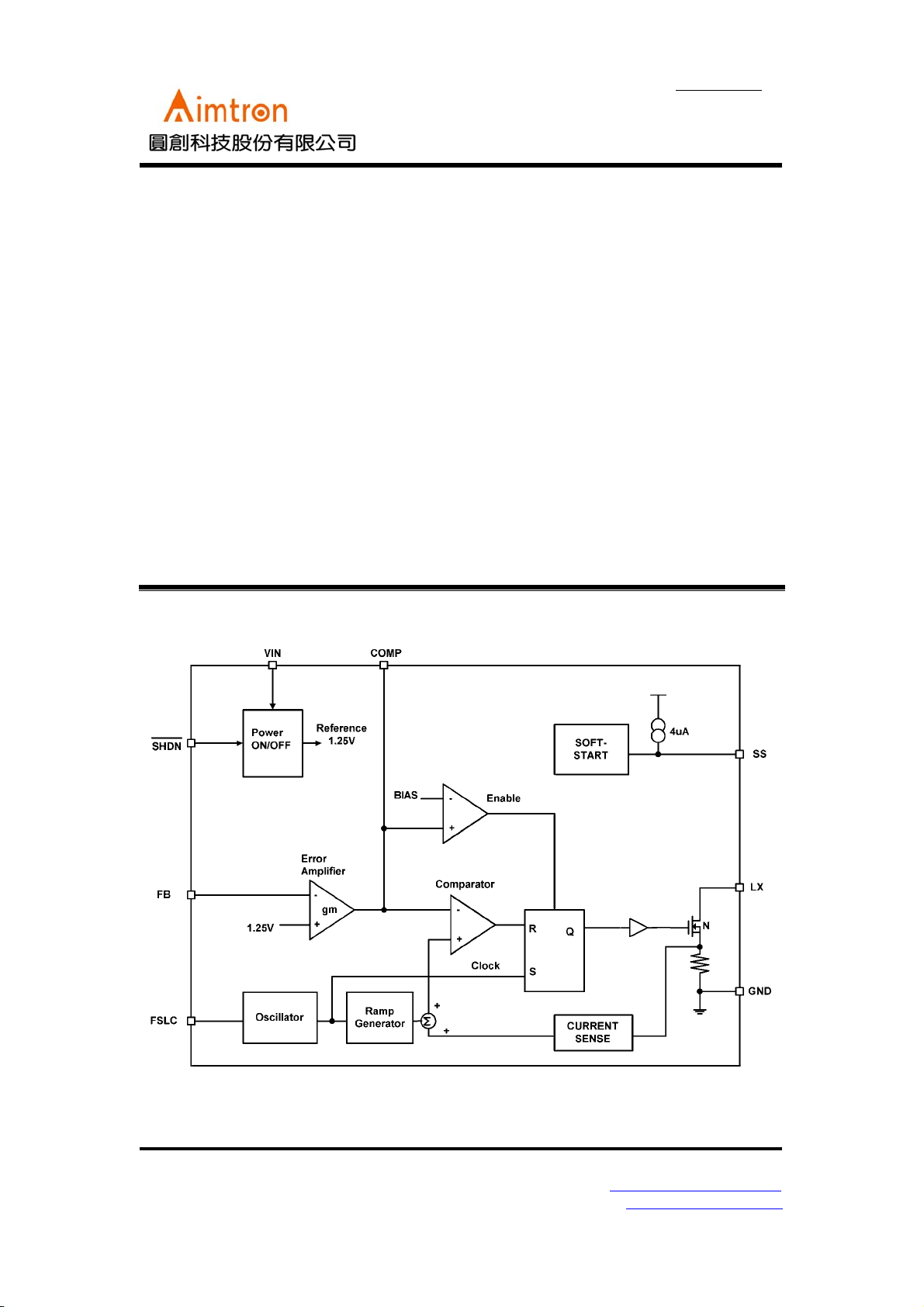
Block Diagram
General Description
The AT1780 is a current-mode step-up DC/DC
converter with a 1.8A, 0.21Ω power MOSFET.
The soft-start function is programmed with an
external capacitor, which sets the input current
ramp rate. It is ideal for generating bias voltages
for LCD panels. Pin selectable frequency 640KHz
or 1.2MHz operation results in a low noise output
that is easy to filter and faster loop performance.
An external compensation pin provides the user
flexibility in determining loop dynamics, allowing
the use of small, low equivalent series resistance
(ESR) ceramic output capacitors.
.
2F, No.10, Prosperity RD. II, Science-Based Industrial Park, Hsinchu 300,Taiwan, R.O.C.
Tel: 886-3-563-0878 WWW: http://www.aimtron.com.tw
Fax: 886-3-563-0879 Email: service@aimtron.com.tw
1
Page 2
AT1780
640kHz/1.2MHz,Low-Noise Step-Up
Current-Mode PWM Controller
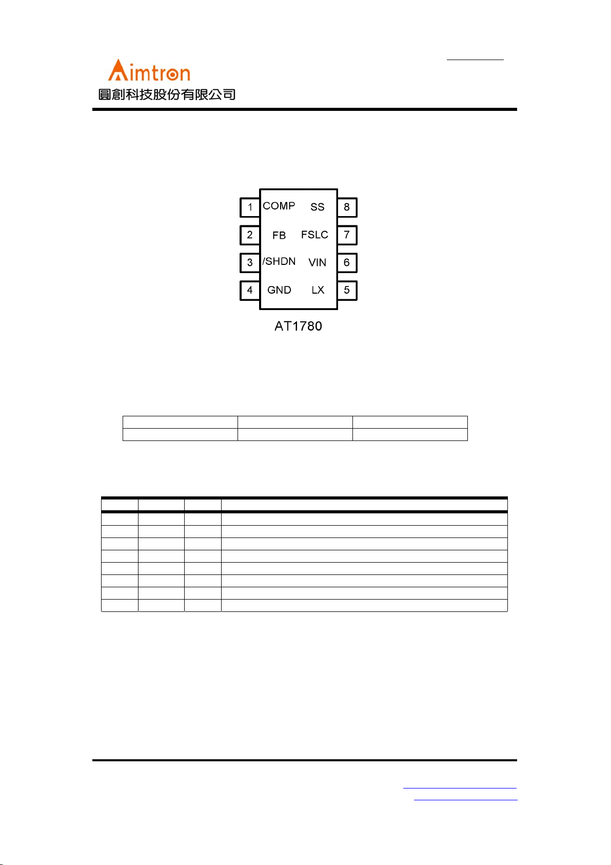
Pin Configuration
Preliminary
Ordering Information
Part number Package Marking
AT1780 8µMAX
Pin Description
Pin No. Symbol I/O Description
1 COMP - Compensation network connection.
2 FB I Output voltage feedback input
3 /SHDN I Shutdown control input, active low
4GND
5 LX O Switch Pin.
6VIN
7 FSLC I Frequency select input. Ground=640KHz, VIN=1.2MHz
8 SS — Soft-Start control pin.
Ground
-
Power supply pin.
-
2F, No.10, Prosperity RD. II, Science-Based Industrial Park, Hsinchu 300,Taiwan, R.O.C.
Tel: 886-3-563-0878 WWW: http://www.aimtron.com.tw
Fax: 886-3-563-0879 Email: service@aimtron.com.tw
2
Page 3
AT1780
640kHz/1.2MHz,Low-Noise Step-Up
Current-Mode PWM Controller
Absolute Maximum Ratings
Preliminary
Rated ValueParameter Condition
Unit
Min. Max.
LX to GND — -0.3 +14 V
IN, /SHDN, FREG, FB to GND — -0.3 +8 V
SS, COMP to GND — -0.3 VIN+0.3 V
RMS LX pin current — — 1.2 A
Continuous power dissipation
8pin μMAX(TA=+70℃)
Operating temperature — -30 +85
Junction temperature — — +150
Storage temperature — -40 +150
Lead temperature — — +300
Stresses beyond those listed under “Absolute Maximum Ratings” may cause permanent damage to the device. These are
stress ratings only, and functional operation of the device at these or any other conditions beyond those indicated in the
operational sections of the specifications is not implied. Exposure to absolute maximum rating conditions for extended
periods may affect device reliability.
—330 mW
0
C
0
C
0
C
0
C
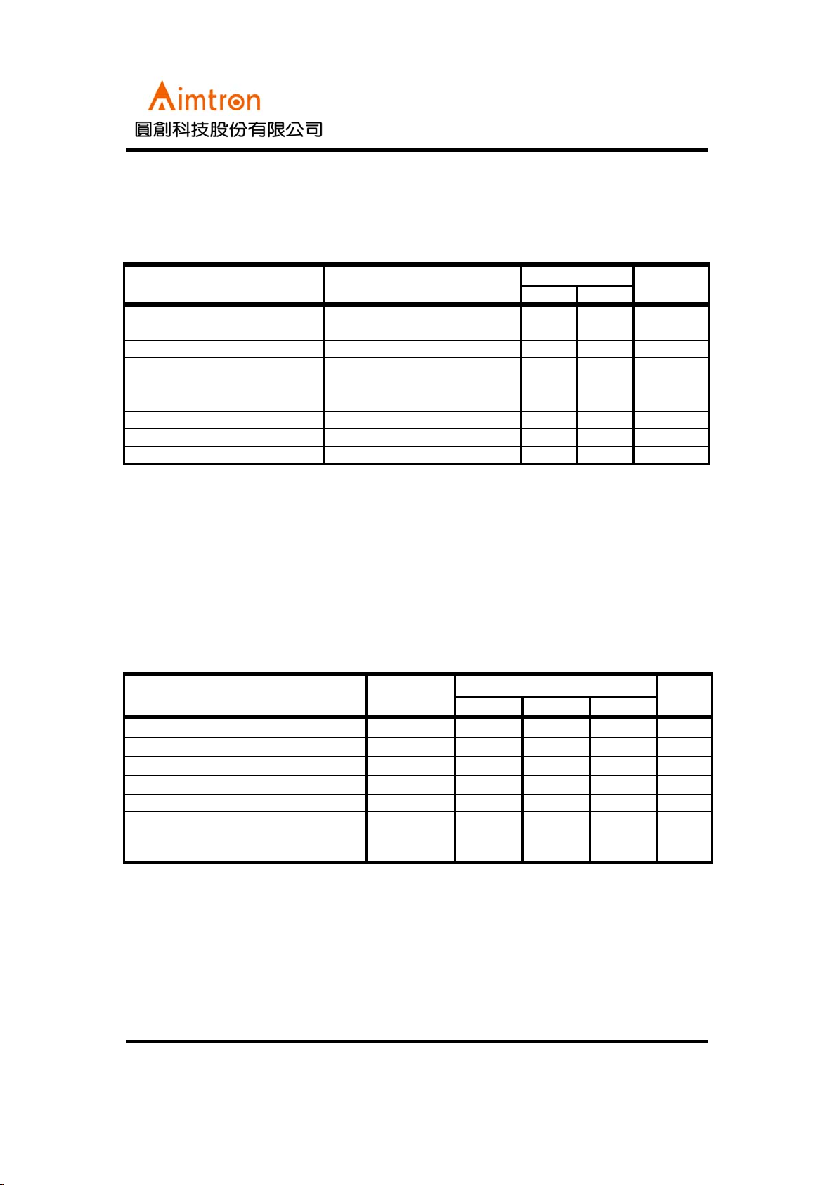
Recommended Operating Conditions
(Ta=+250C)
Power supply voltage V
SS pin capacitance C
Phase compensation capacitance C
Phase compensation capacitance C
Phase compensation resistance R
Oscillation frequency
f
f
Operating temperature T
CC
PE
COMP1
COMP2
COMP
OSC1
OSC2
OP
Va lu esParameter Symbol
Min. Typ. Max.
2.5 -- 7
-- 0.033 --
-- 680 --
-- 20 --
-- 180 -- KΩ
540 708 740 kHz
1000 1220 1500 kHz
-30 +25 +85 °C
Unit
V
μF
pF
pF
2F, No.10, Prosperity RD. II, Science-Based Industrial Park, Hsinchu 300,Taiwan, R.O.C.
Tel: 886-3-563-0878 WWW: http://www.aimtron.com.tw
Fax: 886-3-563-0879 Email: service@aimtron.com.tw
3
Page 4

AT1780
640kHz/1.2MHz,Low-Noise Step-Up
Current-Mode PWM Controller
Electrical Characteristics
(VIN = SHDN = 3V, FREQ = GND, TA =-20℃ to +85℃, unless otherwise noted. Typical values are at TA = +25℃.)
Preliminary
Entire device
Error amplifier
Sawtooth wave
oscillator (OSC)
N-CHANNEL
SWITCH
SOFT-START
CONTROL INPUTS
Va lu esParameter Symbol Condition
Unit
Min. Typ. Max.
Input Supply Range V
VIN Undervoltage
Lockout
IN
UVLO
V
rising, typical
IN
hysteresis is 40mV,LX
remains off below this
2.5 -- 7 V
2.25 2.46 2.52 V
level
Quiescent Current I
VFB = 1.3V, not
switching
IN
0.218 0.35
mA
VFB = 1.0V, switching 2.045 5
Shutdown Supply
Current
I
Feedback Voltage V
FB Input Bias Current I
Feedback-Voltage Line
Regulation
Transconductance gm
/SHDN = GND 16
IN
Level to produce
FB
V
= 1.24V
COMP
VFB = 1.25V 0 40 nA
FB
1.245 1.25 1.255 V
Level to produce
V
= 1.24V,
COMP
2.6V < V
ΔI = 5µA
< 5.5V
IN
0.05 0.15 %/V
-280-
μA
μmhos
Voltage Gain Av -- 500 V/V
Frequency fosc
Maximum Duty Cycle DC
Current Limit I
On-Resistance R
Leakage Current I
Current-Sense
Transresistance
LXOFF
R
Reset Switch
Resistance
Charge Current
Input Low Voltage V
Input High Voltage V
Hysteresis
FREQ Pull-Down
Current
/SHDN Input Current I
I
SHDN
FREQ = GND 540 650 740
FREQ = IN 1050 1200 1350
FREQ = GND 79 91.3 92
FREQ = IN 82.1
VFB = 1V, duty cycle =
LIM
65%
ILX = 1.2A
ON
1.7 - 2.5 A
VLX = 12V 0.01 20
CS
V
/SHDN, FREQ;
IL
V
/SHDN, FREQ;
IH
V
= 1.2V
SS
= 2.6V to 5.5V
IN
= 2.6V to 5.5V
IN
0.3 0.45 0.65 V/A
1.5 2.55 7
SHDN, FREQ 0.07×
FREQ
1.5 5 9
0.21 0.3
100
0.51×
V
IN
0.57×
V
IN
V
IN
0.001 1
kHz
%
Ω
μA
Ω
μA
V
V
V
μA
μA
2F, No.10, Prosperity RD. II, Science-Based Industrial Park, Hsinchu 300,Taiwan, R.O.C.
Tel: 886-3-563-0878 WWW: http://www.aimtron.com.tw
Fax: 886-3-563-0879 Email: service@aimtron.com.tw
4
Page 5

AT1780
640kHz/1.2MHz,Low-Noise Step-Up
Current-Mode PWM Controller
Typical Application Circuit
Preliminary
2F, No.10, Prosperity RD. II, Science-Based Industrial Park, Hsinchu 300,Taiwan, R.O.C.
Tel: 886-3-563-0878 WWW: http://www.aimtron.com.tw
Fax: 886-3-563-0879 Email: service@aimtron.com.tw
5
Page 6

AT1780
640kHz/1.2MHz,Low-Noise Step-Up
Current-Mode PWM Controller
Small Outline 8-pin Plastic µMAX
Preliminary
SYMBOL
A 0.037 0.043 0.94 1.10 -
A1 0.002 0.006 0.05 0.15 -
B 0.010 0.014 0.25 0.36 C 0.005 0.007 0.13 0.18 D 0.116 0.120 2.95 3.05 -
e 0.0256 BSC 0.65 BSC E 0.116 0.120 2.95 3.05 H 0.188 0.198 4.78 5.03
L 0.016 0.026 0.41 0.66 -
α
S 0.207 BSC 0.525 BSC -
2F, No.10, Prosperity RD. II, Science-Based Industrial Park, Hsinchu 300,Taiwan, R.O.C.
Tel: 886-3-563-0878 WWW: http://www.aimtron.com.tw
Fax: 886-3-563-0879 Email: service@aimtron.com.tw
INCHES MILLIMETERS
MIN MAX MIN MAX
0° 6° 0° 6°
6
NOTES
Page 7

AT1780
C
640kHz/1.2MHz,Low-Noise Step-Up
Current-Mode PWM Controller
Reflow Condition (IR/Convection or VPR Reflow)
Reference JEDEC Standard J-STD-020A
Preliminary
Classification Reflow Profiles
Convection or
IR/Convction
Average Heating Rate(180°C to peak) 5°C/second max. 10°C/second max.
Preheat Temperature(125±20°C)
Temperature maintained above 180°C
Time within 5°C of actual Peak
Temperature
Peak Temperature Range(Note 1)
Cooling Rate
Time 25°C to Peak Temperature
*1 The maximum peak temperatures for IR and VP reflow are depending on package dimensions.
120 seconds max.
10~150 seconds
10~20 seconds 60 seconds
219~225°C or
235~240°C
6°C /second max. 10°C/second max.
6 minutes max.
219~225°C or
235~240°C
Package Reflow Conditions
Pkg. Thickness ≥2.5mm
and all bags
Convection 219~225
VPR 219~225
°C
IR/Convection 219~225
°C
°C
Pkg. Thickness <2.5mm
and
Pkg. Volume ≥350 mm
Pkg. Thickness <2.5mm
and
3
Pkg. Volume <350 mm
Convection 235~240
VPR 235~240
IR/Convection 235~240
VPR
3
°C
°C
°
2F, No.10, Prosperity RD. II, Science-Based Industrial Park, Hsinchu 300,Taiwan, R.O.C.
Tel: 886-3-563-0878 WWW: http://www.aimtron.com.tw
Fax: 886-3-563-0879 Email: service@aimtron.com.tw
7
Page 8

AT1780
640kHz/1.2MHz,Low-Noise Step-Up
Current-Mode PWM Controller
Preliminary
2F, No.10, Prosperity RD. II, Science-Based Industrial Park, Hsinchu 300,Taiwan, R.O.C.
Tel: 886-3-563-0878 WWW: http://www.aimtron.com.tw
Fax: 886-3-563-0879 Email: service@aimtron.com.tw
8
 Loading...