

Page 1
AT1743
2-Channel PWM Controller for LCD Display
Features
• High-accuracy reference voltage circuit (±1%).
• Built-in short-circuit protection circuit.
• Built-in Undervoltage Lockout protection.
• Internal 2.5V Reference supply.
• Variable Dead time provides control over total
Range.
Applications
• LCD Display
• Portable equipment
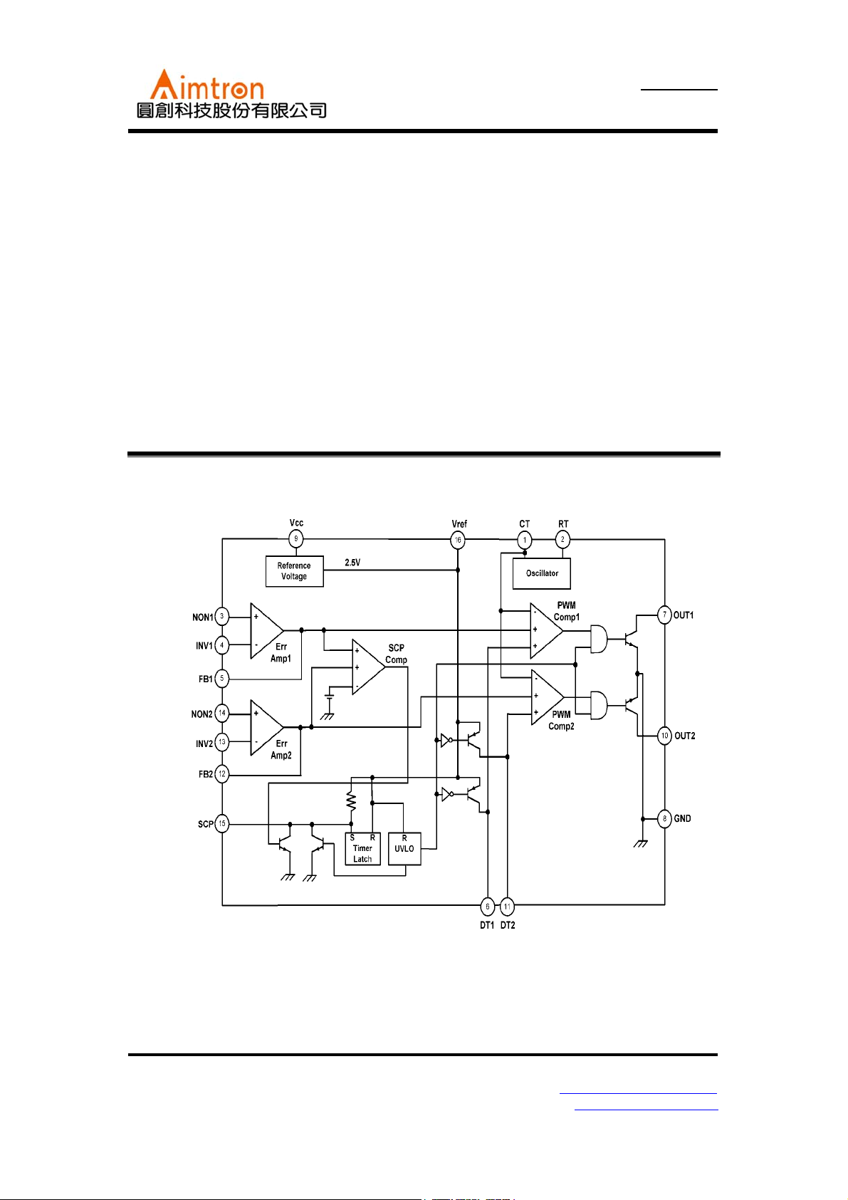
Block Diagram
General Description
The AT1743 is 2-channel PWM switching
regulator controllers that contains an on-chip 2.5V
reference, two error amplifier, an adjustable
oscillator, two dead-time comparators, undervoltage lockout circuitry and 2 common-emitter
output. It is idea for step-up, step-down, and
inverting converter.
2F, No.10, Prosperity RD. II, Science-Based Industrial Park, Hsinchu 300,Taiwan, R.O.C.
Tel: 886-3-563-0878 WWW: http://www.aimtron.com.tw
Fax: 886-3-563-0879 Email: service@aimtron.com.tw
1
Page 2
AT1743
2-Channel PWM Controller for LCD Display
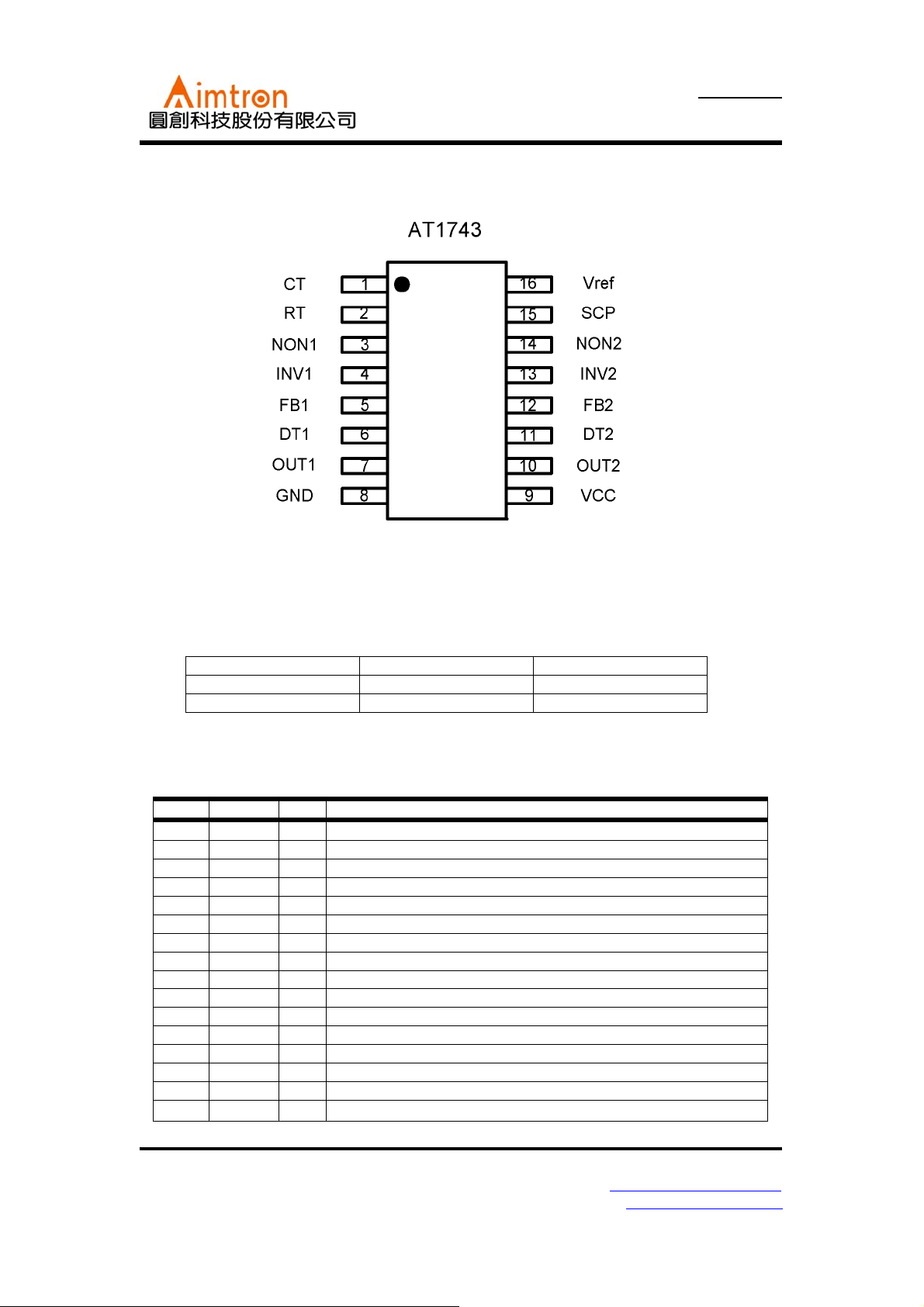
Pin Configuration
Ordering Information
Part number Package Marking
AT1743 TSSOP16 AT1743P
---
Pin Description
Pin No. Symbol I/O Description
1 CT -- External timing capacitor
2 RT -- External timing resistor
3 NON1 I Positive input for error amplifier 1
4 INV1 I Negative input for error amplifier 1
5 FB1 O Error amplifier 1 output
6 DT1 I Output 1 dead time / soft start setting
7 OUT1 O Output 1
8 GND -- Ground
9 Vcc -- Power supply
10 OUT2 O Output 2
11 DT2 I Output 2 dead time / soft start setting
12 FB2 O Error amplifier 2 output
13 INV2 I Negative input for error amplifier 2
14 NON2 I Positive input for error amplifier 2
15 SCP -- Time latch setting
16 Vref O
Reference voltage output(2.5V)
2F, No.10, Prosperity RD. II, Science-Based Industrial Park, Hsinchu 300,Taiwan, R.O.C.
Tel: 886-3-563-0878 WWW: http://www.aimtron.com.tw
Fax: 886-3-563-0879 Email: service@aimtron.com.tw
2
Page 3
AT1743
2-Channel PWM Controller for LCD Display
Absolute Maximum Ratings
(Ta=+250C)
Parameter Symbol
Power supply voltage Vcc 30 V
Power dissipation Pd 450*
Operating temperture Topr -30~+85
Storage temperture Tstg -55~+125
Output current Io 120*
Output voltage Vo 30
*1 When mounted on 70mm×70mm×1.6mm glass epoxy board. Reduced by 6.5mw for each increase in Ta of 1℃ over 25℃.
*2 Should not exceed Pd and values.
Limits
Unit
1
mW
℃
℃
2
mA
V
Recommended Operating Conditions
(Ta=+250C)
Va lu esParameter Symbol
Min. Typ. Max.
Power supply voltage V
CC
3.6 6.0 25
Output current Io -- -- 100 mA
Output voltage Vo -- -- 25 V
Error amplifier input voltage V
Timing capacitor C
Timing resistor
Oscillator frequency F
OM
CT
R
RT
OSC
0.3 -- 1.6 V
100 -- 15000 pF
5.1 -- 50
10 -- 800 kHz
Unit
V
kΩ
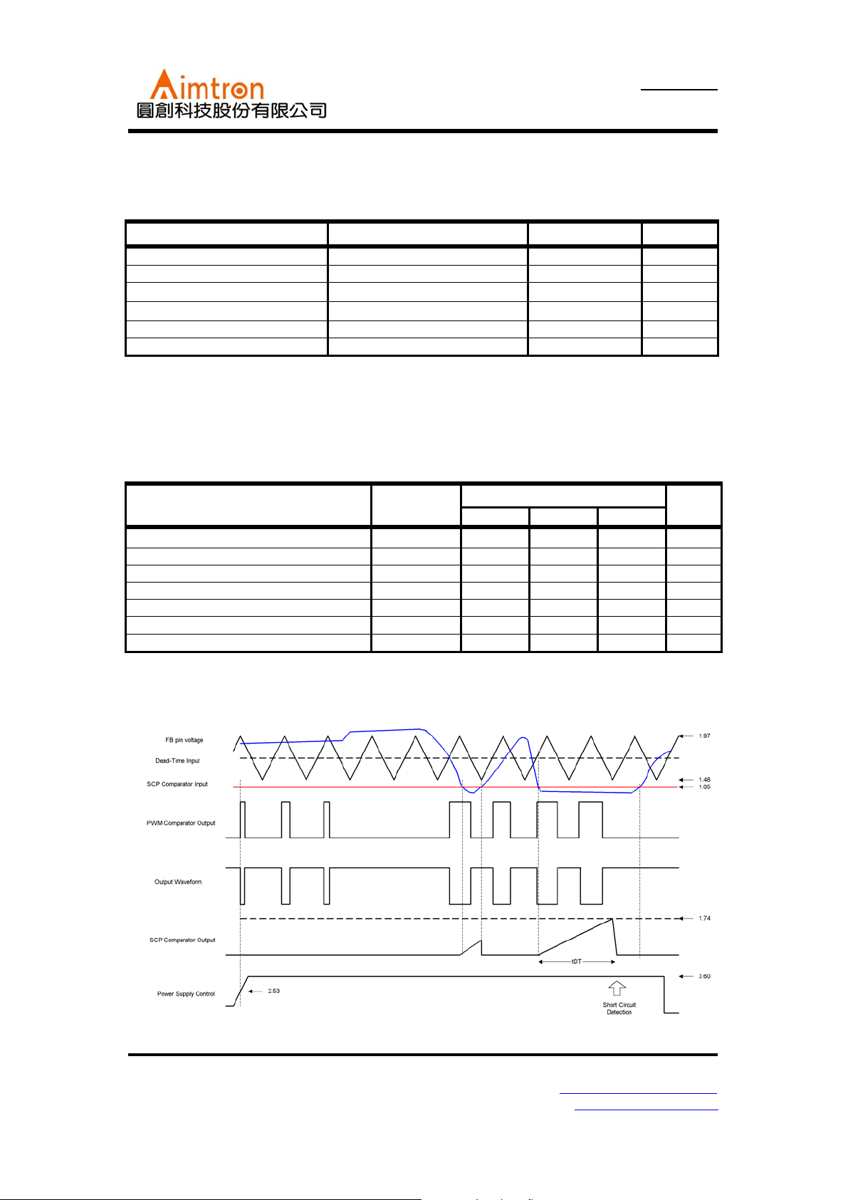
Timing chart
2F, No.10, Prosperity RD. II, Science-Based Industrial Park, Hsinchu 300,Taiwan, R.O.C.
Tel: 886-3-563-0878 WWW: http://www.aimtron.com.tw
Fax: 886-3-563-0879 Email: service@aimtron.com.tw
3
Page 4

AT1743
2-Channel PWM Controller for LCD Display
Electrical Characteristics (unless otherwise noted, Ta=25℃, and Vcc=6V )
Va lu esParameter Symbol Condition
Min. Typ. Max.
Reference voltage
block
Triangular wave
oscillator
Protection circuit
Rest period
adjustment circuit
Low-voltage input
miss-operation
prevention circuit
Error amplifier
PWM comparator
Output block
Total device
Output voltage Vref
Input stability V
Load stability V
Oscillation frequency Fosc
Frequency deviation F
Threshold voltage V
Standby voltage V
Latch voltage V
Source current I
Comparator threshold
voltage
V
Input threshold voltage
(fosc=10kHz)
V
On duty cycle D
Input bias current I
Latch mode source
current
Latch input voltage V
Threshold voltage V
Input offset voltage V
Input offset current I
Input bias current I
Open circuit gain AV -- 70 85 -- dB
Common-mode input
voltage range
Common-mode
rejection ratio
Maximum output
voltage
V
CMRR -- 60 80 -- dB
V
Minimum input voltage V
Output sink current I
Output source current I
Input threshold voltage
(fosc=10kHz)
V
Saturation voltage V
Leak current I
REAK
Standby current I
Average current
consumption
I
Iref=1mA
Vcc=3.6~25V -- 1 10 mV
DL1
Iref=0~5mA
DLO
R
=10kΩ, CCT=220pF
RT
Vcc=3.6~25V -- 1 -- %
DV
IT
No pull up -- 50 100 mV
STB
No pull up -- 30 100 mV
LT
SCP
Pin 5, Pin 12 0.9 1.05 1.2 V
CT
Duty cycle=0%
V
t0
Duty cycle=100% 1.32 1.48 1.64 V
t100
-- 1.48 1.64 1.80 V
--
Divide Vref using 13
ON
kΩ and 27 kΩ
DT1, DT2=2.0V
BDT
DT1, DT2=0V 200 560 --
I
DT
IDT=40μA
DT
UT
IO
IO
IB
Vcc=3.6~25V 0.3 -- 1.6 V
OM
OH
OL
FB=1.25V 3 20 -- mA
OI
FB=1.25V
OO
V
Duty cycle=0% 1.79 1.97 2.15 V
t0
Duty cycle=100%
t100
Io=75mA -- 0.8 1.2 V
SAT
-- -- 2.53 -- V
-- -- -- 6 mV
-- -- -- 30 nA
-- -- 15 100 nA
-- 2.3 2.5 -- V
-- -- 0.7 0.9 V
Vo=25V
When output is off -- 1.3 1.8 mA
CCS
RRT=10 kΩ
CCA
2.48 2.5 2.53 V
-- 1 10 mV
320 400 480 kHz
1.5 2.5 3.5
1.79 1.97 2.15 V
45 55 65 %
-- 0.1 1
2.28 2.48 -- V
45 75 --
1.32 1.48 1.64 V
-- 0 5
-- 1.6 2.3 mA
Unit
μA
μA
μA
μA
μA
2F, No.10, Prosperity RD. II, Science-Based Industrial Park, Hsinchu 300,Taiwan, R.O.C.
Tel: 886-3-563-0878 WWW: http://www.aimtron.com.tw
Fax: 886-3-563-0879 Email: service@aimtron.com.tw
4
Page 5

2-Channel PWM Controller for LCD Display
Timing Curve
AT1743
2F, No.10, Prosperity RD. II, Science-Based Industrial Park, Hsinchu 300,Taiwan, R.O.C.
Tel: 886-3-563-0878 WWW: http://www.aimtron.com.tw
Fax: 886-3-563-0879 Email: service@aimtron.com.tw
5
Page 6

2-Channel PWM Controller for LCD Display
AT1743
2F, No.10, Prosperity RD. II, Science-Based Industrial Park, Hsinchu 300,Taiwan, R.O.C.
Tel: 886-3-563-0878 WWW: http://www.aimtron.com.tw
Fax: 886-3-563-0879 Email: service@aimtron.com.tw
6
Page 7

2-Channel PWM Controller for LCD Display
Application Circuit: Step-Down converter
AT1743
2F, No.10, Prosperity RD. II, Science-Based Industrial Park, Hsinchu 300,Taiwan, R.O.C.
Tel: 886-3-563-0878 WWW: http://www.aimtron.com.tw
Fax: 886-3-563-0879 Email: service@aimtron.com.tw
7
Page 8

AT1743
2-Channel PWM Controller for LCD Display
Package Outline 16-pin TSSOP
SYMBOL
MILLIMETERS INCHES
MIN TYP MAX MIN TYP MAX
A 1.05 1.10 1.20 0.041 0.043 0.047
A1 0.05 0.10 0.15 0.002 0.004 0.006
A2 - 1.00 1.05 - 0.039 0.041
b 0.20 0.25 0.28 0.008 0.010 0.011
C - 0.127 - - 0.005 D 4.90 5.075 5.10 0.193 0.1998 0.200
E 6.20 6.40 6.60 0.244 0.252 0.260
E1 4.30 4.40 4.50 0.170 0.173 0.177
L 0.50 0.60 0.70 0.020 0.024 0.028
e - 0.65 - - 0.026 -
y - - 0.076 - - 0.003
θ 0° 8° 0° 8°
2F, No.10, Prosperity RD. II, Science-Based Industrial Park, Hsinchu 300,Taiwan, R.O.C.
Tel: 886-3-563-0878 WWW: http://www.aimtron.com.tw
Fax: 886-3-563-0879 Email: service@aimtron.com.tw
8
Page 9

C
AT1743
2-Channel PWM Controller for LCD Display
Reflow Condition (IR/Convection or VPR Reflow)
Reference JEDEC Standard J-STD-020A
Classification Reflow Profiles
Convection or
IR/Convction
Average Heating Rate(180°C to peak) 5°C/second max. 10°C/second max.
Preheat Temperature(125±20°C)
Temperature maintained above 180°C
Time within 5°C of actual Peak
Temperature
Peak Temperature Range(Note 1)
Cooling Rate
Time 25°C to Peak Temperature
*1 The maximum peak temperatures for IR and VP reflow are depending on package dimensions.
120 seconds max.
10~150 seconds
10~20 seconds 60 seconds
219~225°C or
235~240°C
6°C /second max. 10°C/second max.
6 minutes max.
219~225°C or
235~240°C
Package Reflow Conditions
Pkg. Thickness ≥2.5mm
and all bags
Convection 219~225
VPR 219~225
°C
IR/Convection 219~225
°C
°C
Pkg. Thickness <2.5mm
and
Pkg. Volume ≥350 mm
Pkg. Thickness <2.5mm
and
3
Pkg. Volume <350 mm
Convection 235~240
VPR 235~240
IR/Convection 235~240
VPR
3
°C
°C
°
2F, No.10, Prosperity RD. II, Science-Based Industrial Park, Hsinchu 300,Taiwan, R.O.C.
Tel: 886-3-563-0878 WWW: http://www.aimtron.com.tw
Fax: 886-3-563-0879 Email: service@aimtron.com.tw
9
 Loading...