

Page 1
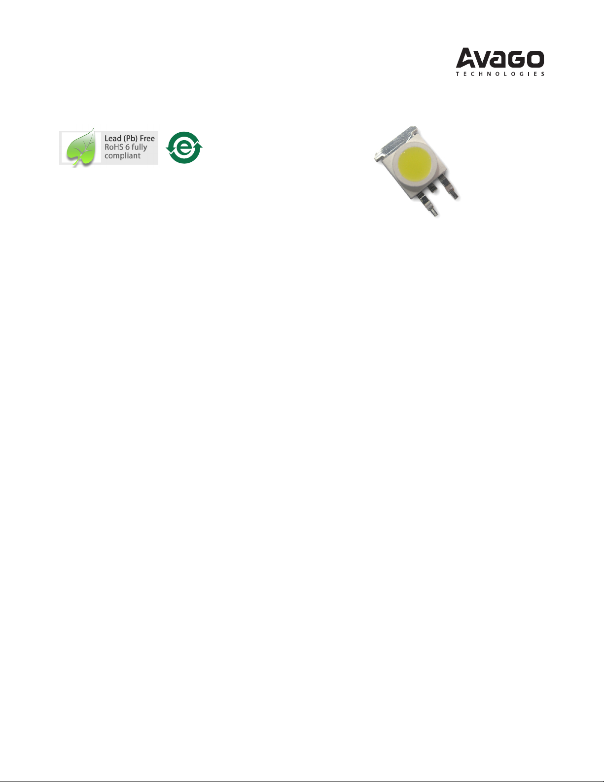
ASMT- Mx2x / ASMT- MxEx
MoonstoneTM 3W Power LED Light Source
Data Sheet
Description
The Moonstone™ 3W Power LED Light Source is a high
performance energy ecient device which can handle
high thermal and high driving current. The exposed pad
design has excellent heat transfer from the package to the
motherboard.
The Cool White Power LED is available in various color
temperature ranging from 4000K to 10000K and Warm
White Power LED ranging from 2600K to 4000K.
The low prole package design is suitable for a wide variety
of applications especially where height is a constraint.
The package is compatible with reow soldering. This
will give more freedom and exibility to the light source
designer.
Applications
• Sign backlight
• Safety, exit and emergency sign lightings
• Specialty lighting such as task lighting and reading
lights
• Retail display
• Commercial lighting
• Accent or marker lightings, strip or step lightings
• Portable lightings, bicycle head lamp, torch lights.
• Decorative lighting
• Architectural lighting
• Pathway lighting
• Street lighting
• Pedestrian street lighting
• Tunnel lighting
Features
• Available in Cool White & Warm White color
• Energy ecient
• Exposed pad for excellent heat transfer
• Suitable for reow soldering process
• High current operation
• Long operation life
• Wide viewing angle
• Silicone encapsulation
• Non-ESD sensitive (threshold > 16KV)
• MSL 4 products
• Available in both electrically isolated and non-isolated
metal heat slug
Specications
• InGaN Technology
• 4.3 V (max) at 700 mA
• 120° viewing angle
Page 2

Package Dimensions
Metal Slug
Cathode
Anode1
2
3
10.00
8.50
3
1
2
8.50
Ø 5.26
Ø 8.00
5.08
0.81
2.00
5.25
1.30
10.60
1.27
3.30
Heat Sink
LED
ZENER
+
−
Notes:
1. All dimensions are in millimeters.
2. Unless otherwise stated, the tolerance for dimension is ±0.1mm.
3. Metal slug is connected to anode for electrically non-isolated option.
Device Selection Guide (TJ = 25°C)
Color
Cool White ASMT-MW20 124 145 161 700 InGaN No
Warm White ASMT-MY20 95 125 161 700 InGaN No
Cool White
Diused
Warm White
Diused
Notes:
1. ΦV is the total luminous ux output as measured with an integrating sphere at 25ms mono pulse condition.
2. Flux tolerance is ±10%.
Part Number
ASMT-MW22 Yes
ASMT-MY22 Yes
ASMT-MWE0 95 125 161 700 InGaN No
ASMT-MWE2 Yes
ASMT-MYE0 95 110 161 700 InGaN No
ASMT-MYE2 Yes
Luminous Flux, Φ
v
[1,2]
(lm)
Test Current
(mA)
Die
Technology
Electrically
Isolated Metal SlugMin. Typ. Max.
2
Page 3
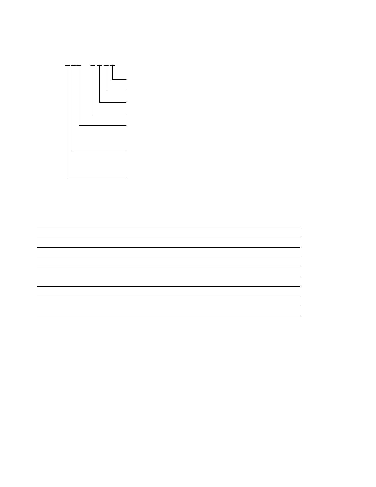
Part Numbering System
ASMT-M x x x – N x1x2x3x
4
Packaging Option
Color Bin Selection
Max Flux Bin Selection
Min Flux Bin Selection
Color
W – Cool White
Y – Warm White
Silicone Type
2 – Non-diffused
E – Diffused
Heat Sink
0 – Electrically Non-isolated
2 – Electrically Isolated
Please refer to Page 6 for selection details.
Absolute Maximum Ratings
Parameter ASMT-Mx2x / ASMT-MxEx Units
DC Forward Current
Peak Pulsing Current
Power Dissipation 3010 mW
Reverse Voltage 5 V
LED Junction Temperature 125 °C
Operating Metal Slug Temperature Range at 700mA -40 to +95 °C
Storage Temperature Range -40 to +120 °C
Soldering Temperature Refer to Figure 8
Note:
1. Derate linearly based on Figure 6.
2. Pulse condition: duty factor = 10%, Frequency = 1 kHz.
[1]
[2]
700 mA
1000 mA
3
Page 4

Optical Characteristics at 700 mA (TJ = 25°C)
Correlated Color Temperature,
CCT (Kelvin)
Part Number Color
ASMT-MW20
ASMT-MW22
ASMT-MY20
ASMT-MY22
ASMT-MWE0
ASMT-MWE2
ASMT-MYE0
ASMT-MYE2
Notes:
1. θ½ is the o-axis angle where the luminous intensity is ½ the peak intensity.
Cool White 4000 10000 120 52
Warm White 2600 4000 120 45
Cool White Diused 4000 10000 120 45
Warm White Diused 2600 4000 120 41
Min. Max. Typ. Typ.
Viewing Angle
[1]
2θ½
(°)
Electrical Characteristic at 700 mA (TJ = 25°C)
Temperature Coecient
Forward Voltage,
VF (Volts) at IF = 700 mA
Dice Type
InGaN 3.6 4.0 4.3 10 -1.5 to -3.5
Note:
1. Rθ
is the Thermal Resistance from LED junction to metal slug.
j-ms
Min. Typ. Max. Typ. Typ.
Thermal Resistance,
(°C/W)
[1]
Rθ
j-ms
of Forward Voltage (mV/°C),
∆VF/∆T
Luminous Eciency
(lm/W)
J
Typical Characteristic at 350 mA (TJ = 25°C)
Part Number Color
ASMT-MW20
ASMT-MW22
ASMT-MY20
ASMT-MY22
ASMT-MWE0
ASMT-MWE2
ASMT-MYE0
ASMT-MYE2
Cool White 80 3.6
Warm White 70 3.6
Cool White Diused 70 3.6
Warm White Diused 65 3.6
Luminous Flux,
ΦV (lm)
Forward Voltage,
VF (Volts)
Typ. Typ.
4
Page 5

0.0
0.1
0.2
0.3
0.4
0.5
0.6
0.7
0.8
0.9
1.0
380 430 480 530 580 630 680 730 780
WAVELENGTH - nm
RELATIVE INTENSITY
WARM WHITE
COOL WHITE
0
0.1
0.2
0.3
0.4
0.5
0.6
0.7
0.8
0.9
1
0 100 200 300 400 500 600 700
DC FORWARD CURRENT - mA
RELATIVELUMINOUS FLUX
(NORMALIZED AT700 mA)
0
100
200
300
400
500
600
700
0 1 2 3 4 5
FORWARD VOLTAGE - V
FORWARD CURRENT - mA
0
0.1
0.2
0.3
0.4
0.5
0.6
0.7
0.8
0.9
1
-90 -60 -30 0 30 60 90
ANGULAR DISPLACEMENT - DEGREES
NORMALIZED INTENSITY
0.0
0.1
0.2
0.3
0.4
0.5
0.6
0.7
0.8
0.9
1.0
1.1
1.2
-50 -25 0 25 50 75 100 125
JUNCTION TEMPERATURE, T
J
- °C
RELATIVE LIGHT OUTPUT
(NORMALIZED AT 25°C)
WARM WHITE
COOL WHITE
Figure 1. Relative Intensity vs. Wavelength. Figure 2. Relative Luminous Flux vs. Forward Current.
Figure 3. Forward Current vs. Forward Voltage. Figure 4. Radiation Pattern.
Figure 5. Relative Light Output vs. Junction Temperature.
5
Page 6

Figure 6. Maximum Forward Current vs. Ambient Temperature.
(Acc. to J-STD-020C)
217°C
200°C
60 - 120 SEC.
6°C/SEC. MAX.
3°C/SEC. MAX.
3°C/SEC. MAX.
150°C
255 - 260°C
100 SEC. MAX.
10 - 30 SEC.
TIME
TEMPERATURE
10.70±0.10
8.40±0.10
3.1±0.10
5.08±0.10
1.00±0.10
17.00±0.20
0
100
200
300
400
500
600
700
800
0 20 40 60 80 100 120 140
TA- AMBIENT TEMPERATURE - °C
MAX ALLOWABLE DC CURRENT - mA
0
100
200
300
400
500
600
700
800
0 20 40 60 80 100 120 140
TMS- METAL SLUG TEMPERATURE - °C
MAX ALLOWABLE DC CURRENT - mA
Rθ
J-MS
= 10°C/W
Rθ
J-A
= 30°C/W
Rθ
J-A
= 20°C/W
Rθ
J-A
= 25°C/W
Derated based on TJMAX = 125°C, Rθ
= 20°C/W, 25°C/W and 30°C/W.
J-A
Figure 7. Maximum Forward Current vs. Metal Slug Temperature.
Derated based on TJMAX = 125°C, Rθ
= 10°C/W.
J-MS
Figure 8. Recommended Reow Soldering. Figure 9. Recommended soldering land pattern.
6
Page 7

Option Selection Details
Flux Bin Limit [x1 x2]
ASMT-Mxxx – N x1 x2 x3 x4
x1 – Minimum Flux Bin
x2 – Maximum Flux Bin
x3 – Color Bin Selection
x4 – Packaging Option
Color Bin Selections [x3]
Individual reel will contain parts from one full bin only.
Cool White
O Full Distribution
A A only
B B only
C C only
D D only
E E only
F F only
G G only
H H only
L A and G only
M B and H only
N A and C only
P B and D only
Q E and C only
R F and D only
S G and H only
U E and F only
W C and D only
Z A and B only
1 A, B, C and D only
2 G, H, A and B only
4 C, D, E and F only
Luminous Flux (lm) at IF = 700mA
Bin
L 73.0 95.0
M 95.0 124.0
N 124.0 161.0
Tolerance for each bin limits is ±10%.
Min. Max.
Warm White
O Full Distribution
A A only
B B only
C C only
D D only
E E only
F F only
N A and C only
P B and D only
Q E and C only
R F and D only
U E and F only
W C and D only
Z A and B only
V D and E only
1 A, B, C and D only
4 C, D, E and F only
7
Page 8

Color Bin Limit
0.24
0.26
0.28
0.30
0.32
0.34
0.36
0.38
0.40
0.42
0.44
0.24 0.26 0.28 0 .30 0.32 0.34 0.36 0.38 0 .40 0.42 0.44
X - COORDINATE
Y - COORDINATE
Y - COORDINATE
B
C
E
D
A
F
7k
10k
4.0k
G
H
0.32
0.34
0.36
0.38
0.40
0.42
0.44
0.46
0.48
0.34 0.36 0.38 0.40 0.42 0.44 0.46 0.48 0.50 0.52
X - COORDINATE
B
C
E
D
A
F
3.0k
3.5k
4.0k
2.6k
5.6k
4.5k
Black Body Curve
Black Body Curve
Cool Color Limits
White (Chromaticity Coordinates)
Bin A X 0.367 0.362 0.329 0.329
Y 0.400 0.372 0.345 0.369
Bin B X 0.362 0.356 0.329 0.329
Y 0.372 0.330 0.302 0.345
Bin C X 0.329 0.329 0.305 0.301
Y 0.369 0.345 0.322 0.342
Bin D X 0.329 0.329 0.311 0.305
Y 0.345 0.302 0.285 0.322
Bin E X 0.303 0.307 0.283 0.274
Y 0.333 0.311 0.284 0.301
Bin F X 0.307 0.311 0.290 0.283
Y 0.311 0.285 0.265 0.284
Bin G X 0.388 0.379 0.362 0.367
Y 0.417 0.383 0.372 0.400
Bin H X 0.379 0.369 0.356 0.362
Y 0.383 0.343 0.330 0.372
Tolerance: ± 0.01
Warm Color Limits
White (Chromaticity Coordinates)
Bin A X 0.452 0.488 0.470 0.438
Y 0.434 0.447 0.414 0.403
Bin B X 0.438 0.470 0.452 0.424
Y 0.403 0.414 0.384 0.376
Bin C X 0.407 0.418 0.452 0.438
Y 0.393 0.422 0.434 0.403
Bin D X 0.395 0.407 0.438 0.424
Y 0.362 0.393 0.403 0.376
Bin E X 0.381 0.387 0.418 0.407
Y 0.377 0.404 0.422 0.393
Bin F X 0.373 0.381 0.407 0.395
Y 0.349 0.377 0.393 0.362
Tolerance: ± 0.01
Packaging Option [x4]
Selection Option
0 Tube
1 Tape and Reel
8
Figure 10b. Color bins (Warm White).Figure 10a. Color bins (Cool White).
Example
ASMT-MW20-NLNZ0
ASMT-MW20-Nxxxx – Cool White, Electrically
Non-isolated Heat Sink,
Non-diused
X1 = L – Minimum Flux Bin L
X2 = N – Maximum Flux Bin N
X3 = Z – Color Bin A and B only
X4 = 0 – Tube Option
Page 9

Packing Tube – Option 0
535.00
1.00
5.45
5.80
4.65
5.50
10.10
37.00
8.30
TOP VIEW
SIDE VIEW
Figure 11. Tube dimensions.
Tape & Reel – Option 1
Figure 12. Carrier tape dimensions.
Dim Value
A
O
B
O
K
O
E 1.75±0.10
F 11.50±0.10
W 24.0±0.10
P 16.0±0.10
Q'ty/Reel 250 units
All dimensions in millimeters.
8.80±0.10
16.45±0.10
3.60±0.1
9
Page 10

R10.00
60.0º
∅268.00
∅330.00 ± 1.00
∅99.50 ± 1.00
2.30 2.30
24.0
+1.00
−0.00
∅
13.50 ± 0.50
2.50 ± 0.50
R10.50 ± 0.50
120.0º
END
MINIMUM OF 160 mm
OF EMPTY COMPONENT
POCKETS SEALED WITH
COVER TAPE.
MOUNTED WITH
COMPONENTS
MINIMUM OF 390 mm OF EMPTY COMPONENT
POCKETS SEALED WITH COVER TAPE.
START
Figure 13. Carrier tape leader and trailer dimensions.
Reel Dimension
Figure 14. Reel dimensions. Reel dimensions.
10
Page 11

Handling Precaution
The encapsulation material of the product is made of
silicone for better reliability of the product. As silicone is
a soft material, please do not press on the silicone or poke
a sharp object onto the silicone. These might damage the
product and cause premature failure. During assembly or
handling, the unit should be held on the body only. Please
refer to Avago Application Note AN 5288 for detail information.
Moisture Sensitivity
This product is qualied as Moisture Sensitive Level 4 per
Jedec J-STD-020. Precautions when handling this moisture
sensitive product is important to ensure the reliability of
the product. Do refer to Avago Application Note AN5305
Handling of Moisture Sensitive Surface Mount Devices for
details.
A. Storage before use
– Unopen moisture barrier bag (MBB) can be stored at
<40°C/90%RH for 12 months. If the actual shelf life
has exceeded 12 months and the humidity indicator
card (HIC) indicates that baking is not required, then
it is safe to reow the LEDs per the original MSL
rating.
– It is not recommended to open the MBB prior to
assembly (e.g. for IQC).
B. Control after opening the MBB
– The humidity indicator card (HIC) shall be read
immediately upon opening of MBB.
– The LEDs must be kept at <30°C/60%RH at all time
and all high temperature related process including
soldering, curing or rework need to be completed
within 72 hours.
C. Control for unnished reel
– For any unused LEDs, they need to be stored in
sealed MBB with desiccant or desiccator at <5%RH.
D. Control of assembly boards
– If the PCB soldered with the LEDs is to be subjected to
other high temperature processes, the PCB need to
be stored in sealed MBB with desiccant or desiccator
at <5%RH to ensure no LEDs have exceeded their
oor life of 72 hours.
E. Baking is required if
– HIC “10%” indicator is not blue and “5%” indicator is
pink.
– The LEDs are exposed to condition of >30°C/60% RH
at any time.
– The LEDs oor life exceeded 72hrs.
Recommended baking condition: 60±5°C for 20hrs.
DISCLAIMER: Avago’s products and software are not specically designed, manufactured or authorized for sale
as parts, components or assemblies for the planning, construction, maintenance or direct operation of a nuclear
facility or for use in medical devices or applications. Customer is solely responsible, and waives all rights to make
claims against avago or its suppliers, for all loss, damage, expense or liability in connection with such use.
For product information and a complete list of distributors, please go to our web site: www.avagotech.com
Avago, Avago Technologies, and the A logo are trademarks of Avago Technologies in the United States and other countries.
Data subject to change. Copyright © 2005-2008 Avago Technologies. All rights reserved.
AV02-1452EN - November 26, 2008
 Loading...