

Page 1
RJ(ARJ2)
SMD RELAYS
WITH 8GHz CAPABILITIES
RJ-RELAYS
FEATURES
14.0
.551
14.0
.551
9.00
.354
8.20
.323
9.00
.354
8.20
.323
• Excellent high frequency characteristics (50Ω, at 5GHz)
V.S.W.R.: Max. 1.25
Insertion loss: Max. 0.5dB
Isolation: Min. 35dB
• Surface mount terminal
Surface mount terminals are now standard so there is much less work in designing PC boards.
• Small size
Size: 14.00 (L)×9.00 (W)×8.20 (H) mm
.551 (L)×.354 (W)×.323 (H) inch
SPECIFICATIONS
Contact
Arrangement 2 Form C
Contact material Gold alloy
Initial contact resistance Max. 150m
Contact rating
Rating
High frequency
characteristics
(Initial)
(~5GHz,
Impedance
Ω
)
50
Expected life
(min. operations)
Contact carrying power
Max. switching voltage 30 V DC
Max. switching current 0.3 A DC
V.S.W.R. Max. 1.25
Insertion loss
(without D.U.T. board’s loss)
Between
Isolation
Input power
Mechanical (at 180 cpm) 10
Electrical
(at
20cpm)
open contacts
Between
contact sets
1W, at 5GHz,
&
V.S.W.R.
10mA 10V DC
(resistive load)
Coil (at 20°C, 68°F)
Nominal operating power
Single side stable 200 mW
2 coil latching 150 mW
1W (at 5 GHz, Impedance
Ω
, V .S .W .R. &1.25)
50
10mA 10V DC (resistive load)
1W (at 5 GHz, Impedance
50 Ω, V .S .W .R. &1.25)
Max. 0.5dB
Min. 35dB
Min. 30dB
1W (at 5GHz, impedance 50Ω,
1.25
V.S.W.R.
&
10
10
1.25, at 20°C)
7
5
6
(Between open contacts)
Min. 30dB
(Between contact sets)
Characteristics
Initial insulation resistance*
Ω
Initial breakdown
2
voltage*
Operate time [Set time]*3 (at 20°C) Max. 5ms
Release time (without diode)[Reset time]*3
(at 20°C)
Temperature rise (at 20°C)*
Shock resistance
Vibration resistance
Conditions for operation,
transport and storage*
(Not freezing and condensing at low temperature)
Unit weight Approx. 3 g .11 oz
Remarks
* Specifications will vary with foreign standards certification ratings.
*1Measurement at same location as "Initial breakdown voltage" section.
*2Detection current: 10mA
3
Nominal operating voltage applied to the coil, excluding contact bounce time.
*
*4By resistive method, nominal voltage applied to the coil, 5GHz, V.S.W.R. & 1.25
5
Half-wave pulse of sine wave: 6ms, detection time: 10µs.
*
*6Pulse of sine wave: 11ms.
7
Detection time: 10µs
*
*8Refer to 6. Conditions for operation, transport and storage mentioned in NOTES
TYPICAL
APPLICATIONS
Measurement equipment market
Attenuator circuits, spectrum analyzer,
oscilloscope, mobile equipment, tester
Mobile telecommunication market
IMT2000, microwave communication
Medical instruments market
1
Between open contacts
Between contact sets 500 Vrms
Between contact and coil
4
Functional*
Destructive*
Functional*
Destructive
Ambient temp.
8
Humidity 5 to 85% R.H.
5
6
7
Min. 500 MΩ (at 500 V DC)
Min. 500 m/s
Min. 1,000 m/s
10 to 55 Hz at double
amplitude of 3 mm
10 to 55 Hz at double
amplitude of 5 mm
–30°C to 70°C
–22°F to 158°F
500 Vrms
500 Vrms
Max. 5ms
Max. 50°C
2
2
ORDERING INFORMATION
2Ex. ARJ
Contact arrangement
2: 2 Form C 0: Single side stable
2: 2 coil latching
Note: Tape and reel packing symbol “-Z” is not marked on the relay. “X” type tape and reel packing (picked from 1/2/3-pin side) is
also available. Suffix “X” instead of “Z”.
Nil: Standard PC board terminal
A: Surface-mount terminal
2
Terminal shapeOperating function Packing style
Coil voltage (DC)
03 : 3V
4H: 4.5V
12 : 12V
24 : 24V
Nil: Carton packing
X: Tape end reel packing
(picked from 1/2/3-pin side)
Z: Tape and reel packing (picked
from 6/7/8-pin side)
Page 2
TYPES AND COIL DATA (at 20°C 68°F)
1. Standard PC board terminal
• Packing of standard PC board terminal: 50 pcs. in an inner package (carton); 500 pcs. in an outer package
Operating
function
Single side
stable
Coil Rating,
V DC
Part No.
Standard PC
board terminal
3 ARJ2003 2.25 0.3 66.6 45 200 3.3
4.5 ARJ204H 3.375 0.45 44.4 101.2 200 4.95
12 ARJ2012 9 1.2 16.6 720 200 13.2
24 ARJ2024 18 2.4 8.3 2,880 200 26.4
Pick-up voltage,
V DC (max.)
(initial)
Drop-out voltage,
V DC (min.)
(initial)
Nominal operating
current, mA
(±10%)
Coil resistance,
Ω (±
10%)
Nominal
operating
power, mW
RJ(ARJ2)
Max. allowable
voltage, V DC
Operating
function
Coil Rating,
V DC
Part No.
Standard PC
board terminal
Set voltage,
V DC (max.)
(initial)
Reset voltage,
V DC (min.)
(initial)
Nominal operating
current, mA
(±10%)
Coil resistance,
Ω (±
10%)
Nominal
operating
power, mW
3 ARJ2203 2.25 2.25 50 60 150 3.3
2 coil
latching
4.5 ARJ224H 3.375 3.375 33.3 135 150 4.95
12 ARJ2212 9 9 12.5 960 150 13.2
24 ARJ2224 18 18 6.3 3,840 150 26.4
2. Surface-mount terminal
• Packing of surface-mount terminal: 50 pcs. in an inner package (carton); 500 pcs. in an outer package
• Packing of surface-mount terminal: 500 pcs. in an inner package (tape and reel); 500 pcs. in an outer package
Operating
function
Single side
stable
Operating
function
2 coil
latching
Coil Rating,
V DC
Carton
packing
Part No.
T ape and reel
packing
3 ARJ20A03 ARJ20A03Z 2.25 0.3 66.6 45 200 3.3
4.5 ARJ20A4H ARJ20A4HZ 3.375 0.45 44.4 101.2 200 4.95
12 ARJ20A12 ARJ20A12Z 9 1.2 16.6 720 200 13.2
24 ARJ20A24 ARJ20A24Z 18 2.4 8.3 2,880 200 26.4
Coil Rating,
V DC
Carton
packing
Part No.
T ape and reel
packing
3 ARJ22A03 ARJ22A03Z 2.25 2.25 50 60 150 3.3
4.5 ARJ22A4H ARJ22A4HZ 3.375 3.375 33.3 135 150 4.95
12 ARJ22A12 ARJ22A12Z 9 9 12.5 960 150 13.2
24 ARJ22A24 ARJ22A24Z 18 18 6.3 3,840 150 26.4
Pick-up
voltage, V DC
(max.) (initial)
Set voltage,
V DC (max.)
(initial)
Drop-out
voltage, V DC
(min.) (initial)
Reset voltage,
V DC (min.)
(initial)
Nominal operating
current, mA
(±10%)
Nominal operating
current, mA
(±10%)
Coil
resistance,
Ω (±
10%)
Coil
resistance,
Ω (±
10%)
Nominal
operating
power, mW
Nominal
operating
power, mW
Max. allowable
voltage, V DC
Max. allowable
voltage, V DC
Max. allowable
voltage, V DC
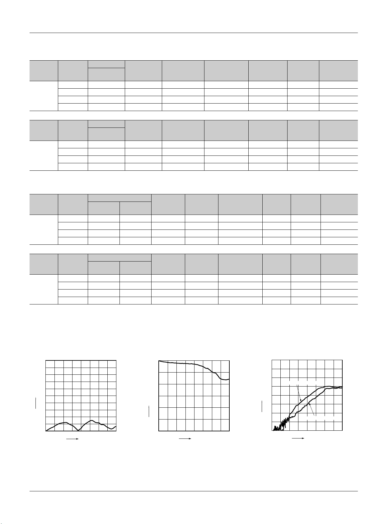
REFERENCE DATA
1. High frequency characteristics
Sample: ARJ20A12
Measuring method: Measured with MEW PC board by HP network analyzer (HP8510C).
• V.S.W.R. characteristics • Insertion loss characteristics
(without D.U.T. board’s loss)
2.0
1.9
1.8
1.7
1.6
V.S.W.R.
1.5
1.4
1.3
1.2
1.1
1.0
45MHz 5GHz 8GHz
Frequency
0
0.5
1.0
1.5
Insertion loss, dB
2.0
2.5
3.0
Frequency
8GHz5GHz45MHz
• Isolation characteristics
0
10
20
Between contact sets
30
40
Isolation, dB
50
60
70
80
45MHz 8GHz5GHz
Between open contact
Frequency
3
Page 3

RJ(ARJ2)
NONC
Com
Com
59
2
87106
3
4
1
+
–
Direction
indication
DIMENSIONS
1. Standard PC board terminal
10.4
.409
3.50
.138
0.50
.020
6.36
.250
0.20
.008
10.6
.417
12.2
.480
14.0
.551
8.89
.350
12.70
.500
11.40
.449
Expansion of A
0 to 0.2
0 to .008
(Typical: 0.1)
(Typical: .004)
24 ribs should be soldered with PC board ground.
9.00
0.40
.016
.354
A
7.62
0.20
.008
0.15
.006
.300
0.50
.020
1All bottom surface of the base should be
touched closely or soldered with PC board
ground.
3Better HF characteristics
may be obtained when this
8.20
portion is soldered with
.323
PC board ground.
0.50
.020
3.81
.150
General tolerance: ±0.3 ±.012
Schematic (Bottom view)
Single side stable
(Deenergized condition)
2 coil latching
Com
1103
2
7
8
Com
–
4
5
6
–
+
9
+
(Reset condition)
mm inch
NONC
2. Surface mount terminal
10.4
.409
6.36
.250
0.50
.020
0.40
.016
0.50
.020
10.6
.417
8.89
.350
12.2
.480
14.0
.551
15.0
.591
11.40
.449
Expansion of A
0 to 0.2
3.81
.150
24 ribs should be soldered with PC board ground.
9.00
.354
A
0.20
.008
10.0
.394
0.50
.020
1All bottom surface of the base should be
touched closely or soldered with PC board
ground.
0 to .008
(Typical: 0.1)
(Typical: .004)
3Better HF characteristics
may be obtained when this
8.20
portion is soldered with
.323
PC board ground.
General tolerance: ±0.3 ±.012
Schematic (Top view)
Single side stable
Direction
indication
(Deenergized condition)
87106
1
+
Com
2
Com
3
–
2 coil latching
Com
7
8
2
1103
Com
–
6
5
NONC
4
–
+
59
NONC
4
9
+
(Reset condition)
4
Page 4

B
1.0mm .039inch
A: Surface of PC board where relay is mounted.
B: Above the PC board surface.
A
NOTES
1. Coil operating power
Pure DC current should be applied to the
coil. The wav e form should be rectangular.
If it includes ripple, the ripple factor should
be less than 5%.
However, check it with the actual circuit
since the characteristics may be slightly
different. The nominal operating voltage
should be applied to the coil for more than
20 ms to set/reset the latching type relay.
2. Coil connection
When connecting coils, refer to the wiring
diagram to prevent mis-operation or malfunction.
3. External magnetic field
Since RJ relays are highly sensitive polarized relays, their characteristics will be affected by a strong e xternal magnetic field.
Avoid using the rela y under that condition.
4. Cleaning
For automatic cleaning, the boiling method is recommended. Avoid ultrasonic
cleaning which subjects the relays to high
frequency vibrations, which may cause
the contacts to stick.
It is recommended that alcoholic solvents
be used.
5. Tape and reel packing
1) T ape dimensions
1.50
.059
16.00
+0.1
0
+.004
.630
0
dia.
dia.
1.20
.441
3 to 5°
2) Dimensions of plastic reel
2.0±0.5
.079±.020
4.00 .157
2.0
(Accumulation 10 pitch:
.079
40±0.1 1.575±.004)
6.20
.244
11.40
.449
9.40
.370
1.33
.052
2.57
.101
21±0.8 dia.
.827±.031 dia.
.512±.008 dia.
1.75
.069
11.50
.453
(10.75)
(.423)
13±0.2 dia.
24.4
.961
0.40±0.05
.016±.002
24.00
.945
+2
0
+.079
0
16.00
.630
8.80
.346
8.50
.337
7.40
.291
1.50
3 to 5°
.059
14.40
.570
100±1 dia.
3.937±.039 dia.
370±2 dia.
14.567±.079 dia.
2.0±0.2
.079±.008
6. Conditions for operation, transport
and storage conditions
1) Ambient temperature, humidity, and atmospheric pressure during usage, transport, and storage of the relay:
(1) T emper ature:
–30 to +70°C –22 to +158°F
(However, tolerance range is –30 to
+60°C –22 to +140°F if package is carried
as is.)
(2) Humidity: 5 to 85% RH
(Avoid freezing and condensation.)
The humidity range varies with the temperature. Use within the range indicated
in the graph below.
(3) Atmospheric pressure: 86 to 106 kPa
Temperature and humidity range for usage, transport, and storage:
Humidity, %R.H.
85
Tolerance range
(Avoid freezing
when used at
temperatures
lower than
0°C 32°F)
–30
–22
(Avoid
condensation
when used at
temperatures
higher than
0°C 32°F)
5
0
32
Temperature, °C °F
70
158
2) Condensation
Condensation forms when there is a sudden change in temperature under high
temperature and high humidity conditions.
Condensation will cause deterioration of
the relay insulation.
3) Freezing
Condensation or other moisture may
freeze on the relay when the temperature
is lower than 0°C 32°F. This causes prob-
lems such as sticking of movab le parts or
operational time lags.
4) Low temperature, low humidity en vironments
The plastic becomes brittle if the relay is
exposed to a low temperature, lo w humidity environment for long periods of time.
5) Storage procedures for surface-mount
terminal types
Since the relay is very sensitive to humidity, it is packed in humidity-free, hermetically sealed packaging. When storing the
relay, be careful of the following points:
(1) Be sure to use the relay immediately
after removing it from its sealed package.
(2) When storing the relay f or long periods
of time after removing it from its sealed
package, we recommend using a humidity-free bag with silica gel to prevent subjecting the relay to humidity.
Furthermore, if the relay is solder mounted when it has been subjected to excessive humidity , cr acks and leaks can occur .
Be sure to mount the relay under the required mounting conditions.
RJ(ARJ2)
7. Soldering
1) Surface-mount terminal
In case of automatic soldering, the following conditions should be observed
(1) Position of measuring temperature
(2) IR (infrared reflow) soldering method
A: B:
T5
T4
T3
T2
T1
t1 t3 t4 t5t2
1=150°C 302°F
T
2=160°C 320°F
T
3=183°C 361°F
T
4=245°C 473°F
T
5=270°C 518°F
T
Temperature rise of relay itself may vary
according to the mounting level or the
heating method of reflow equipment.
Therefore, please set the temperature of
soldering portion of relay terminal and the
top surface of the relay case not to e xceed
the above mentioned soldering condition.
It is recommended to check the temperature rise of each portion under actual
mounting condition before use.
2) Standard PC board terminal
Please meet the following conditions if
this relay is to be automatically soldered.
(1) Preheating: Max. 100°C 212°F (termi-
nal solder surface) for max. 60 seconds
(2) Soldering: Max. 250°C 482°F for max.
5 seconds
The effect on the relay depends on the actual substrate used. Please v erify the substrate to be used.
3) Hand soldering
Please meet the following conditions if
this relay is to be soldered by hand.
(1) Wattage: 30 to 60 W
(2) Tip temperature/time: 280 to 300°C
536 to 572°F for max. 5 seconds
The effect on the relay depends on the actual substrate used. Please v erify the substrate to be used.
4) Avoid high frequency cleaning since
this may adversely affect relay characteristics. Use alcohol-based cleaning solutions when cleaning relays.
t2 - t1 = 80 to 120 s
5 - t3 = 30 to 40 s
t
4 = 170 to 190 s
t
5
Page 5

RJ(ARJ2)
Measuring method (Impedance 50Ω)
1 2
B
Network
analyzer
HP 8510C HP 8515A
RF
OUT
B
S parameter
A
R
RF
IN
test set
A
R
Connector
No. Product name Contents
1 HP 85131-60013
2 HP 83059
(Step 1) Calibrate the test system with HP
calibration kit [HP85052B]
(Step 2) After calibration, connect the
D.U.T. board and measure. Connect 50 Ω terminals on connectors other than those for
measurement.
Notes)
1. All bottom surface of the base should be
touched closely or soldered with PC board
ground.
2. 4 ribs should be soldered with PC board
ground.
Measuring board
1) Dimensions
<Surface mount terminal>
6-1.76
6-.069
0.80
.031
7.07
.278
2.81
.111
0.40
.016
1.00
.039
20.00
.787
PORT2
PORT1
3.5 mm testport,
Extension cable
3.5 mm coaxial
adaptor
17.00
.669
0.40
.016
0.40
.016
0.40
.016
8.89
.350
12.04
.474
8.35
.329
30.00
1.181
1
7.22
.284
Through hole
86-0.40 dia.
86-.016 dia.
45°
<Standard PC board terminal>
4-1.60 dia.
4-.063 dia.
78-0.40 dia.
78-.016 dia.
2
7.62
.300
20.00
.787
3.81
.150
6-0.70 dia.
6-.028 dia.
6.62
.261
0.90
.035
0.50
.020
6-1.86
6-.073
8.35
.329
12.70
.500
17.00
.669
8.89
.350
11.70
.461
30.00
1.181
0.50
.020
0.40
.016
0.40
.016
<Calibration board>
14.5
.571
10.0
.394
0.40 or 0.50
.016 or .020
1.76 or 1.86
.069 or .073
2) Material: Glass PTFE double-sided
through hole PC board R-4737 (Matsushita Electric Works)
3) Board thickness: t = 0.8 mm
4) Copper plating: 18µm
• Connector (SMA type receptacle)
Product name: R125 510 (RADIALL)
Insertion loss compensation
The insertion loss of relay itself is given by
subtracting the insertion loss of shortcircuit the Com and the NC (or NO). (signal path and two connectors)
9. Others
1) The switching lifetime is defined under
the standard test condition specified in the
JIS* C 5442-1996 standard (temperature
15 to 35°C 59 to 95°F, humidity 25 to
75%). Chec k this with the real device as it
is affected by coil driving circuit, load type,
activation frequency, activation phase,
ambient conditions and other factors.
Also, be especially careful of loads such
as those listed below.
• When used for AC load-operating and
the operating phase is synchronous.
Rocking and fusing can easily occur due
to contact shifting.
4-0.60 dia.
4-.024 dia.
6-1.70 dia.
6-.067 dia.
1.00
.039
45°
6.72
.265
• High-frequency load-operating
When high-frequency opening and closing of the relay is performed with a load
that causes arcs at the contacts, nitrogen
and oxygen in the air is fused by the arc
energy and HNO
3
is formed. This can cor-
rode metal materials.
Three countermeasures for these are listed
here.
(1) Incorporate an arc-extinguishing circuit.
(2) Lower the operating frequency
(3) Lower the ambient humidity
2) Use the relay within specifications such
as coil rating, contact rating and on/off
service life. If used beyond limits, the rela y
may overheat, generate smoke or catch
fire.
3) Be careful not to drop the relay. If accidentally dropped, carefully check its appearance and characteristics before use.
4) Be careful to wire the relay correctly.
Otherwise, malfunction, overheat, fire or
other trouble may occur.
5) If a relay stays on in a circuit for many
months or years at a time without being
activated, circuit design should be reviewed so that the relay can remain nonexcited. A coil that receives current all the
time heats, which degrades insulation
earlier than expected. A latching type relay is recommended for such circuits.
6) The latching type rela y is shipped in the
reset position. But jolts during transport or
impacts during installation can change
the reset position. It is, therefore, advisable to build a circuit in which the relay
can be initialized (set and reset) just after
turning on the power.
7) If silicone materials (e.g., silicone rubbers, silicone oils, silicone coating agents,
silicone sealers) are used in the vicinity of
the relay , the gas emitted from the silicone
may adhere to the contacts of the relay
during opening and closing and lead to
improper contact. If this is the case , use a
material other than silicone.
8) We recommend latching type when using in applications which involve lengthy
duty cycles.
* Japanese Industrial Standards
12/2/2002 All Rights Reserved, © Copyright Matsushita Electric Works, Ltd.
16
Go To Online Catalog
 Loading...