

Page 1
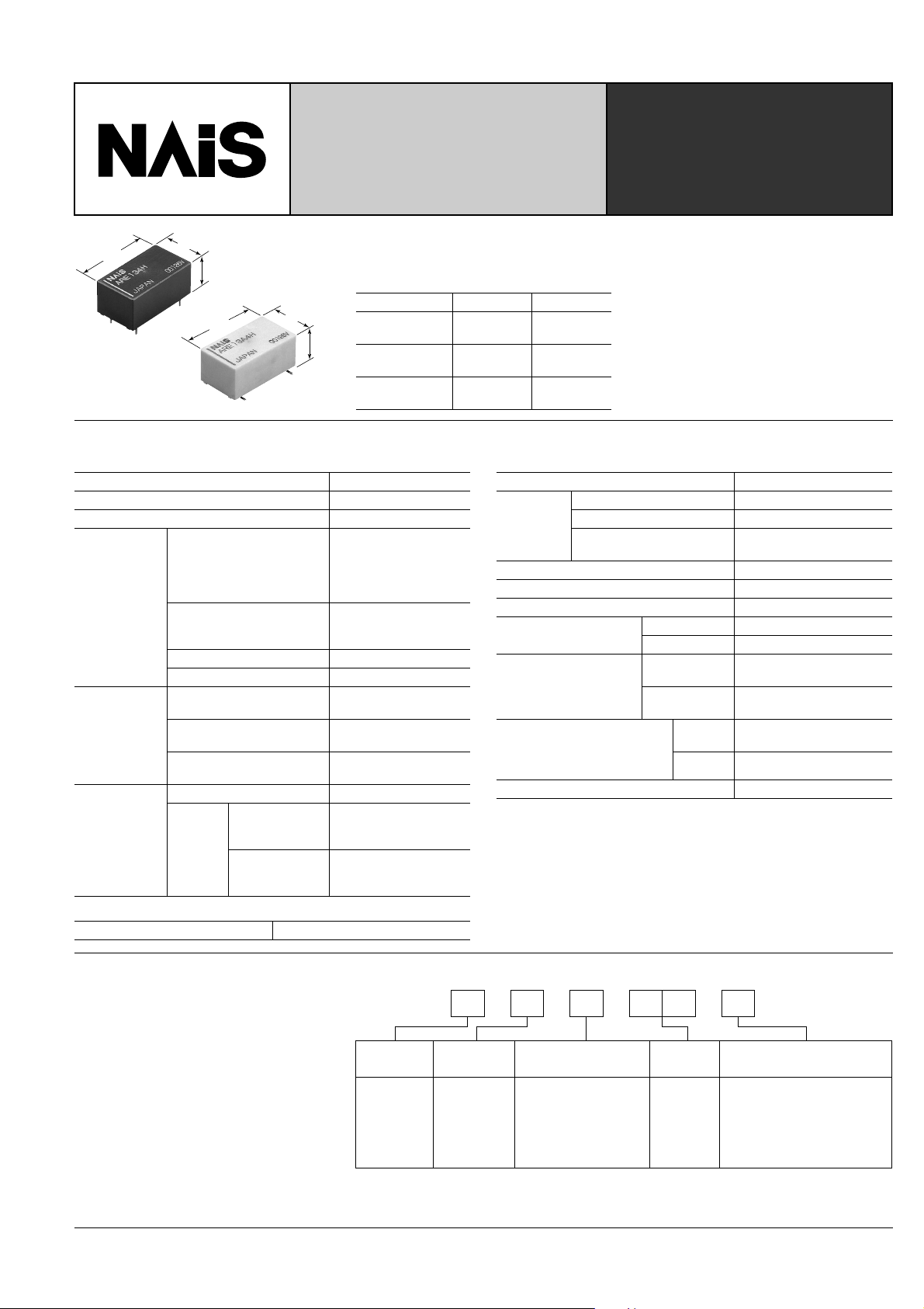
2.6 GHz 75Ω RELAYS FOR
BROADCASTING INDUSTRY
RE-RELAYS
20.2
.795
11.2
.441
8.9
.350
20.2
.795
11.2
.441
FEATURES
• Excellent high frequency characteristics (Impedance 75Ω)
Frequency 900MHz 2.6GHz
V.S.W.R.
9.6
.378
(Max.)
Insertion loss
(dB, Max.)
Isolation
mm inch
(dB, Min.)
SPECIFICATIONS
Contact
Arrangement 1 Form C
Contact material Gold
Initial contact resistance Max. 100m
Contact rating
75 Ω, V .S.W .R. Max.1.5)
Rating
Contact carrying power
Max. switching voltage 30 V DC
Max. switching current 0.5 A DC
(at 2.6 GHz, Impedance
Max. 1.2 (to 900MHz)
Max. 1.5 (to 2.6GHz)
Max. 0.2 (to 900MHz)
Max. 0.5 (to 2.6GHz)
Min. 60dB (to 900MHz)
Min. 30dB (to 2.6GHz)
High frequency
characteristics
(Impedance
75Ω)
V.S.W.R.
Insertion loss
Isolation
Mechanical (at 180 cpm) 10
1W, 2.6GHz,
Expected life
(min. operations)
Electrical
Impedance 75Ω,
V.S.W.R. & 1.5
10mA 24V DC
(resistive load)
(at 20cpm)
Coil (at 20°C, 68°F)
Nominal operating power 200 mW
1W
10mA 24V DC
(resistive load)
10W (at 2.6GHz,
Impedance 75 Ω,
V.S.W.R. Max.1.5)
3×10
3×10
• Surface-mount terminal type also
available
1.2 1.5
0.2 0.5
60 30
Characteristics
Initial insulation resistance*
Ω
Initial
breakdown
voltage*
Between open contacts 500 Vrms
Between contact and coil 1,000 Vrms
2
Between contact and
ground terminal
1
Operate time*3 (at 20°C) Max. 10ms
Release time (without diode)*3 (at 20°C) Max. 5ms
Temperature rise (at 20°C)*
Shock resistance
4
Functional*
Destructive*
Functional*
Vibration resistance
Destructive
Conditions for operation,
transport and storage*8
(Not freezing and condensing
at low temperature)
6
Unit weight Approx. 5 g .18 oz
Ambient
temp.
Humidity 5 to 85% R.H.
Remarks
5
5
* Specifications will vary with foreign standards certification ratings.
1
Measurement at same location as "Initial breakdown voltage" section.
*
*2Detection current: 10mA
*3Nominal operating voltage applied to the coil, excluding contact bounce time.
4
By resistive method, nominal voltage applied to the coil: Contact carrying power:
*
10W, at 2.6GHz, Impedance 75Ω, V .S.W.R. & 1.5
5
Half-wave pulse of sine wave: 11ms, detection time: 10µs.
*
*6Half-wave pulse of sine wave: 6ms
7
Detection time: 10µs
*
*8Refer to 5. Conditions for operation, transport and storage mentioned in NOTES
Min. 100 MΩ (at 500 V DC)
500 Vrms
Max. 60°C
5
7
Min. 500 m/s2{50 G}
6
Min. 1,000 m/s2{100 G}
10 to 55 Hz at double
amplitude of 3 mm
10 to 55 Hz at double
amplitude of 5 mm
–40°C to 60°C
–40°F to 140°F
TYPICAL APPLICATIONS
Broadcasting market
• Set Top Box (CS/BS tuner, CATV tuner)
• Multi-function TV
• Measuring instruments for broadcasting
ORDERING INFORMATION
Ex.
ARE 1 3
Contact
arrangement
1: 1 Form C 3: Single side
Note: Tape and reel packing symbol “-Z” is not marked on the relay.
“X type tape and reel packing (picked from 8/9/10/11/12/13/14-pin side) is also availabe.
Suffix “X” instead of “Z”.
Operating
function
stable type
Terminal shape
Nil:A:Standard PC board
terminal
Surface-mount
terminal
Coil voltage
(DC)
03: 3 V
4H: 4.5 V
06: 6 V
09: 9 V
12: 12 V
24: 24 V
Packing style
Nil:Z:Carton (PC board terminal)
Tube (Surface-mount
terminal)
Tape and reel packing
(picked from 1/7 pin side)
77
Page 2
RE
TYPES AND COIL DATA (at 20°C 68°F)
• Packing of standard PC board terminal: 50 pcs. in an inner package (carton); 500 pcs. in an outer package
• Packing of surface-mount terminal: 25 pcs. in an inner package (tube); 200 pcs. in an outer package
400 pcs. in an inner package (tape and reel); 800 pcs. in an outer package
Standard
PC board
terminal
Surface-mount
terminal
ARE1303 ARE13A03 3 2.25 0.3 45 66.7 200 3.3
ARE134H ARE13A4H 4.5 3.375 0.45 101 44.4 200 4.95
ARE1306 ARE13A06 6 4.5 0.6 180 33.3 200 6.6
ARE1309 ARE13A09 9 6.75 0.9 405 22.2 200 9.9
ARE1312 ARE13A12 12 9 1.2 720 16.7 200 13.2
ARE1324 ARE13A24 24 18 2.4 2,880 8.3 200 26.4
Nominal
voltage,
V DC
Pick-up voltage,
V DC (max.)
(initial)
Drop-out
voltage, V DC
(min.)(initial)
Coil resistance,
Ω (±
10%)
Nominal
operating current,
mA (±10%)
Nominal oper-
ating power,
mW
Max. allowable
voltage, V DC
DIMENSIONS
1. Standard PC board terminal
2. Surface mount terminal
13.2
.520
±0.5
±.020
11.2
.441
8.6
.339
0.3
.012
(0.7)
(.028)
11.2
.441
(1.3)
(.511)
8.6
.339
2.54
.100
20.2
.795
20.2
.795
0.5
.020
3.0
.118
0.3
.012
(1.49)
7.62
(.059)
.300
General tolerance: ±0.3 ±.012
0.3
.012
0.3
.012
(2.09)
(.082)
0.3
.012
9.6
.378
Stand off
Schematic (Bottom view)
Direction indication
(Deenergized condition)
NC
Schematic (Top view)
Direction indication
(Deenergized condition)
mm inch
71
COM NO
17
891011121314
NOCOMNC
811 10 9121314
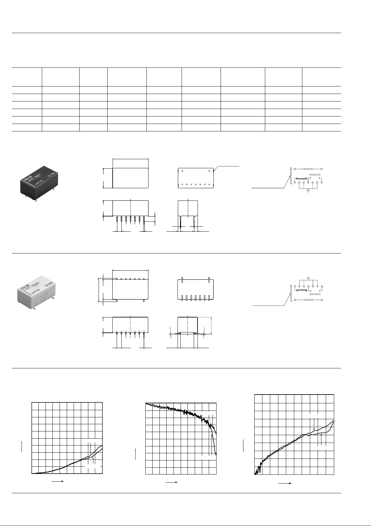
REFERENCE DATA
1. High frequency characteristics
(Standard PC board terminal)
• V .S.W.R. characteristics
2.0
1.9
1.8
1.7
1.6
1.5
78
V.S.W.R.
1.4
1.3
1.2
1.1
1
900MHz
Frequency
COM-NO
COM-NC
0.3
.012
3GHz
2.54
.100
0.5
.020
(1.49)
(.059)
7.62
.300
(2.09)
(.082)
General tolerance: ±0.3 ±.012
• Insertion loss characteristics • Isolation characteristics
0
0
0.1
0.2
0.3
0.4
0.5
Insertion loss, dB
0.6
0.7
0.8
0.9
1.0
900MHz
COM-NC
COM-NO
3GHz
Frequency
10
20
30
40
50
Isolation, dB
60
70
80
90
100
900MHz
COM-NC
COM-NO
3GHz
Frequency
Page 3

NOTES
(Avoid
condensation
when used at
temperatures
higher than
0°C32°F)
Temperature, °C °F
Humidity, %R.H.
85
5
0
+32
+60
+140
–40
–40
Tolerance range
(Avoid freezing
when used at
temperatures
lower than
0°C32°F)
1. Coil operating power
Pure DC current should be applied to the
coil. The wav e form should be rectangular.
If it includes ripple, the ripple factor should
be less than 5%.
However, check it with the actual circuit
since the characteristics may be slightly
different.
2. Cleaning
For automatic cleaning, the boiling method is recommended. Avoid ultrasonic
cleaning which subjects the relays to high
frequency vibrations, which may cause
the contacts to stick.
It is recommended that alcoholic solvents
be used.
3. Soldering
1) The soldering shall be performed under
following condition.
Max. 260°C 500°F 10s
Max. 350°C 662°F 3s
The affect of the PCB on the relay will differ depending on the type of PCB used.
Please verify the type of PCB to be used.
Soldering time: within 5s
2) In case of automatic soldering, the following conditions should be observed
(Surface-mount terminal)
(1) Position of measuring temperature
1.0mm .039inch
A: Surface of PC board where relay is mounted.
B: Above the PC board surface.
B
A
(2) IR (infrared reflow) soldering method
A: B:
T5
T4
T3
T2
T1
t1 t3 t4 t5t2
1=150°C 302°F
T
2=160°C 320°F
T
3=183°C 361°F
T
4=245°C 473°F
T
5=270°C 518°F
T
t2 - t1 = 80 to 120 s
5 - t3 = 30 to 40 s
t
4 = 170 to 190 s
t
Temperature rise of relay itself may vary
according to the mounting level or the
heating method of reflow equipment.
Therefore, please set the temperature of
soldering portion of relay terminal and the
top surface of the relay case not to e xceed
the above mentioned soldering condition.
It is recommended to check the temperature rise of each portion under actual
mounting condition before use.
4. Packing style
1) T ape dimensions
+0.1
+.004
−0 dia..059
−0
Relay polarity bar
1.7
.067
R0.75
.030
1.5 .059
1.5
RE Relay
Tape coming out direction
.157
20.0
.787
4
2.0
.079
1.75
±0.15
±.006
20.75
.817
13.85
.545
.069
20.2
.795
40.4
1.591
44
1.732
.016
±0.3
0.4
±.012
+0.2
10.6
−0.3
+.008
.417
−.012
2) Dimensions of plastic reel
±0.8
21
dia.
±.031
.827
dia.
380
14.961
±0.2
±.008
.079
±0.1
80
±.004
3.150
±0.2
13
dia.
±.008
.512
±0.5
2.0
±.020
dia.
44.4
1.748
Max. 50.5
1.988
+0.2
−0
+.008
−0
5. Conditions for operation, transport
and storage
1) Ambient temperature, humidity, and atmospheric pressure during usage, transport, and storage of the relay:
(1) T emper ature:
–40 to +60°C –40 to +140°F
(2) Humidity: 5 to 85% RH
(Avoid freezing and condensation.)
The humidity range varies with the temperature. Use within the range indicated
in the graph below.
(3) Atmospheric pressure: 86 to 106 kPa
Temperature and humidity range for usage, transport, and storage:
2) Condensation
Condensation forms when there is a sudden change in temperature under high
temperature and high humidity conditions.
Condensation will cause deterioration of
the relay insulation.
3) Freezing
Condensation or other moisture may
freeze on the relay when the temperature
is lower than 0°C 32°F. This causes problems such as sticking of movab le parts or
operational time lags.
4) Low temperature, low humidity en vironments
The plastic becomes brittle if the relay is
exposed to a low temperature, lo w humidity environment for long periods of time.
RE
For Cautions for Use, see Relay Technical Information (Page 48 to 76).
3/7/2002 All Rights Reserved, © Copyright Matsushita Electric Works, Ltd.
Go To Online Catalog
79
 Loading...