

Page 1
1 3
2
1-Anode 1
2-Common Cathode
Back of Case -Cathode
3-Anode 2
1
TO-264
APT60D60LCT 600V 2x60A
3
2
ULTRAFAST SOFT RECOVERY RECTIFIER DIODES
PRODUCT APPLICATIONS
• Parallel Diode
PRODUCT FEATURES
• Ultrafast Recovery Times
-Switchmode Power Supply
-Inverters
• Free Wheeling Diode
-Motor Controllers
-Converters
• Snubber Diode
• Uninterruptible Power Supply (UPS)
• Soft Recovery Characteristics
• Popular TO-264 Package
• Low Forward Voltage
• High Blocking Voltage
• Induction Heating
• High Speed Rectifiers
• Low Leakage Current
MAXIMUM RATINGS All Ratings Are Per Leg: TC = 25°C unless otherwise specified.
Symbol
Characteristic / Test Conditions
PRODUCT BENEFITS
• Low Losses
• Low Noise Switching
• Cooler Operation
• Higher Reliability Systems
• Increased System Power
Density
APT60D60LCT
UNIT
V
V
RRM
V
RWM
IF(AV)
(RMS)
I
F
I
FSM
TJ,T
T
Maximum D.C. Reverse Voltage
R
Maximum Peak Repetitive Reverse Voltage
Maximum Working Peak Reverse Voltage
Maximum Average Forward Current (T
RMS Forward Current
Non-Repetitive Forward Surge Current (TJ = 45°C, 8.3ms)
Operating and StorageTemperature Range
STG
Lead Temperature: 0.063" from Case for 10 Sec.
L
STATIC ELECTRICAL CHARACTERISTICS
Symbol
V
I
RM
Characteristic / Test Conditions
Maximum Forward Voltage I
F
Maximum Reverse Leakage Current VR = VR Rated
= 70°C, Duty Cycle = 0.5)
C
I
= 60A
F
= 120A
F
IF = 60A, TJ = 150°C
VR = VR Rated, TJ = 125°C
600
60
100
600
-55 to 150
300
MIN TYP MAX
1.8
1.75
1.5
250
500
Volts
Amps
°C
UNIT
Volts
µA
C
L
USA
405 S.W. Columbia Street Bend, Oregon 97702-1035 Phone: (541) 382-8028 FAX: (541) 388-0364
EUROPE
Avenue J.F. Kennedy Bât B4 Parc Cadéra Nord F-33700 Merignac - France Phone: (33) 5 5792 15 15 FAX: (33) 5 56 47 97 61
Junction Capacitance, V
T
Series Inductance (Lead to Lead 5mm from Base)
S
= 200V
R
APT Website - http://www.advancedpower.com
85
10
pF
nH
053-6017 Rev -
Page 2
DYNAMIC CHARACTERISTICS
APT60D60LCT
Symbol
t
rr1
t
rr2
t
rr3
t
fr1
t
fr2
I
RRM1
I
RRM2
Q
rr1
Q
rr2
V
fr1
V
fr2
diM/dt
Characteristic
Reverse Recovery Time, I
= 1.0A, diF/dt = -15A/µs, VR = 30V, TJ = 25°C
F
Reverse Recovery Time TJ = 25°C
= 60A, diF/dt = -480A/µs, VR = 350V TJ = 100°C
I
F
Forward Recovery Time TJ = 25°C
= 60A, diF/dt = 480A/µs, VR = 350V TJ = 100°C
I
F
Reverse Recovery Current TJ = 25°C
= 60A, diF/dt = -480A/µs, VR = 350V TJ = 100°C
I
F
Recovery Charge T
= 25°C
J
IF = 60A, diF/dt = -480A/µs, VR = 350V TJ = 100°C
Forward Recovery Voltage T
= 60A, diF/dt = 480A/µs, VR = 350V TJ = 100°C
I
F
= 25°C
J
Rate of Fall of Recovery Current TJ = 25°C
= 60A, diF/dt = -480A/µs, VR = 350V (See Figure 10) TJ = 100°C
I
F
MIN TYP MAX
55 70
70
90
160
160
10 17
20 30
350
900
6
6
800
500
UNIT
ns
Amps
nC
Volts
A/µs
THERMAL AND MECHANICAL CHARACTERISTICS
θJC
θJA
1.0
0.5
0.1
Characteristic / Test Conditions
Junction-to-Case Thermal Resistance
Junction-to-Ambient Thermal Resistance
Package Weight
T
Maximum Mounting Torque (Screw Type = 6-32 or 3mm Machine)
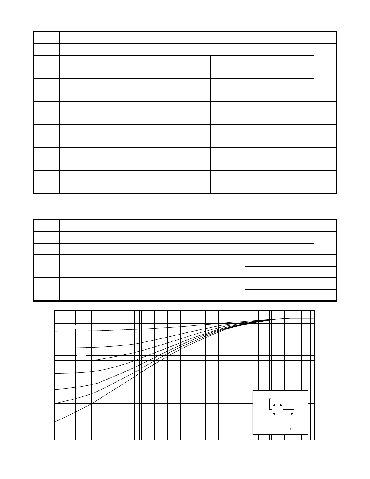
D=0.5
0.2
0.1
0.05
0.02
0.01
SINGLE PULSE
Symbol
R
R
W
Torque
0.05
0.01
, THERMAL IMPEDANCE (°C/W)
JC
θ
0.005
Z
MIN TYP MAX
0.66
40
0.22
6.1
10
1.1
NOTE:
DM
t
1
P
t
2
/
DUTY FACTOR D=t
=+
PEAK T P x Z T
DM JC
t
12
UNIT
°C/W
oz
gm
lb•in
N•m
CJ
0.001
053-6017 Rev -
-5
10
FIGURE 1, MAXIMUM EFFECTIVE TRANSIENT THERMAL IMPEDANCE, JUNCTION-TO-CASE vs PULSE DURATION
-4
10
-3
10
RECTANGULAR PULSE DURATION (SECONDS)
-2
10
10
-1
1.0 10
Page 3

APT60D60LCT
200
160
2500
2000
TJ=100°C
VR=350V
120
80
, FORWARD CURRENT
F
40
0
0 0.5 1.0 1.5 2.0 2.5 10 50 100 500 1000
VF, ANODE-TO-CATHODE VOLTAGE (VOLTS) diF/dt, CURRENT SLEW RATE (AMPERES/µSEC)
TJ = 150°C
TJ = 100°C
TJ = 25°C
= -55°C
T
J
1500
1000
500
, REVERSE RECOVERY CHARGE
rr
0
120A
60A
30A
Figure 2, Forward Voltage Drop vs Forward Current Figure 3, Reverse Recovery Charge vs Current Slew Rate
50
TJ=100°C
VR=350V
40
120A
60A
30
2.0
1.6
1.2
Q
rr
t
rr
30A
t
RRM
rr
Q
rr
, REVERSE RECOVERY CURRENT I
RRM
20
10
0
0 200 400 600 800 1000 -50 -25 0 25 50 75 100 125 150
di
/dt, CURRENT SLEW RATE (AMPERES/µSEC) TJ, JUNCTION TEMPERATURE (°C)
F
0.8
, DYNAMIC PARAMETERS Q
f
0.4
0.0
I
Figure 4, Reverse Recovery Current vs Current Slew Rate Figure 5, Dynamic Parameters vs Junction Temperature
200
160
120
TJ=100°C
VR=350V
120A
60A
30A
1200
1000
800
600
TJ=100°C
VR=350V
IF=60A
V
fr
15.0
12.5
10.0
7.5
80
400
(nano-SECONDS) (NORMALIZED) (nano-COULOMBS)
40
, REVERSE RECOVERY TIME I
rr
0
0 200 400 600 800 1000 0 200 400 600 800 1000
diF/dt, CURRENT SLEW RATE (AMPERES/µSEC) diF/dt, CURRENT SLEW RATE (AMPERES/µSEC)
, FORWARD RECOVERY TIME K
200
fr
t
T
fr
0
5.0
2.5
0
Figure 6, Reverse Recovery Time vs Current Slew Rate Figure 7, Forward Recovery Voltage/Time vs Current Slew Rate
2000
(VOLTS)
, FORWARD RECOVERY VOLTAGE
fr
V
1000
500
(pico-FARADS) (nano-SECONDS) (AMPERES) (AMPERES)
, JUNCTION CAPACITANCE t
100
J
C
50
0.01 0.05 0.1 0.5 1 5 10 50 100 200
Figure 8, Junction Capacitance vs Reverse Voltage
V
, REVERSE VOLTAGE (VOLTS)
R
053-6017 Rev -
Page 4

30µH
V
r
APT60D60LCT
D.U.T.
t
Q
/
rr
rr
Waveform
+15v
diF/dt Adjust
0v
-15v
Figure 9, Diode Reverse Recovery Test Circuit and Waveforms
1
- Forward Conduction Current
I
F
2
/dt - Current Slew Rate, Rate of Forward
di
F
Current Change Through Zero Crossing.
1
Zero
3
4
5
6
- Peak Reverse Recovery Current.
I
RRM
trr - Reverse Recovery Time Measured from Point of I
Current Falling Through Zero to a Tangent Line
Extrapolated Through Zero Defined by 0.75 and 0.50 I
Qrr - Area Under the Curve Defined by I
RRM
and trr.
F
6
{
diM/dt
RRM
}
.
diM/dt - Maximum Rate of Current Change During the Trailing Portion of t
Figure 10, Diode Reverse Recovery Waveform and Definitions
PEARSON 411
CURRENT
TRANSFORMER
3
2
rr.
4
6
5
0.5 I
RRM
0.75 I
RRM
Q
rr
= 1/
t
I
(
rr
2
)
RRM
.
4.60 (.181)
5.21 (.205)
1.80 (.071)
2.01 (.079)
Common Cathode
0.48 (.019)
0.84 (.033)
2.59 (.102)
3.00 (.118)
TO-264 Package Outline
19.51 (.768)
20.50 (.807)
5.79 (.228)
6.20 (.244)
25.48 (1.003)
26.49 (1.043)
2.29 (.090)
2.69 (.106)
19.81 (.780)
21.39 (.842)
0.76 (.030)
1.30 (.051)
2.79 (.110)
3.18 (.125)
5.45 (.215) BSC
Dimensions in Millimeters and (Inches)
2-Plcs.
3.10 (.122)
3.48 (.137)
2.29 (.090)
2.69 (.106)
Anode 1
Common Cathode
Anode 2
APT Reserves the right to change, without notice, the specifications and information contained herein.
053-6017 Rev -
 Loading...