

Page 1
Alpha Industries, Inc. [781] 241-7000 • Fax [978] 241-7906 • Email sales@alphaind.com • www.alphaind.com 1
Specifications subject to change without notice. 12/01A
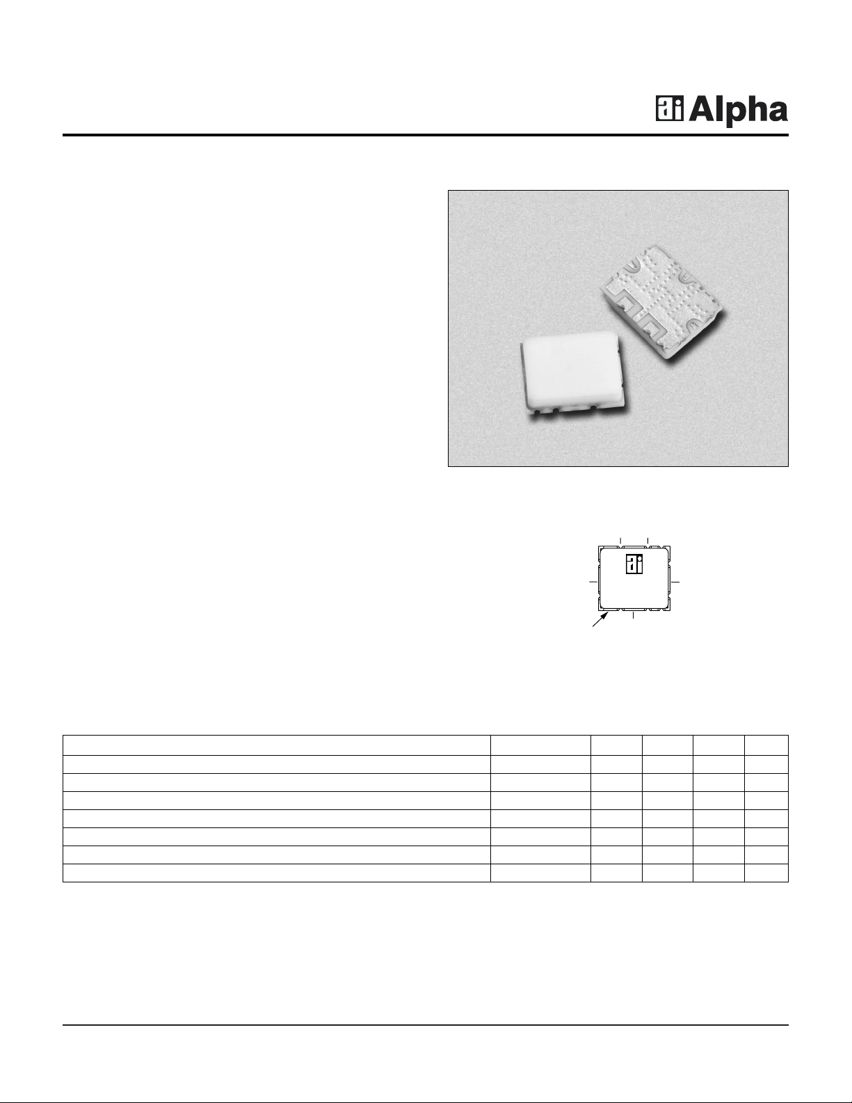
23–34 GHz Surface Mount
SPDT Switch
Features
■ Surface Mount Package
■ Low Loss, 1.3 dB
■ High Isolation, 33 dB
■ High Power Handling, +33 dBm CW
■ Fast Switching Speed, 2 nS
■ 100% RF and DC Testing
AP640R5-A3
Patent Pending
Description
The AP640R5-A3 is a broadband millimeterwave singlepole double-throw (SPDT) switch in a rugged surface
mount package which is compatible with high-volume
solder installation. Based on PIN diode MMIC technology,
the switch is designed for use in millimeterwave
communication and sensor systems when low loss and
high linearity are required. Typical applications are
transmit/receive function for TDD systems or switching
between signal paths.The robust ceramic surface mount
package provides excellent electrical performance and a
high degree of environmental protection for long-term
reliability. All switches are screened at the operating
frequencies prior to shipment for guaranteed
performance. Switch is targeted for high-volume
broadband applications such as satellite and fixed wireless
systems.
Pin Out
AP640R5-A3
YYWW
J
1
Orientation
Indicated by
Missing
Castellations
J
3
J
2
B
2
B
1
Preliminary
Parameter Symbol Min. Typ. Max. Unit
Operating Bandwidth BW 23 34 GHz
Insertion Loss IL 1.3 2 dB
Isolation ISO 28 33 dBm
Return Loss RL 9 dB
Leakage Current @ VR= -50 V I
DD
110µA
Switching Speed
1
t
switch
2ns
Output Power at 1 dB Compression
1
P
1 dB
33 dBm
Electrical Specifications at 25°C
1. Not measured on a 100% basis.
Page 2
23–34 GHz Surface Mount SPDT Switch AP640R5-A3
2 Alpha Industries, Inc. [781] 241-7000 • Fax [978] 241-7906 • Email sales@alphaind.com • www.alphaind.com
Specifications subject to change without notice. 12/01A
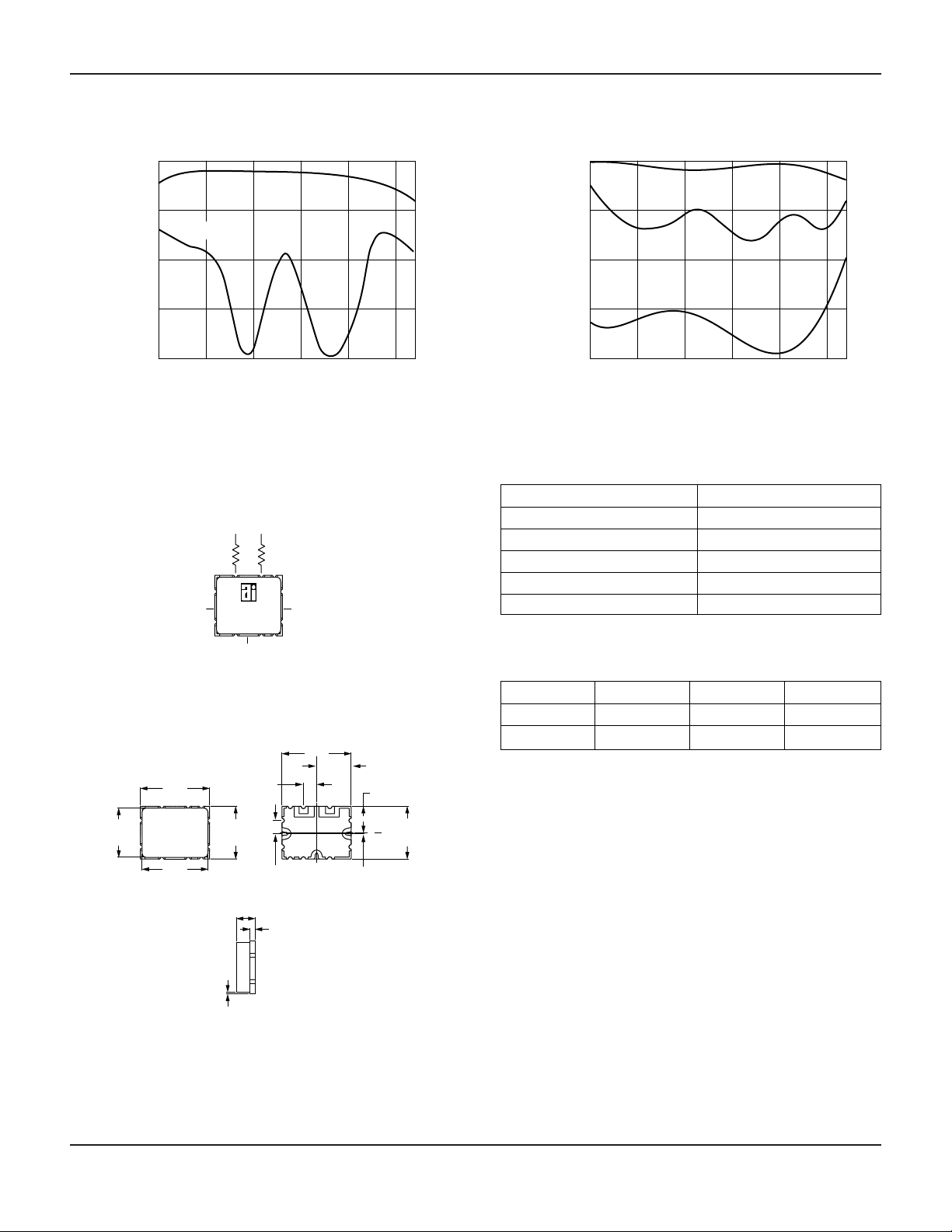
Frequency (GHz)
Insertion Loss vs. Frequency
Insertion Loss (dB)
-20
-15
-10
-5
0
18 23 28 33
S
21
38 43
S11 & S
22
Frequency (GHz)
Isolation vs. Frequency
Isolation (dB)
-40
-30
-20
-10
0
18 23 28 33 38 43
S
21
S
11
S
22
Typical Performance Data
Outline
0.005 (0.13 mm)
0.057 (1.45 mm)
J
1
0.040
(1.02 mm)
TYP.
0.105
(2.67 mm)
0.210 (5.33 mm)
J
2
0.040
(1.02 mm)
0.016 ± 0.002
(0.41 mm)
B
2
B
1
J
3
C
L
0.160
(4.06 mm)
0.003
(0.08 mm)
0.200 (5.08 mm)
0.210 (5.33 mm)
0.160
(4.06 mm)
0.150
(3.81 mm)
0.080
(2.03 mm)
Characteristic Value
Operating Temperature (TC) -55°C to +85°C
Storage Temperature (TST) -65°C to +125°C
DC Reverse Bias (VBR) -70 V (-10 mA)
DC Forward Bias (VBF) +1.3 V (50 mA)
Input Power (PIN) +40 dBm
Absolute Maximum Ratings
B
1
B
2
J1–J
2
J1–J
3
+10 mA -5 V Insertion Loss Isolation
-5 V +10 mA Isolation Insertion Loss
Truth Table
Bias Arrangement
AP640R5-A3
External
Resistors
YYWW
J
1
RF
J3 RF
J
2
RF
B
2
DC “Off”
+10 mA
(~1.25 V)
B
1
DC “On”
-5 V
(~1 µA)
Page 3

23–34 GHz Surface Mount SPDT Switch AP640R5-A3
Alpha Industries, Inc. [781] 241-7000 • Fax [978] 241-7906 • Email sales@alphaind.com • www.alphaind.com 3
Specifications subject to change without notice. 12/01A
Typical S-Parameters — Insertion Loss
Frequency
S
11
S
21
S
12
S
22
(GHz) Mag. (dB) Ang. (Deg.) Mag. (dB) Ang. (Deg.) Mag. (dB) Ang. (Deg.) Mag. (dB) Ang. (Deg.)
18 -6.5 144 -2.28 45 -2.28 45 -7.4 151
20 -10.2 -155 -1.11 -18 -1.11 -18 -11.5 -79
21 -8.3 -167 -1.23 -43 -1.23 -43 -8.5 -96
22 -11.7 160 -1.20 -66 -1.20 -66 -9.7 -95
23 -13.2 76 -1.15 -90 -1.15 -90 -10.1 -77
24 -10.7 24 -1.16 -114 -1.16 -114 -9.7 -77
25 -12.0 -3 -0.94 -139 -0.94 -139 -12.4 -93
26 -17.8 -26 -0.72 -165 -0.72 -165 -20.7 -104
27 -32.1 52 -0.83 168 -0.83 168 -30.5 -50
28 -25.4 167 -0.82 145 -0.82 144 -24.6 -78
29 -15.0 162 -1.01 120 -1.01 119 -15.5 -111
30 -10.2 145 -1.37 95 -1.37 95 -10.8 -133
31 -9.0 123 -1.48 74 -1.48 73 -10.0 -154
32 -10.8 95 -1.45 52 -1.45 52 -10.9 -176
33 -13.5 59 -1.42 30 -1.42 29 -11.5 154
34 -14.9 20 -0.94 4 -0.94 4 -13.7 126
35 -22.4 -13 -0.93 -23 -0.93 -23 -22.9 126
36 -29.3 141 -0.91 -51 -0.91 -51 -19.9 -113
38 -21.4 88 -1.41 -108 -1.41 -108 -19.3 -90
40 -12.4 179 -2.87 -161 -2.87 -161 -7.8 -44
42 -9.5 123 -2.25 154 -2.25 154 -8.3 -18
44 -14.9 -84 -2.99 87 -2.99 86 -9.4 12
45 -9.6 -156 -4.34 51 -4.34 51 -16.3 83
Page 4

23–34 GHz Surface Mount SPDT Switch AP640R5-A3
4 Alpha Industries, Inc. [781] 241-7000 • Fax [978] 241-7906 • Email sales@alphaind.com • www.alphaind.com
Specifications subject to change without notice. 12/01A
Typical S-Parameters — Isolation
Frequency
S
11
S
21
S
12
S
22
(GHz) Mag. (dB) Ang. (Deg.) Mag. (dB) Ang. (Deg.) Mag. (dB) Ang. (Deg.) Mag. (dB) Ang. (Deg.)
18 -7.1 154 -31.7 -4 -31.7 -4 -0.3 -119
20 -8.9 -177 -35.6 -52 -35.6 -52 -0.2 -137
21 -10.6 176 -37.5 -45 -37.6 -45 -0.3 -144
22 -19.2 161 -28.8 -64 -28.9 -64 -0.5 -152
23 -27.5 43 -28.9 -107 -28.9 -107 -0.6 -170
24 -17.3 50 -29.5 -139 -29.4 -139 -0.7 163
25 -12.6 28 -30.4 -164 -30.4 -164 -1.2 136
26 -13.6 -3 -31.1 173 -31.1 173 -3.0 126
27 -20.7 -78 -37.2 123 -37.2 124 -2.2 127
28 -13.0 167 -32.9 171 -33.0 171 -1.4 120
29 -10.2 119 -30.3 154 -30.2 154 -1.0 107
30 -11.3 106 -29.8 120 -29.8 120 -1.0 88
31 -12.1 99 -30.1 91 -30.0 91 -1.3 57
32 -15.6 69 -33.8 41 -33.9 40 -1.7 21
33 -21.5 36 -34.6 74 -34.7 74 -1.8 -7
34 -19.7 8 -33.0 30 -32.9 30 -1.6 -34
35 -30.3 -57 -37.7 -18 -37.8 -20 -1.3 -59
36 -21.2 112 -44.4 5 -44.3 7 -1.0 -82
38 -15.6 -180 -42.3 -60 -42.2 -61 -0.2 -105
40 -13.1 132 -31.9 -164 -32.0 -164 -0.2 -115
42 -29.3 128 -31.3 121 -31.1 121 -2.1 -148
44 -17.4 -105 -29.0 136 -29.2 135 -3.8 124
45 -8.8 -172 -17.2 49 -17.2 49 -3.4 117
Page 5

23–34 GHz Surface Mount SPDT Switch AP640R5-A3
5 Alpha Industries, Inc. [781] 241-7000 • Fax [978] 241-7906 • Email sales@alphaind.com • www.alphaind.com
Specifications subject to change without notice. 12/01A
Alpha-2™ Surface Mount Package
Handling and Mounting
Millimeterwave components require careful mounting
design to maintain optimal performance. Alpha-2™ surface
mount packages (patent pending) provide a rugged and
repeatable electrical connection using standard solder
techniques.
The -A3 package is one of several parts in the Alpha-2™
surface mount package family.
Handling
The -A3 surface mount package is very rugged. However,
due to ceramic’s brittle nature one should exercise care
when handling with metal tools. Do not apply heavy
pressure to the lid. Vacuum tools may be used to pick and
place this part.
Only personnel trained in both ESD precautions and
handling precautions should be allowed to handle these
packages.
Package Construction
The -A3 surface mount package consists of a base and
a lid. The package base is ceramic with filled vias and
plated castellations.The package lid is un-plated alumina.
The lid seal is epoxy.
Mounting Design
The -A3 surface mount package is installed on top of a
printed circuit board on a specially designed footprint.
Mounting footprint geometry for the -A3 package will be
supplied by Alpha Industries in electronic formats or paper
drawing.
Mounting the Package
The -A3 surface mount package is compatible with highvolume surface mount installation using solder. RF and
DC connections are accomplished with metallized edge
castellations that hold solder fillets. Ground connections
are accomplished by both metallized edge castellations
and filled vias to the bottom of the package. Care should
be taken to ensure that there are no voids or gaps in the
solder so that a good RF, DC, and ground contact is
maintained.
-A3 Surface Mount Package Installation.
DC Control Lines (2)
Printed Circuit Board
Rogers 4003, 0.008" (0.20 mm)
Thick or Equivalent
RF Signal
Lines (3)
Footprint Geometry for -A3 Surface Mount Package.
J
3
J
2
J
1
B
2
B
1
Via Holes
to Ground
 Loading...