

Page 1
2
ANSY 9300
• INDUSTRIAL REGULATOR FOR GRAVIMETRIC
FEEDING
INSTALLATION, OPERATION AND MAINTENANCE
• DOSIERREGLER FÜR GRAVIMETRISCHES
DOSIEREN
EINBAU-, BETRIEBS- UND WARTUNGSANLEITUNG
MAINTENANCE
• RÉGULATEUR INDUSTRIEL POUR DOSAGE
GRAVIMÉTRIQUE
INSTALLATION, UTILISATION ET ENTRETIEN
• REGOLATORE INDUSTRIALE PER
DOSAGGIO GRAVIMETRICO
INSTALLAZIONE, USO E MANUTENZIONE
CATALOGUE No. TO.1900 M.
All rights reserved © WAMGROUP
ISSUE
A
CIRCULATION
100
DATE OF LATEST UPDATE
CREATION DATE
06 / 2003
Page 2

ANSY 9300
-
INDEX
-
INHALTSVERZEICHNIS
-
INDEX
-
INDICE
06.03
TO.1900 INDEX
1
TECHNICAL CATALOGUE
INTRODUCTION............................................................................
FUNCTIONAL DIAGRAM..................................................................
TECHNICAL CHARACTERISTICS..................................................
DIMENSIONS................................................................................
DRILLING......................................................................................
ACCESSORIES.............................................................................
CATALOGUE TECNIQUE
1
INTRODUCTION............................................................................
SCHÉMA FONCTIONNEL..................................................................
CARACTERISTIQUES TECHNIQUES..............................................
ENCOMBREMENTS.......................................................................
PERÇAGE....................................................................................
ACCESSOIRES.............................................................................
2
MAINTENANCE CATALOGUE
TECHNISCHER KATALOG
EINFÜHRUNG.................................................................
SCHALTPLAN...................................................................
TECHNISCE MERKMALE...................................................
PLATZBEDARF.................................................................
BOHRUNGEN....................................................................
ZUBEHÖR.........................................................................
CATALOGO TECNICO
INTRODUZIONE..............................................................
SCHEMA FUNZIONALE......................................................
CARATTERISTICHE TECNICHE..........................................
INGOMBRI........................................................................
FORATURE........................................................................
ACCESSORI.....................................................................
WARTUNGSKATALOG
T .4.
T .4.
.7
.8
.9
.10
.11
.7
.8
.9
.10
.11
→→
..
→
.6
→→
..
→→
..
→
.12
→→
..
→→
..
→
.6
→→
..
→→
..
→
.12
→→
..
OPERATION AND MAINTENANCE...................................................
CATALOGUE D’ENTRETIEN
UTILISATION ET ENTRETIEN............................................................
BETRIEBS- UND WARTUNGSANLEITUNG...................................
CATALOGO DI MANUTENZIONE
USO E MANUTENZIONE..............................................................
M. .3
M. .3
→→
→
→→
→→
→
→→
..
.35
..
..
.35
..
Page 3

ANSY 9300
-
OPERATION AND MAINTENANCE
-
BETRIEBS- UND WARTUNGSANLEITUNG
-
UTILISATION ET ENTRETIEN
-
USO E MANUTENZIONE
06.03
2
TO.1900 M. 3
This USE AND MAINTENANCE
manual constitutes a part of the
instrument and must be easily
accessible to personnel responsible for operation and maintenance.
The user, the operator and the
maintenance staff are obliged to
read the contents of this manual.
The descriptions and illustrations
in this publication are not binding.
Without prejudice to the essential characteristics of the instrument described, TOREX® reserves the right to make any
modifications to parts, components and accessories it considers necessary for the improvement of the product, or for requirements of constructive or
commercial character, at any
time and without obligation to immediately update this publication.
Die “BETRIEBS- UND WAR-
TUNGSANLEITUNG” gehört
zum Gerät und muß an einem
Ort aufbewahrt werden, der dem
Bedienungs- und Wartungspersonal gut zugänglich ist.
Betreiber, Bediener und Wartungspersonal sind verpflichtet,
den Inhalt dieses Handbuchs zu
kennen.
Die in dieser Dokumentation
enthaltenen Beschreibungen und
Illustrationen sind nicht als
rechtsverbindlich zu betrachten.
Unter Beibehaltung der wesentlichen Merkmale der beschriebenen Geräte behält sich der Hersteller vor, jederzeit an Geräteteilen und/oder am Zubehör Änderungen im Interesse der Produktverbesserung oder aus technisch oder kaufmännisch notwendigen Gründen vorzunehmen.
La présente notice “UTILISA-
TION ET ENTRETIEN” fait partie intégrante de la machine est
elle doit être mise à la disposition du personnel préposé à la
conduite et à la maintenance de
la machine.
L’utilisateur, le conducteur et le
technicien de maintenance ont
l’obligation de connaître le contenu de cette notice d’instructions.
Les descriptions et les illustrations contenues dans la présente publication sont données sans
engagement de la part du constructeur.
Bien que les caractéristiques
principales des machines décrites dans les présentes demeurent inchangées, le costucteur se
réserve le droit d’apporter, à tout
moment et sans obligation de
mettre immédiatement à jour la
présente publication, les modifications éventuelles d’organes,
pièces et accessoires retenu nécessaires pour l’amélioration du
produit ou pour des exigences de
fabrication ou commerciale.
Questo manuale USO E MANU-
TENZIONE costituisce una parte dello strumento e dovrebbe essere facilmente accessibile al
personale responsabile per le
operazioni di manutenzione.
L’utente, il conduttore e l’addetto alla manutenzione hanno l’obbligo di conoscere il contenuto di
questo manuale.
Le descrizioni e le illustrazioni
contenute nella presente pubblicazione si intendono non impegnative.
Ferme restando le caratteristiche
essenziali dello strumento descritte, TOREX®, riserva il diritto
di apportare le eventuali modifiche alle parti, componenti e accessori che si considerano necessari per il miglioramento del
prodotto, o per esigenze di carattere costruttivo o commerciale, in qualsiasi momento e senza obbligo di aggiornare tempestivamente questa pubblicazione.
GENERAL PRESCRIPTIONS
AND PROHIBITIONS
- The use, also partial, of the
equipment by personnel not expressly authorised is prohibited.
- Personnel training is the responsibility of the workshop and
department managers.
- It is prohibited to use the equipment for operations different
from that for which it was designed.
- Carefully read the warning and
danger plates on the machine.
- It is prohibited to remove the
warning and danger plates from
the instrument.
- It is prohibited to carry out maintenance, repairs, modifications
or whatever not strictly necessary for the operating cycle with
the instrument working. Before
any maintenance work it is obligatory to cut all the electrical
power supplies of the machine.
- Any electrical and non-electrical maintenance must comply
with the regulations CEI 64-8
462.1 463.1 573.3.
ALLGEMEINE VORSCHRIFTEN
- Jegliche auch teilweise Bedienung des Geräts von hierzu
nicht ausdrücklich autorisiertem Personal ist untersagt.
- Der Betriebsleiter ist dafür verantwortlich, daß das zur Bedienung autorisierte Personal in
der Bedienung des Geräts geschult wird.
- Das Gerät darf zu keinem anderen Zweck als zu dem in diesem Handbuch beschriebenen
verwendet werden.
- Die Gefahren- und Hinweisschilder am Gerät müssen beachtet werden.
- Es ist verboten, die Gefahrenund Hinweisschilder vom Gerät zu entfernen.
- Wartungs-, Reparatur-, und/
oder vom Hersteller autorisierte Änderungsarbeiten dürfen
nicht bei laufendem Gerät
durchgeführt werden. Vor der
Durchführung solcher Arbeiten
muß zuerst die Stromversorgung zum Gerät unterbrochen
werden.
- Alle elektrischen und nichtelektrischen Wartungen müssen
den Bestimmungen der Normen CEI 64-8 462.1 - 463.1 -
573.3 entsprechen.
PRESCRIPTIONS ET
CONSIGNES GENERALES
- L’utilisation, même partielle, de
l’équipement de la part du personnel non autorisé est expressément interdit.
- Le chef d’usine et les chefs
d’atelier ont l’obligation d’instruire et de contrôler le personnel préposé à l’utilisation de
l’équipement.
- L’utilisation de l’équipement
pour des usages différents de
ceux pour lesquels il a été prévu sont interdits.
- Lire attentivement les plaques
signalétiques et de danger apposées sur l’équipement.
- Il est interdit d’enlever de l’équipement les plaques de signalisation et de danger.
- Il est interdit d’effectuer la
maintenance, réparer, modifier
ou de faire tout ce qui n’est pas
strictement nécessaire au cycle de travail quand la machine est en marche. Avant d’effectuer aucune maintenance,
est obligatoire debrancher toutes les alimentations éléctriques de la machine.
- Tout entretien électrique et non
électrique doit se conformer
aux normes CEI 64-8 462.1 -
463.1 - 573.3.
PRESCRIZIONI GENERALI E
DIVIETI
- E’ vietato l’uso, anche parziale, dell’attrezzatura da parte di
personale non espressamente
autorizzato.
- L’istruzione del personale preposto all’uso è da realizzare e
verificare a cura del capo officina e dei capi reparto.
- E’ vietato l’uso dell’attrezzatura per modalità diverse da quella per cui è stata prevista.
- Leggere attentamente le targhe
di avvertenza e pericolo poste
sullo strumento.
- E’ vietato rimuovere le targhe
di avvertenza e pericolo dello
strumento.
- E’ vietato manutenzionare, riparare, apportare modifiche e
quanto non strettamente necessario al ciclo del lavoro con
lo strumento in funzione. Prima
di effettuare qualsiasi manutenzione è obbligatorio disinnestare tutte le alimentazioni elettriche della macchina.
- Qualsiasi manutenzione elettrica e non elettrica deve attenersi alle norme CEI 64-8 462.1
463.1 573.3.
Page 4

ANSY 9300
-
OPERATION AND MAINTENANCE
-
BETRIEBS- UND WARTUNGSANLEITUNG
-
UTILISATION ET ENTRETIEN
-
USO E MANUTENZIONE TO.1900 M. 4
06.03
2
A) ADDRESS OF DEALER OR
LOCAL SERVICE POINT
B) CONTRAINDICATIONS TO
USE
lf the customer observes the normal caution (typical of this kind
of equipment) together with the
indications contained in this manual, work is safe.
A) ANSCHRIFT DES HÄNDLERS ODER LOKALEN KUNDENDIENSTES
B) KONTRAINDIKATIONEN
ZUR BENUTZUNG
Es bestehen keine Kontraindikationen zur Benutzung, sofern die
allgemein üblichen Vorsichtsmaßnahmen für Geräte dieser
Art sowie die in dieser Dokumentation enthaltenen, speziellen
Vorschriften befolgt werden.
A) ADRESSE DU REVENDEUR
OU DU SERVICE APRES VENTE LOCAL
B) CONTREINDICATIONS
A L’UTILISATION
Il n’y a aucune contreindication
à l’utilisation si les précautions
normales pour machines de ce
type sont observées ensemble
aux indications contenues dans
ce catalogue.
A) INDIRIZZO RIVENDITORE O
PUNTO DI ASSISTENZA LOCALE
B) CONTROINDICAZIONI
ALL’USO
Non vi è nessuna controindicazione all’uso, se vengono osservate le normali precauzioni
per strumenti di questo tipo unitamente alle indicazioni riportate su questo manuale.
The equipment must not be started before the the plant it is going
to be installed in, has been declared in conformity with the European Directive 14/06/1982 (89/
392/EEC).
Das Gerät darf nicht in Betrieb
genommen werden, bevor die
Anlage, in die es eingebaut wird,
mit den Vorschriften der Direktive 14/06/1982 (89/392/EEC) für
konform erklärt wurde.
En outre il est interdit de les mettre en fonction avant que la machine/ l’installation dans laquelle elles doivent être montées a
été déclarée conforme aux dispositions de la Directive 14/06/
1982 (89/392/EEC).
E’ Inoltre vietato metterli in funzione prima che la macchina/impianto nel quale devono essere
installate sia dichiarato conforme
alle disposizioni della direttiva 14/
06/1982 (89/392/EEC).
Page 5

ANSY 9300
-
OPERATION AND MAINTENANCE
-
BETRIEBS- UND WARTUNGSANLEITUNG
-
UTILISATION ET ENTRETIEN
-
USO E MANUTENZIONE
06.03
2
TO.1900 M. 5
SAFETY PRESCRIPTIONS
RELATIVE TO MAINTENANCE
STAFF
- The area where maintenance is
carried out must always be
maintained clean and dry. Immediately remove any spots of
oil or grease.
- Any maintenance work must
exclusively be carried out with
the machine off, after disconnecting the electric system.
- Do not permit unauthorised personnel to work on the machine.
- Do not carry out any repairs
without prior authorisation.
- Respect the procedures for
maintenance and technical assistance.
- Do not use petrol, solvents or
other inflammable liquids as detergents. Use only authorised
commercial non-inflammable
and non-toxic solvents.
- Do not use compressed air for
cleaning of parts. If absolutely
necessary, protect the eyes
with glasses fitted with lateral
guards, and limit the air pressure to a maximum of 2 ATM
(1.9 bar).
- When proceeding with maintenance or control operations, do
not use open flames as means
of lighting.
- In case of an accident due to
electrocution, immediately disconnect the injured person from
the conductor, since he is normally unconscious. This condition is extremely dangerous,
since the injured person is also
a conductor: touching him
means being electrocuted.
Therefore, cut the electrical
power from the machine, opening the relevant switches. If
possible, remove the injured
person using insulating materials such as wooden sticks,
PVC, leather or pieces of cloth
and immediately call medical
staff and take the patient to hospital.
SICHERHEITSBESTIMMUNGEN FÜR DIE INSTANDHALTER
- Der Bereich, in dem die Wartungsarbeiten ausgeführt werden, muss immer sauber und
trocken sein. Etwaige Fett- und
Ölflecke sofort entfernen.
- Alle Wartungsarbeiten dürfen
nur bei stehender Maschine
ausgeführt werden, nachdem
man die Stromversorgung ausgeschaltet hat.
- Nicht zulassen, dass unbefugtes Personal Arbeiten an der
Maschine ausführt.
- Ohne die vorgesehene Genehmigung keine Eingriffe ausführen.
- Die für die Wartung und den
technischen Kundendienst erteilten Prozeduren beachten.
- Weder den Körper, noch die
Gliedmassen oder die Finger in
gegliederte Öffnung, unkontrollierte Schneiden ohne angemessene Schutzvorrichtungen
stecken.
- Benzin, Lösemittel oder andere
brennbare Flüssigkeiten wie
Reinigungsmittel nicht benutzen. Verwenden Sie dagegen
handelsübliche Lösemittel, die
genehmigt, nicht brennbar und
nicht giftig sind.
- Zum Reinigen der Teile keine
Druckluft verwenden. Ist dies
einmal unbedingt erforderlich,
schützen Sie die Augen mit einer Brille mit Seitenschutz und
beschränken den Druckwert der
Druckluft auf maximal 2 ATM
(1,9 bar).
- Bei der Ausführung von Wartungsarbeiten oder zu Inspektionen auf keinen Fall offenes Feuer zum Beleuchten benutzen.
- Die Maschine nicht schmieren,
wenn sie in Bewegung ist.
- Bei einem Unfall infolge eines
elektrischen Schlags den Verunglückten sofort vom Stromleiter
trennen, weil dieser in der Regel bewusstlos ist.
Dieser Vorgang ist sehr gefährlich, weil der Verunglückte selbst
ein Stromleiter geworden ist.
Wenn Sie ihn anfassen, bekommen Sie selbst auch einen
Schlag. Daher die Stromversorgung der Maschine unterbrechen,
indem Sie die entsprechenden
Schalter ausschalten. Wenn das
nicht möglich ist, trennen Sie den
Verunglückten mit Hilfe eines isolierenden Mittels vom Stromleiter,
wie beispielsweise einem Stück
Holz, PVC, Leder oder Stoff. Verständigen Sie sofort das ärztliche
Personal und bringen den Patienten ins Krankenhaus.
CONSIGNES DE SÉCURITÉ
ADRESSÉES AUX RESPONSABLES DE L’ENTRETIEN
- La zone où sont exécutées les
interventions d’entretien doit
toujours être maintenue propre
et sèche. Eliminer immédiatement les taches d’huile ou de
graisse.
- Toute intervention d’entretien
doit être effectuée exclusivement avec la machine arrêtée,
après avoir débranché l’installation électrique.
- Ne pas permettre au personnel
non autorisé d’intervenir sur la
machine.
- N’effectuer aucune intervention
sans une autorisation préalable.
- Respecter les procédures imparties pour l’entretien et l’assistance technique.
- Ne pas introduire le corps, les
membres ou les doigts dans
des ouvertures articulées, coupantes, non contrôlées ou sans
les protections appropriées.
- Ne pas utiliser de l’essence, des
solvants ou d’autres liquides inflammables comme détergents. Au contraire employer
plutôt des solvants autorisés
vendus dans le commerce, non
inflammables et non toxiques.
- Ne pas utiliser l’air comprimé
pour nettoyer les pièces. En
cas de nécessité absolue, porter des lunettes de sécurité à
protections latérales et limiter
la pression de l’air à un maximum de 2 ATM (1.9 BARS).
- Quand on procède à l’entretien
ou à des opérations de contrôle, n’utiliser pas de flammes libres comme moyen d’éclairage.
- Ne pas lubrifier la machine
quand elle est en marche.
- En cas d’accident dû à l’électrocution il faut détacher immédiatement la victime du conducteur, car habituellement elle a
perdu connaissance.
Cette opération est très dangereuse, puisque que même la victime est un conducteur: le toucher signifie être foudroyé. Couper l’alimentation électrique de la
machine, en ouvrant les interrupteurs correspondants. Si cela est
possible, éloigner la victime de
l’accident en utilisant des matériels isolants tels que bâtons de
bois, PVC, cuir ou avec des morceaux d’étoffe, appeler immédiatement un médecin et amener le
patient à l’hôpital.
PRESCRIZIONI DI SICUREZZA
RIVOLTE AI MANUTENTORI
- La zona dove si eseguono gli
interventi di manutenzione deve
essere sempre mantenuta pulita e asciutta. Eliminare immediatamente eventuali macchie
di olio o di grasso.
- Ogni intervento di manutenzione deve essere eseguito esclusivamente a macchina ferma,
dopo aver disconnesso l’impianto elettrico.
- Non consentire al personale
non autorizzato di intervenire
sulla macchina.
- Non eseguire alcun intervento
senza prevista autorizzazione.
- Rispettare le procedure impartite per la manutenzione e l’assistenza tecnica.
- Non utilizzare benzina, solventi o altri liquidi infiammabili
come detergenti. Al contrario ricorrere ai solventi commerciali
autorizzati non infiammabili e
non tossici.
- Non impiegare l’aria compressa per la pulizia delle parti. Se,
in caso di assoluta necessità,
proteggersi gli occhi con occhiali dotati di ripari laterali e limitare la pressione dell’aria ad
un massimo di 2 ATM (1.9
BAR).
- Quando si procede alla manutenzione o ad operazioni di controllo, non usare fiamme libere
come mezzo di illuminazione.
- In caso di incidente dovuto a
folgorazione provvedere immediatamente a staccare l’infortunato dal conduttore, poiché solitamente ha perso i sensi. Questa operazione è molto pericolosa, poiché anche l’infortunato è un conduttore: toccarlo significa rimanere folgorati. Staccare quindi l’alimentazione elettrica della macchina, aprendo i
relativi interruttori. Se ciò è possibile, allontanare l’infortunato
utilizzando materiali isolanti
come bastoni di legno, di PVC,
di cuoio o con pezzi di stoffa e
chiamare immediatamente il
personale medico e portare il
paziente in ospedale.
Page 6

ANSY 9300
-
OPERATION AND MAINTENANCE
-
BETRIEBS- UND WARTUNGSANLEITUNG
-
UTILISATION ET ENTRETIEN
-
USO E MANUTENZIONE TO.1900 M. 6
06.03
2
GUARANTEE
The user is not authorised for any
reason whatsoever to tamper
with the machine.
Contact the nearest technical
service centre for any fault found.
Any attempt at disassembly,
modification or tampering in general with any component of the
machine by the user or by unauthorised personnel, will invalidate
the guarantee and release the
manufacturer from any responsibility for damage to both persons and things deriving from
such action.
The manufacturer, furthermore,
is relieved from any liability in the
following cases:
- incorrect installation
- improper use of the machine by
inadequately trained personnel
GARANTIE
Der Benutzer ist nicht dazu befugt, aus irgendeinem Grund Eingriffe an der Maschine auszuführen.
Für jeden festgestellten Fehler
wenden Sie sich an den technischen Kundendienst.
Jeder Versuch durch Arbeiter
oder unbefugtes Personal, irgendeine Komponente der Maschine auszubauen, zu ändern
oder zu manipulieren, führt zum
Verfall der Garantie und enthebt
den Hersteller von jeder Haftung
für Sach- und Personenschäden,
die sich aus der Benutzung der
Maschine ergeben.
Der Hersteller wird außerdem in
den folgenden Fällen von jeder
Haftpflicht befreit:
- falsche Installation
- bestimmungswidriger Gebrauch der Maschine infolge
nicht angemessen qualifizierten Personals
GARANTIES
L’utilisateur n’est pas autorisé à
intervenir sur la machine.
Contacter le centre Après-vente
pour chaque défaut trouvé.
Tout démontage, modification ou
manipulation en général d’un
quelconque composant de la
machine effectué par des
ouvriers ou du personnel non
autorisé annule la garantie et
dégage le producteur de toute
responsabilité pour les dommages aux choses ou aux personnes dérivants de son utilisation.
En outre le producteur est dégagé de toute responsabilité dans
les cas suivants:
- Installation incorrecte
- Utilisation impropre de la machine due à du personnel non
qualifié
GARANZIE
L’utente non è autorizzato ad intervenire sulla la macchina.
Contattare il centro servizio tecnico per ogni errore trovato.
Ogni smontaggio, modifica o manomissione in generale verso
ogni componente della macchina eseguito da operai o persone non autorizzate invalida la
garanzia e solleva il produttore
da ogni responsabilità per danni
a cose o persone derivanti dal
suo utilizzo.
Il produttore, inoltre, è sollevato
da ogni responsabilità nei seguenti casi:
- Scorretta installazione
- Improprio uso della macchina
dovuto a inadeguato personale qualificato
- lacking or inexpert maintenance
- use of non-original spare parts,
or not specific to the model
- Use of non original spare parts
or not specific for the model
- total or partial non-observance
of the instructions.
- mangelnde oder unvollständige Wartung
- Benutzung von Maschinenteilen, die kein Original sind oder
nicht zum Maschinenmodell
passen
- Benutzung von Ersatzteilen, die
kein Original sind oder nicht
zum Maschinenmodell passen
- Vollständige oder teilweise
Nichtbeachtung der Anweisungen.
- Entretien non exécuté ou incomplet
- Utilisation de pièces qui ne sont
pas d’origine ou non spécifiques pour le modèle
- Utilisation de pièces détachées
qui ne sont pas d’origines ou
non spécifiques pour le modèle
- Inobservation totale ou partielle des instructions.
- Mancanza di manutenzione o
manutenzione incompleta
- Uso di parti non originali, o non
specifiche secondo il modello
- Uso di ricambi non originali, o
non specifici per il modello
- Totale o parziale inosservanza
delle istruzioni.
Page 7

ANSY 9300
-
OPERATION AND MAINTENANCE
-
BETRIEBS- UND WARTUNGSANLEITUNG
-
UTILISATION ET ENTRETIEN
-
USO E MANUTENZIONE
06.03
2
TO.1900 M. 7
C) TRANSPORT - HANDLING UNLOADING AND HANDLING
On arrival prior to unloading
check if nature and quantity of
the goods comply with the acknowledgement of order.
If any parts are damaged through
transport immediately state your
claims in writing on the consignment note (waybill). The driver is
obliged to accept this and to
leave you a copy. Send off your
claims without hesitation to the
supplier if you received the goods
free destination or directly to
your shipping agent. If you fail
to state your claims on arrival of
the goods acceptance may be
denied.
Damage will be avoided during
unloading of the equipment. Bear
in mind you are handling electronic equipment. Please handle
with care.
C) TRANSPORT - HANDLING ABLADEN UND HANDLING
Beim Empfang der Lieferung
kontrollieren, ob Ware in Beschaffenheit und Menge mit den
Angaben in der Auftragsbestätigung übereinstimmt.
Eventuelle Unstimmigkeiten und/
oder Schäden müssen unverzüglich in der hierfür vorgesehenen
Rubrik des Frachtbriefes eingetragen werden. Der Fahrer ist
dazu verpflichtet, die Reklamation entgegen zu nehmen und
dem Empfänger eine Kopie des
Frachtbriefes zu überlassen.
Sollte es sich um eine Frei-Haus
Lieferung handeln, muß der
Empfänger die Reklamation an
den Lieferanten schicken; ist der
Kunde selbst Frachtzahler, direkt
an den Spediteur. Ein Entschädigungsanspruch besteht nur
dann, wenn die Reklamation
beim Warenempfang in der o.g.
Weise erfolgt ist.
Beim Abladen und beim Handling
ist jede Beschädigung der Ware
zu vermeiden. Berücksichtigen,
daß es sich um Maschinenteile
handelt, die mit Vorsicht zu behandeln sind.
C) TRANSPORT - RECEPTION
- DECHARGEMENT ET MANUTENTION
A la réception de la marchandise contrôler si la typologie et la
quantité soient conformes à la
confirmation de commande.
Si quelques pièces sont endommagées il faut les réclamer immédiatement sur le bordereau de
livraison. Le chauffeur est obligé
à accepter la réclamation et à
laisser une copie au destinataire. Il faut envoyer la réclamation
tout de suite au fournisseur si on
a acheté franco destination ou directement au votre transitaire. Si
on ne réclame pas immédiatement, à la réception, on perd le
droit de dédommagement.
Eviter des dommages pendant le
déchargement. Tenir compte qu’il
s’agit de materiel électronique
qu’il faut traiter avec soin.
C) TRASPORTO - RICEVIMENTO - SCARICO E MOVIMENTAZIONE
Al ricevimento della merce controllare se la tipologia e la quantità corrispondono con i dati della conferma d’ordine.
Eventuali danni devono essere
fatti presenti immediatamente
per iscritto nell’apposito spazio
della lettera di vettura. L’autista
è obbligato ad accettare tale reclamo e lasciarne una copia a
Voi. Se la fornitura è franco destino, inviate il Vs. reclamo a noi,
altrimenti direttamente allo spedizioniere.
Se non richiederete i danni immediatamente all’arrivo della
merce, la vostra richiesta potrebbe non essere accolta.
Evitare ogni tipo di danneggiamento durante lo scarico e le
movimentazioni. Tenere conto
che si tratta di materiale elettronico che deve essere movimentato con cura.
Page 8

ANSY 9300
-
OPERATION AND MAINTENANCE
-
BETRIEBS- UND WARTUNGSANLEITUNG
-
UTILISATION ET ENTRETIEN
-
USO E MANUTENZIONE TO.1900 M. 8
06.03
2
CHECKING AT THE FACTORY
The instrument in your possession has been factory-tested to
ensure correct operation.
CHECKING AND TESTING ON
INSTALLATION AT USER’S
PREMISES
To ensure that the instrument has
not been damaged during handling or transport, carry out the
following checks:
BEFORE STARTUP
- Before powering the instrument, check to ensure that the
wiring has been done in accordance with the indications in this
manual (connecting terminals
and wiring diagrams)
- check to ensure that the supply voltage is correct (check
machine rating plate values)
- check to ensure that all warning and danger notices are
present and intact)
- make sure that the wires (and
the instrument itself) are away
from other parts that produce
magnetic fields
- the ANSY must be fitted inside
a special enclosure, protected
from external agent
- use of wire terminals for the
connecting cables is highly recommended.
KONTROLLEN, DIE IM HERSTELLERWERK AUSGEFÜHRT
WERDEN
Das Gerät, das Sie erworben haben, ist in unserem Werk einer
Betriebskontrolle unterzogen
worden, damit die korrekte Inbetriebnahme gewährleistet wird.
KONTROLLEN UND PRÜFUNGEN, DIE DER INSTALLATEUR
BEIM ANWENDER AUSZUFÜHREN HAT
Um sicherzustellen, dass das
Gerät während des Transports
und der Installation keine Schäden erlitten hat, sind gewissenhaft die folgenden Kontrollen
durchzuführen.
VOR DER INBETRIEBNAHME
- Bevor man das Gerät mit Spannung versorgt, prüfen, dass die
Verkabelungen gemäß der Angaben ausgeführt worden sind,
die in diesem Handbuch beschrieben sind (Verbindungsklemmenleiste und Stromlaufpläne).
- Sicherstellen, dass die Spannungsversorgung korrekt ist
(die Daten auf dem Typenschild
der Maschine prüfen).
- Sicherstellen, dass alle Warnund Hinweisschilder vorhanden
und gut leserlich sind.
- Vermeiden Sie es, dass die Kabel (und das Gerät selbst) in der
Nähe von Elementen angeordnet werden, die elektromagnetische Felder erzeugen.
- ANSY soll bei der Montage in
ein Gehäuse gesetzt werden,
das es vor der Witterung
schützt.
- Die Kabelösen unbedingt für
die Verbindungskabel benutzen.
CONTROLES EFFECTUEES
DANS NOS ETABLISSEMENTS
L’instrument en votre possession
a subi dans nos établissements
un essai de fonctionnement réel,
de manière à garantir une mise
en service correcte.
CONTROLES ET VERIFICATIONS A EFFECTUER LORS
DE LA MISE EN PLACE
AUPRES DE L’UTILISATEUR
Pour s’assurer que l’instrument
n’a pas subi de dégâts pendant
le transport, effectuer scrupuleusement les contrôles suivants.
AVANT LA MISE EN MARCHE
- Avant d’alimenter l’instrument
contrôler scrupuleusement que
les câblages ont été effectués
selon les indications fournies
dans ce manuel (bornier de
connexion et schéma électrique)
- contrôle de la tension correcte
d’alimentation (contrôler les valeurs de claque de la machine)
- vérifier la présence et l’intégrité des plaques de ranger et de
recommandations
- éviter de placet les câbles (et
l’instrument lui-même) à proximité d’autres équipements qui
produisent des champs magnétiques
- il est prévu que l’ANSY soit placé dans un encastrement protégé contre les agents extérieurs
- il est vivement conseillé d’utiliser des cosses pour les câbles
de connexion
CONTROLLI EFFETTUATI NEI
NOSTRI STABILIMENTI
Lo strumento in Vostro possesso ha subito presso i nostri stabilimenti un reale collaudo di funzionamento, così da garantire la
corretta messa in esercizio.
CONTROLLI E VERIFICHE DA
EFFETTUARE ALL’INSTALLAZIONE PRESSO L’UTILIZZATORE
Per assicurarsi che lo strumento
durante il trasporto e l’installazione non abbia subito danni, eseguire con scrupolo i seguenti
controlli.
PRIMA DELL’AVVIAMENTO
- prima di alimentare lo strumento controllare scrupolosamente che i cablaggi siano stati effettuati secondo le indicazioni
presenti in questo manuale
(morsettiera di collegamento e
schemi elettrici)
- Verifica della corretta tensione
di alimentazione (controllare i
valori di targa della macchina)
- verificare la presenza e l’integrità delle targhe di pericolo e
di avvertenza
- evitare che i cavi (e lo strumento stesso) siano posti nelle vicinanze di altri organi che producono campi magnetici
- é previsto che il l’ ANSY venga
inserito in un apposito incasso
protetto dagli agenti esterni
- é vivamente consigliato utilizzare i capicorda per i cavi di collegamento
WITH THE MACHINE IN OPERATION
- Check all the guards and safety devices to ensure they are
intact and in perfect working
condition, as they may have
been damaged or rendered unusable during handling and
transport.
BEI LAUFENDER MASCHINE
- Die Funktionstüchtigkeit und
Unversehrtheit aller Schutzund Sicherheitsvorrichtungen
prüfen. Der Transport oder die
Installation könnten diese beschädigt oder unbrauchbar gemacht haben.
AVEC LA MACHINE EN MARCHE
- Contrôler l’efficacité et l’intégrité de toutes les protections et
les dispositifs de sécurité. Ils
pourraient s’être endommagés
ou détériorés pendant le transport ou la mise en place.
CON MACCHINA IN FUNZIONE
- Controllare l’efficienza e l’integrità di tutte le protezioni e i dispositivi di sicurezza. Il trasporto o l’installazione potrebbero
averli danneggiati o resi inutili.
Page 9
ANSY 9300
-
OPERATION AND MAINTENANCE
-
BETRIEBS- UND WARTUNGSANLEITUNG
-
UTILISATION ET ENTRETIEN
-
USO E MANUTENZIONE
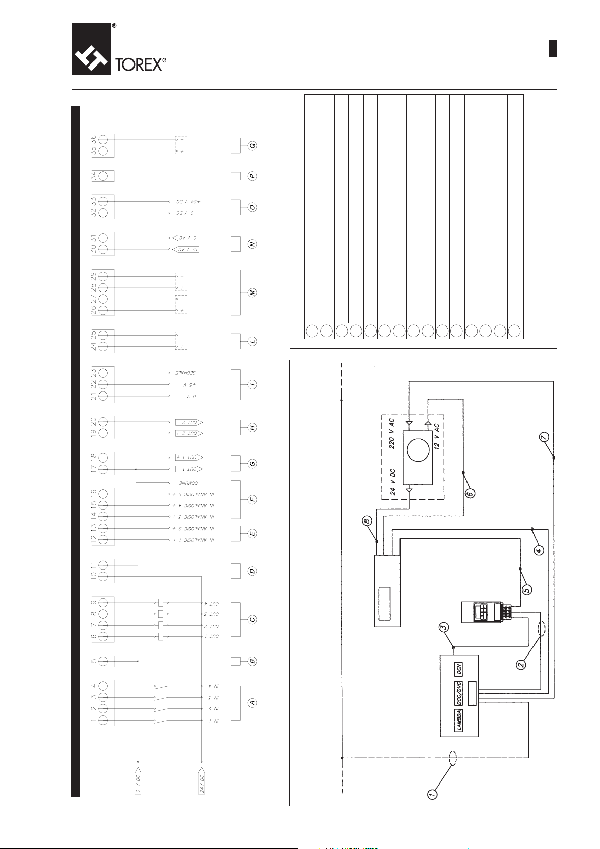
Digital inputs (push buttons) - Digitaleingänge (Tasten)
Entrées numériques (poussoirs) - Ingressi digitali (pulsanti)
Input 0V DC - Eingang 0V GS
Entrée 0V CC - Ingresso 0V CC
Digital out puts - Digitalausgänge - Sorties numériques - Uscite digitali
Input 24V DC - Eingang 24V GS
Entrée 24V CC - Ingresso 24V CC
Analogue inputs (0-10)V - Analogeingänge (0-10)V
Entrées analogiques (0-10)V - Ingressi analogici (0-10)V
E
A
D
B
C
Analogue inputs (0-5)V - Analogeingänge (0-5)V
Entrées analogiques (0-5)V - Ingressi analogici (0-5)V
Analogue outputs (0-10)V - Analogausgang (0-10)V
Sortie analogique (0-10)V - Uscita analogica (0-10)V
Analogue outputs (0-10)V - Analogausgang (0-10)V
Sortie analogique (0-10)V - Uscita analogica (0-10)V
Encoder input (only for DCN) - Eingang für Encoder (nur für DCN)
Entrée pour Codeur (uniquement pour DCN) - Ingresso x (solo x DCN)
F
I
H
G
TO.1900 M. 9
Serial contacts for another ANSY -Serielle Kontakte für weiteres ANSY
Contacts sériels pour une autre ANSY - Contatti seriali per altra ANSY
Serial contacts for ADC24 converter - Serielle Kontakte für Umrichter AGS 24
Contacts sériels pour convertisseur ACC 24 - Contatti seriali per convertitore ACC 24
Power supply 12V AC - Versorgung12V WS
Alimentation 12V CA - Alimentazione 12V CA
Power supply ENCODER 24V DC - Versorgung ENCODER 24V GS
Alimentation ENCODER 24V CC - Alimentazione ENCODER 24V CC
Not used - Unbelegt - Libre - Inutilizzato
Serial contacts for another ANSY - Serielle Kontakte für weiteres ANSY
Contacts sériels pour une autre ANSY - Contatti seriali per altra ANSY
L
M
P
Q
O
N
06.03
2
ANSY 9300 TERMINAL BOARD - KLEMMENLEISTE ANSY 9300 - BORNIER ANSY 9300 - MORSETTIERA ANSY 9300
ANSY 7350
Cable n°1 = Power supply 220 V AC
Cable n°2 = Power supply inverter
Cable n°3 = Motor
Cable n°4 = Serial line
Cable n°5 = Analog signal
Cable n°6 = 12 V AC
Cable n°7 = Power supply ansy 7350
Cable n°8 = 24 V DC
ANSY 9300
Inverter - Inverter
Inverter - Inverter
220 V AC
Other...
Power supply - Spannungsversorgung
Alimentation 220 V AC - Power supply
Page 10

ANSY 9300
-
OPERATION AND MAINTENANCE
-
BETRIEBS- UND WARTUNGSANLEITUNG
-
UTILISATION ET ENTRETIEN
-
USO E MANUTENZIONE TO.1900 M. 10
06.03
2
ANSY 7350
EXEMPLES D’APPLICATIONANWENDUNGSBEISPIELEEXAMPLES OF APPLICATION
ANSY 7335
Keyboard - Tastatur
Clavier - Tastiera
ANSY 9300
ESEMPI DI APPLICAZIONE
ANSY 9300
ANSY 7350
ANSY 7335
ANSY 9300
Keyboard - Tastatur
Clavier - Tastiera
ANSY 9300
Page 11
ANSY 9300
-
OPERATION AND MAINTENANCE
-
BETRIEBS- UND WARTUNGSANLEITUNG
-
UTILISATION ET ENTRETIEN
-
USO E MANUTENZIONE
06.03
2
TO.1900 M. 11
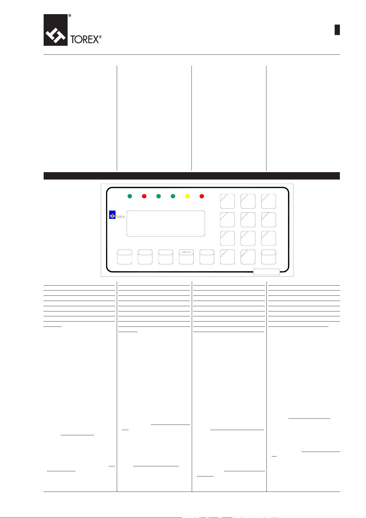
COMPONENTS
ANSY 9300 keyboard
The keyboard has the following
features:
- 17 double function keys
- 6 monitoring LED’s:
RUN: flashes when the soft-
ware is running
Stby: on when there is no ex-
ternal enabling
A/I: inactive
A/O: inactive
Numlock: on when second
function of keys is enabled
(grey part)
Alarm: inactive
BAUTEILE
Tastatur ANSY 9300
Sie besitzt folgende Merkmale:
- 17 Tasten mit Doppelfunktion
- 6 Kontrollleuchten
ÉLÉMENTS
Clavier ANSY 9300
Possède les caractéristiques
suivantes :
- 17 touches à double fonction
- 6 voyants de contrôle :
RUN: blinkt, wenn das Programm
läuft
Stdb: leuchtet, wenn die exter-
ne Freigabe fehlt
A/I: nicht aktiv
A/O: nicht aktiv
Num lock: leuchtet, wenn die
zweite Tastenfunktion aktiviert wird (grauer Teil)
Alarm: nicht aktiv
RUN : il clignote lorsque le logi-
ciel est en service
Stby: il s’allume en l’absence
d’autorisation externe
A/I : non actif
A/O: non actif
Num lock : il s’allume lorsqu’on
active la deuxième fonction
des touches (partie grise)
Alarm : non actif
Front view - Frontansicht - Vue de face - Vista frontale
ESC
MONITOR
Run
Stby A/I A/O
NEXT
MANUAL
Num Alarm
Lock
AUTOSET
7
456
GLOBAL
123
ANALOGINANALOG
.0
REFILLPARAM
89
PRINT
SILENT
OUT
COMPONENTI
Tastiera ANSY 9300
Ha le seguenti carateristiche:
- 17 tasti a doppia funzione
- 6 led di monitoraggio:
RUN: lampeggiante quando il
software è in funzione
Stby: acceso in mancanza d’abi
litazione esterna
A/I: non attivo
A/O: non attivo
Num lock: acceso quando si at-
tiva la seconda funzione dei
tasti (parte grigia)
Alarm:non attivo
TOTALLOG
+
_
ENTER
MODERESET
The description of the keys is not
given at this stage, as each standard software requires the use only
of certain keys. To avoid confusing the operator the use of the
keys and the function of the lights
will be explained later during the
detailed description of the type of
software.
CONFORMATIONS OF NUMERICAL
SET UP AND USE OF THE KEYBOARD
- The keyboard provided for the interaction of the operator with the
equipment is made up of keys with
single and double functions. When
the NumLock pilot light is on the
operator is enabled for the entry of
numbers. Some variables, however, do not permit direct entry of
numbers: a function is associated
to these that can always be activated by pressing a key, not necessarily a number key, which modifies their value.
- During numerical editing the device
accepts the numerical digits
1,2,3,4,5,6,7,8,9 and 0, which have
a double function. In the case of
functional association, for example,
the meaning of key 0 is Reset, as
will be shown later, while with numerical editing if this key is pressed
it inserts number 0 in the selected
numerical field.
Die Beschreibung der Tasten erfolgt nicht an dieser Stelle, da jede
Standard-Software nur die Verwendung einiger Tasten erfordert. Um
den Bediener nicht zu verwirren,
wird die Verwendung der Tasten
und die Funktion der Kontrollleuchten später bei der detaillierten Erklärung des Software-Typs
erläutert.
REGELN FÜR DIE NUMERISCHE
EINSTELLUNG UND VERWENDUNG DER TASTATUR
- Die für die Bedienung des Geräts
zur Verfügung stehende Tastatur
besteht aus Tasten mit Einzel- und
Doppelfunktion. Ist die Kontrollleuchte Num Lock eingeschaltet, ist
der Bediener zur Zahleneingabe befähigt. Einige Variablen lassen jedoch keine direkte numerische Eingabe zu. Ihnen ist immer eine Funktion zugeordnet, die durch Betätigung einer nicht unbedingt numerischen Taste aktivierbar ist und die
auf ihren Wert einwirkt.
- Während dem numerischen Editieren nimmt das Gerät die Zeichen 1,
2, 3, 4, 5, 6, 7, 8, 9 und 0 mit Doppelfunktion an. Im Falle einer funktionalen Zuordnung bedeutet
beispielsweise Taste 0 ein Reset,
wie wir im Folgenden zeigen werden. Die Betätigung dieser Taste
beim numerischem Editieren dient
zur Eingabe der Zahl 0 im gewählten
Zahlenfeld.
ANSY 9300
Les fonctions des touches ne sont
pas décrites durant cette phase
puisque chaque logiciel standard
ne requiert l’emploi que d’un certain nombre de touches. Pour éviter toute confusion de la part de
l’opérateur, l’emploi des touches
ainsi que la fonction des voyants
seront présentés lors de l’explication détaillée du type de logiciel.
CONVENTIONS DE CONFIGURATION NUMÉRIQUE ET EMPLOI DU
CLAVIER
- Le clavier qui permet à l’opérateur
d’interagir avec l’appareil est formé
par des touches à une ou deux fonctions. Lorsque le voyant Num Lock
est allumé, l’opérateur a la possibilité d’utiliser la saisie numérique.
Certaines variables ne permettent
cependant pas d’utiliser la saisie
numérique directe ; en revanche,
une fonction leur est associée :
celle-ci peut être activée par simple pression d’une touche, non nécessairement numérique, qui agit
sur leur valeur.
- Durant la mise en forme numérique,
l’appareillage accepte les caractères 1, 2, 3, 4, 5, 6, 7, 8, 9, et 0, qui
ont une double fonction. En cas d’association fonctionnelle, par exemple, la signification de la touche 0
est Reset, ainsi que nous aurons
l’occasion de le voir par la suite,
alors qu’avec la mise en forme numérique, sa pression introduit le
chiffre 0 dans le champ numérique.
La descrizione dei tasti non viene
effettuata in questa fase in quanto
ognuno dei software standard richiede l’utilizzo solo di alcuni tasti. Per evitare confusione all’operatore l’utilizzo dei tasti e la funzione delle spie verrà mostrata in
seguito durante la spiegazione dettagliata del tipo di software.
CONVENZIONI DI IMPOSTAZIONE
NUMERICA ED UTILIZZO DELLA
TASTIERA
- La tastiera disponibile per l’interazione dell’operatore con l’apparecchiatura è formata da tasti con singola e doppia funzione. Quando la
spia Num Lock è accesa l’operatore è abilitato all’inserimento numerico. Alcune variabili però non consentono l’inserimento numerico diretto altresì è loro associata una
funzione, attivabile sempre mediante la pressione di un tasto non necessariamente numerico, che agisce sul loro valore.
- Durante
l’editazione numerica l’ap-
parecchiatura accetta i caratteri 1,
2, 3, 4, 5, 6, 7, 8, 9, e 0 aventi
doppia funzione. Nel caso di associazione funzionale, ad esempio, il
significato del tasto 0 è Reset come
avremo modo di mostrare in seguito, mentre con
ca la sua pressione inserisce nel
campo numerico selezionato il numero 0.
l’editazione numeri-
Page 12

ANSY 9300
-
OPERATION AND MAINTENANCE
-
BETRIEBS- UND WARTUNGSANLEITUNG
-
UTILISATION ET ENTRETIEN
-
USO E MANUTENZIONE TO.1900 M. 12
06.03
2
- The same applies to the •, Enter,
Next and Esc : for these,
during numerical editing, the function indicated by the colour grey is
active.
- During both the numerical and functional editing phases, the variable
to be modified will flash. All the other keys and the functions associated to them with activated or deactivated editing will be described
as they come into use.
The following is a brief description of
the keys:
Esc
- Cancels the value just entered, and
restores the original value. This is
obviously possible only if the value has not been confirmed by pressing the key.
BackSpace
- Cancels the last number entered.
If no number has been entered it
cancels the whole numerical value
(equivalent to 0 or 0.0).
Next
This key deactivates the current
editing or focusing and activates it
on the subsequent variable. If the
value of the current variable has
been confirmed previously, its new
value is maintained, otherwise its
previous value is reset.
Enter
- Key to confirm the edited numerical value. It activates the new numerical value for the selected variable (which flashes).
• ,0,1,2,3,4,5,6,7,8,9,
- Numerical keys to enter values.
SOFTWARE
The software is memorised inside the
EPROM inserted in the TCL-R1 board.
When the device is switched on a
message will appear on the display
indicating the current type of software. The versions of Software considered “standard” by Torex are the
following:
LIW1PROP for the control of a
DB1R for the control of a
INTW1SLV for the control of con-
BTCH1ATAC for the control of a
Other possible personalizations are
available at the request of the customer.
feeding device in continuous weight loss
feeding device in
BATCH weight loss
tinuous flow belt
BATCH belt
- Das Gleiche geschieht mit den Tas-
ten •, Enter , Next und Esc,
für die beim
die grau markierte Funktion aktiv
ist.
- Die zu modifizierende Variable wird
sowohl beim numerischen als auch
funktionalen Editieren blinken.
- Alle anderen Tasten und die ihnen
durch aktiviertes und deaktiviertes
Editieren zugeordneten Funktionen
werden nach und nach bei ihrer Benutzung beschrieben.
Im Folgenden eine Kurzbeschreibung
der Tasten:
Esc
- Löscht den gerade eingegebenen
Wert und setzt den ursprünglichen
wieder zurück. Dies ist natürlich nur
möglich, wenn der Wert nicht bereits
durch Tastendruck bestätigt wurde.
Back Space
- Löscht die letzte eingegebene Zahl.
Wurde keine Zahl eingegeben, wird
der gesamte numerische Wert gelöscht (entspricht 0 oder 0.0)
Next
Deaktiviert die aktuelle Etitierung
oder Markierung, um sie auf der
nächsten Variablen zu aktivieren.
Wurde der Wert der aktuellen Variablen zuvor bestätigt, wird ihr neuer
Wert beibehalten. Anderenfalls wird
sie auf den vorhergehenden Wert
gesetzt.
Enter
- Taste zur Bestätigung des editierten Zahlenwerts. Aktiviert den neuen numerischen Wert für die gewählte Variable (die blinkt).
•, 0, 1, 2, 3, 4, 5, 6, 7, 8, 9,
- Numerische Tasten für die Eingabe
der Werte.
SOFTWARE
Die Software ist im EPROM-Speicher
der Karte TCL-R1 abgelegt.
Bei Einschaltung des Geräts zeigt das
Display den aktuellen Software-Typ
an. Als Standard-Software bietet Torex
folgende Versionen an:
LIW1PROP für die Regelung einer
DB1R für die Regelung einer
INTW1SLV für die Regelung ei-
BTCH1ATAC für die Regelung ei-
Auf Kundenanfrage sind spezifische
Versionen erstellbar.
numerischen Editieren
Dosiereinheit nach
dem Prinzip der Gewichtsabnahme im
kontinuierlichen Modus
Dosiereinheit nach
dem Prinzip der Gewichtsabnahme im
BATCH-Modus
nes Bands im kontinuierlichen Modus
nes Bands im
BATCH-Modus
- Il en est de même pour les touches
•, Enter , Next et Esc pour
lesquelles, durant
numérique, la fonction marquée par
la couleur grise est active.
- Durant la phase de mise en forme
numérique ou fonctionnelle, la fonction sur laquelle on agira se mettra
à clignoter.
- Toutes les autres touches et fonctions qui leur sont associées lorsque la mise en forme est active ou
exclue seront décrites au fur et à
mesure qu’elles seront utilisées.
Voici à présent une brève description
des touches :
Esc
- Efface la valeur qui vient d’être
programmée et rétablit l’originelle.
Bien entendu, ceci est possible si
l’on n’a pas encore validé la valeur
par une pression sur la touche.
Back Space
- Efface le dernier numéro saisi. Si
l’on n’a saisi aucun chiffre, elle efface la valeur numérique tout entière (équivalant à 0 ou 0.0).
Next
- Désactive
focalisation courante pour l’activer
sur la variable successive. Si la
valeur de la variable courante a été
préalablement confirmée, sa nouvelle valeur sera maintenue ; dans
le cas contraire, la valeur précédente sera rétablie.
Enter
- Touche de confirmation de la valeur
numérique éditée. Elle permet à la
nouvelle valeur numérique de devenir active pour la variable sélectionnée (qui clignote).
•, 0, 1, 2, 3, 4, 5, 6, 7, 8, 9
- Touches numériques pour la saisie
des valeurs.
LOGICIEL
Le logiciel est mémorisé à l’intérieur
de l’EPROM montée dans la carte
TCL-R1.
Au moment de la mise en marche de
l’instrument, une inscription s’affiche
à l’écran pour indiquer le type de logiciel utilisé. Les versions de Logiciel
que Torex considère comme étant
“standard” sont les suivantes :
LIW1PROP pour le contrôle d’un
DB1R pour le contrôle d’un
INTW1SLV pour le contrôle d’un
BTCH1ATAC pour le contrôle d’un
D’autres personnalisations peuvent
être proposées au client en fonction
d’exigences spécifiques.
la mise en forme
la mise en forme ou la
doseur en perte de
poids continu
doseur en perte de
poids en BATCH
convoyeur à bande en
continu
convoyeur à bande en
BATCH
- Altrettanto accade per i tasti •, En-
ter , , Next ed Esc per i quali,
durante l’editazione numerica, è attiva la funzione marcata dal colore
grigio.
- Durante la fase di editazione numerica o funzionale che sia, la variabile su cui si andrà ad agire lampeggia.
- Tutti gli altri tasti e le funzioni loro
associate con editazione attiva o
disabilitata verranno descritti man
mano che verranno utilizzati.
Di seguito una breve descrizione dei
tasti:
Esc
- Cancella il valore appena impostato ripristinando l’originale. Ciò è naturalmente possibile se non si è già
confermato il valore mediante la
pressione del tasto.
Back Space
- Cancella l’ultimo numero inserito.
Se non si è inserito nessun numero
cancella l’intero valore numerico
(equivalente a 0 oppure 0.0).
Next
- Disattiva l’editazione o la focalizzazione corrente per attivarla sulla successiva variabile. Se il valore della
variabile corrente è stato preventivamente confermato, il suo nuovo
valore viene mantenuto, diversamente per essa viene ripristinato il
valore precedente.
Enter
- Tasto di conferma del valore numerico editato. Rende attivo il nuovo
valore numerico per la variabile
selezionata (che lampeggia).
• , 0, 1, 2, 3, 4, 5, 6, 7, 8, 9
- Tasti numerici per l’inserimento dei
valori.
SOFTWARE
Il software è memorizzato all’interno
della EPROM inserita nella scheda
TCL-R1.
All’accensione dello strumento comparirà una scritta sul display che indicherà il tipo di software corrente. Le
versioni di Software che Torex considera “standard” sono le seguenti:
LIW1PROP per il controllo di un do-
DB1R per il contollo di un do-
INTW1SLV per il controllo di un na-
BTCH1ATAC per il controllo di un na-
É possibile ottenere altre personalizzazioni su richiesta del cliente.
satore in perdita di peso
continuo
satore in perdita di peso
in BATCH
stro in continuo
stro in BATCH
Page 13

ANSY 9300
-
OPERATION AND MAINTENANCE
-
BETRIEBS- UND WARTUNGSANLEITUNG
-
UTILISATION ET ENTRETIEN
-
USO E MANUTENZIONE
06.03
2
TO.1900 M. 13
The ANSY 9300 is basically made
up of 3 electronic boards assembled together.
ANSY 9300 besteht im wesentlichen aus 3 miteinander verbundenen elektronischen Karten:
L’ANSY 9300 se compose principalement de 3 cartes électroniques assemblées entre elles :
L’ANSY 9300 è composto principalmente da 3 schede elettroniche assemblate tra loro:
KARTE TLC-R1:
TLC-R1 BOARD:
fitted with a microprocessor, it
controls the system
TLC-EX BOARD:
controls the 4 digital inputs and
the 4 digital outputs
ANSY 7335:
interfaces all the uses in a numbered terminal board
These 3 boards combined represent the ANSY 7335 which can
be used in the feeding systems
with 3 or more components in
communication with other boards.
Monitoring is possible by using a
membrane keyboard connected
to the TLC-R1.
Other components are used for
the operation of the ANSY inside
the system to be controlled and
are described in the following
pages.
WARNING!!:
THE ASSEMBLY OF THESE
COMPONENTS MUST BE CARRIED OUT WITH CARE
ANSY 9300 KEYPAD
On the back of the keypad two
boards can be seen. These boards
contain:
The connectors (16 poles for connection to the TLC-R1 board: the
P9 connector placed vertically on
the left and the P12 connector
placed horizontally below (see
diagram).
Power is 5VDC supplied by a connection cable of the P12 connectors.
ausgestattet mit Mikroprozessor, dient zur Systemsteuerung
KARTE TLC-EX:
steuert die 4 Digitalein- und –
ausgänge
KARTE ANSY 7335:
koppelt alle Verbraucher in einer nummerierten Klemmenleiste
Aus der Kombination dieser 3
Karten entsteht der Regler ANSY
7335, der in den Dosiersystemen
mit 3 oder mehr Komponenten in
Verbindung mit weiteren Karten
eingesetzt werden kann. Die Überwachung erfolgt mit Hilfe einer
an der Karte TLC-R1 angeschlossenen Membrantastatur.
Auf den nächsten Seiten werden
die anderen für den Betrieb von
ANSY innerhalb des zu kontrollierenden Systems erforderlichen
Elemente beschrieben.
ACHTUNG!
DIE MONTAGE DIESER ELEMENTE MUSS MIT SORGFALT
DURCHGEFÜHRT WERDEN.
TASTATUR ANSY 9300
Auf der Rückseite der Tastatur sind
zwei Karten sichtbar, auf denen
sich die Steckverbinder (16-polig)
für den Anschluss an die Karte
TLC-R1 befinden: der Steckverbinder P9, in senkrechter Stellung
links und der Steckverbinder P12,
in waagrechter Stellung unten
(siehe Zeichnung).
Die Versorgungsspannung beträgt 5 V GS und wird über das
Verbindungskabel von Steckverbinder P12 zugeführt.
CARTE TLC-R1 :
équipée d’un microprocesseur,
elle gère le système
CARTE TLC-EX :
elle gère les 4 entrées et les 4
sorties numériques
CARTE ANSY 7335 :
elle interface tous les utilisateurs dans un bornier numéroté
L’union de ces 3 cartes représente l’ANSY 7335 qui peut être utilisée dans les systèmes à 3 éléments ou plus étant en communication avec d’autres cartes.
Le contrôle s’effectue à travers un
clavier à membrane connecté à
la TLC-R1.
D’autres éléments sont utilisés
pour faire fonctionner l’ANSY
dans le système devant être contrôlé ; ils sont décrits dans les pages successives.
ATTENTION !!
L’ASSEMBLAGE DE CES ÉLÉMENTS DOIT ÊTRE EFFECTUÉ
AVEC SOIN
CLAVIER ANSY 9300
Deux cartes sont visibles dans la
partie arrière du clavier. Ces cartes contiennent les Connecteurs
(à 16 pôles) qui permettent d’effectuer la connexion avec la carte TLC-R1 : le connecteur P9 situé à gauche et en position verticale, et le connecteur P12 situé
en bas et en position horizontale
(voir le dessin).
L’alimentation est de 5 V DC et
est fournie par un câble de raccordement des connecteurs P12.
SCHEDA TLC-R1:
dotata di microprocessore, gestisce il sistema
SCHEDA TLC-EX:
gestisce i 4 ingressi e le 4 uscite
digitali
SCHEDA ANSY 7335:
interfaccia tutte le utenze in una
morsettiera numerata
L’unione di queste 3 schede rappresenta l’ANSY 7335 che può
essere utilizzata nei sistemi di
dosaggio a 3 o più componenti
in comunicazione ad altre schede.
Il monitoraggio è consentito per
mezzo di una tastiera a membrana collegata alla TLC-R1.
Altri componenti vengono usati
per il funzionamento dell’ANSY
all’interno del sistema da controllare e sono descritti nelle pagine
seguenti.
ATTENZIONE !!:
L’ASSEMBLAGGIO DI QUESTI
COMPONENTI VA ESEGUITO
CON CURA
TASTIERA ANSY 9300
Sul retro della tastiera sono visibili due schede. In queste schede sono presenti i
Connettori ( a 16 poli) per la connessione con la scheda TLC-R1:
il connettore P9 posto a sinistra
in verticale ed il connettore P12
posto in basso orizzontalmente
(vedere disegno).
L’alimentazione è di 5 V DC fornita tramite cavo di collegamento dei connettori P12.
ANSY 9300 Keypad board - Karte Tastatur ANSY 9300 - Carte clavier ANSY 9300 - Scheda tastiera ANSY 9300
Rear view - Rückansicht - Vue arriére - Vista posteriore
Page 14

ANSY 9300
-
OPERATION AND MAINTENANCE
-
BETRIEBS- UND WARTUNGSANLEITUNG
-
UTILISATION ET ENTRETIEN
-
USO E MANUTENZIONE TO.1900 M. 14
06.03
2
TLC-R1
This board contains:
- the EPROM:
in which is memorised the software
program that determines the type
of operation of the equipment.
- PS3 and PS4 JUMPERS and the P1
and P4 connectors, by means of
which it is possible to set the type
of communication with the external
components (PC, PLC, other ANSY’s etc.) and connect them to the
board.
- TR1 TRIMMER
with which it is possible to regulate
the contrast of the keyboard.
- BT1 BUFFER BATTERY
which makes it possible to maintain
data in the memory.
- P2, P7 and P8 CONNECTORS
which permit connection to the TLCEX board.
- P3 and P6 CONNECTORS
which permit connection to the
ANSY 7335 board.
- P9 and P12 CONNECTORS
(20 poles) which permit connection
with keyboard/screen.
TLC-R1
In dieser Karte befinden sich:
- der EPROM-Speicher,
in dem das Programm für die Funk-
tionsweise des Geräts abgelegt ist
-die SCHALTBRÜCKEN PS3 und
PS4 sowie die Wannenstecker P1
und P4.
Sie ermöglichen die Einstellung der
Kommunikationsart mit den externen Elementen (PC, SPS, weitere
ANSY, usw.) und deren Anschluss
an die Karte
- der Trimmer TR1
zur Einstellung des Kontrasts der
Tastatur
-die PUFFERBATTERIE BT1
zur Speicherung der Daten
- die STECKVERBINDER P2, P7 und
P8 für den Anschluss an die Karten
TLC-EX
-die STECKVERBINDER P3 und P6
für den Anschluss an die Karte
ANSY 7335
-die Steckverbinder P9 und P12 (20-
polig) für den Anschluss an die
Bildschirmtastatur
TLC-R1
Dans cette carte se trouvent :
- l’EPROM,
dans laquelle est mémorisé le programme logiciel qui détermine le
type de fonctionnement de l’appareillage.
- les CAVALIERS PS3 et PS4 et les
connecteurs P1 et P4,
à travers lesquels il est possible
d’établir le type de communication
avec des éléments externes (PC,
PLC, d’autres ANSY, etc.) et de les
connecter à la carte.
- le TRIMMER TR1,
avec lequel il est possible de régler
le contraste du clavier.
- la BATTERIE TAMPON BT1,
qui permet de conserver les données en mémoire.
- les CONNECTEURS P2, P7 et P8,
qui permettent d’effectuer la connexion avec la carte TLC-EX.
- les CONNECTEURS P3 et P6,
qui permettent d’effectuer la connexion avec la carte ANSY 7335.
- les CONNECTEURS P9 et P12,
(à 20 pôles) qui permettent d’effectuer la connexion avec le clavier /
écran.
TLC-R1
In questa scheda si trovano:
la EPROM :
nella quale e’ memorizzato il programma software che determina il
tipo di funzionamento dell’apparecchiatura.
-
i JUMPER PS3 e PS4 e i connettori
a vaschetta P1 e P4,
attraverso i quali e’ possibile settare il tipo di comunicazione con componenti esterni (P.C. ,PLC,,altre
ANSY ecc...) e connetterli alla scheda.
-
il TRIMMER TR1,
con il quale e’ possibile regolare il
contrasto della tastiera.
-
la BATTERIA TAMPONE BT1, che
permette di mantenere in memoria i
dati .
-
i CONNETTORI P2,P7e P8,
che permettono la connessione con
la scheda TLC-EX.
-
I CONNETTORI P3 e P6,
che permettono la connessione con
la scheda ANSY 7335.
-
I CONNETTORI P9 e P12,
(a 20 poli) che permettono la connessione con la tastiera/schermo.
The power supply voltage is of 12V
AC.
Die Versorgungsspannung hat einen
Wert von 12V WS.
TLC-R1
Le courant d’alimentation est de 12 V
CA.
La tensione di alimentazione è di 12V
CA.
Page 15

ANSY 9300
-
OPERATION AND MAINTENANCE
-
BETRIEBS- UND WARTUNGSANLEITUNG
-
UTILISATION ET ENTRETIEN
-
USO E MANUTENZIONE
06.03
2
TO.1900 M. 15
TLC-EX
The following are contained in
this board:
- LED’s 1,2,3,4,5,6,7 and 8
which indicate the status of the
digital inputs and outputs according to the following criteria:
1) digital input 1(led on with con-
tact closed)
2) digital input 2(led on with con-
tact closed)
3) digital input 3(led on with con-
tact closed)
4) digital input 4(led on with con-
tact closed)
5) digital output 1(led on with
high output)
6) digital output 2(led on with
high output)
7) digital output 3(led on with
high output)
8) digital output 4(led on with
high output)
- P4,P5 and P6 CONNECTORS
which permit connection with
the ANSY 7335 board
- P1,P2 and P3 CONNECTORS
which permit connection with
the ELX-R1 board
TLC-EX
Diese Karte ist bestückt mit:
- den LED’s 1, 2, 3, 4, 5, 6, 7, und
8, die den Zustand der Digitalein- und –ausgänge nach folgendem Kriterium angeben:
1) Digitaleingang 1 (Led er-
leuchtet bei Öffnerkontakt)
2) Digitaleingang 2 (Led er-
leuchtet bei Öffnerkontakt)
3) Digitaleingang 3 (Led er-
leuchtet bei Öffnerkontakt)
4) Digitaleingang 4 (Led er-
leuchtet bei Öffnerkontakt)
5) Digitalausgang 1 (Led er-
leuchtet bei hohem Ausgang)
6) Digitalausgang 2 (Led er-
leuchtet bei hohem Ausgang)
7) Digitalausgang 3 (Led er-
leuchtet bei hohem Ausgang)
8) Digitalausgang 4 (Led er-
leuchtet bei hohem Ausgang)
- den STECKVERBINDERN P4,
P5 und P6 für den Anschluss
an die Karte ANSY 7335
- den STECKVERBINDERN P1,
P2 und P3 für den Anschluss
an die Karte ELX-R1.
TLC-EX
TLC-EX
Dans cette carte se trouvent :
- les VOYANTS 1, 2, 3, 4, 5, 6, 7,
et 8 qui indiquent l’état des entrées et des sorties numériques
sur la base du critère suivant :
1) entrée numérique 1 (voyant
allumé avec contact fermé)
2) entrée numérique 2 (voyant
allumé avec contact fermé)
3) entrée numérique 3 (voyant
allumé avec contact fermé)
4) entrée numérique 4 (voyant
allumé avec contact fermé)
5) sortie numérique 1 (voyant
allumé avec sortie haute)
6) sortie numérique 2 (voyant
allumé avec sortie haute)
7) sortie numérique 3 (voyant
allumé avec sortie haute)
8) sortie numérique 4 (voyant
allumé avec sortie haute)
- les CONNECTEURS P4, P5 et
P6,
qui permettent d’effectuer la
connexion avec la carte ANSY
7335.
- les CONNECTEURS P1, P2 et
P3,
qui permettent d’effectuer la
connexion avec la carte ELXR1.
TLC-EX
In questa scheda sono alloggiati:
- i LED 1,2,3,4,5,6,7 e 8 che indicano lo stato degli ingressi e
delle uscite digitali secondo il
seguente criterio:
1) ingresso digitale 1 (led acce-
so con contatto chiuso)
2) ingresso digitale 2 (led acce-
so con contatto chiuso)
3) ingresso digitale 3 (led acce-
so con contatto chiuso)
4) ingresso digitale 4 (led acce-
so con contatto chiuso)
5) uscita digitale 1 (led acceso
con uscita alta)
6) uscita digitale 2 (led acceso
con uscita alta)
7) uscita digitale 3 (led acceso
con uscita alta)
8) uscita digitale 4 (led acceso
con uscita alta)
- I CONNETTORI P4,P5 e P6,
che permettono la connessione con la scheda ANSY 7335
- I CONNETTORI P1,P2, e P3,
che permettono la connessione alla scheda ELX-R1.
Page 16

ANSY 9300
-
OPERATION AND MAINTENANCE
-
BETRIEBS- UND WARTUNGSANLEITUNG
-
UTILISATION ET ENTRETIEN
-
USO E MANUTENZIONE TO.1900 M. 16
06.03
2
ANSY 7335 INTERFACE
This board contains:
- J1,J2 and J3 JUMPERS
by means of which it is possible to set the type of supply of
the encoder.
- A TERMINAL BOARD NUM-
BERED FROM 1 TO 36
to which all users can be connected.
- P1 AND P6B CONNECTORS
for connection to the TLC-R1
board.
- P4,P5 AND P6 CONNECTORS
for connection to the TLC-EX
board.
- JP3 Terminal Board
permits connection to the ANSY
9400 keypad if present. By
means of this terminal board the
keypad is supplied with 12V
AC.
SCHNITTSTELLE ANSY 7335
Diese Karte ist bestückt mit:
- den SCHALTBRÜCKEN J1, J2
und J3,
über die die Versorgungsart
des Encoders eingestellt werden kann
- einer VON 1 BIS 36 NUMMERIERTEN KLEMMENLEISTE,
an der sämtliche Verbraucher
angeschlossen werden können
- den STECKVERBINDERN P1
UND P6B
für den Anschluss an die Karte TLC-R1
- den STECKVERBINDERN P4,
P5 UND P6
für den Anschluss an die Karte TLC-EX
- der KLEMMENLEISTE JP3
für den Anschluss an eine
eventuelle Tastatur ANSY 9400.
Über diese Klemmenleiste wird
die Tastatur mit 12V WS gespeist
INTERFACE ANSY 7335
Dans cette carte se trouvent :
- les CAVALIERS J1, J2 et J3,
à travers lesquels il est possible d’établir le type d’alimentation du codeur.
- un BORNIER NUMÉROTÉ DE 1
À 36,
auquel il est possible de connecter tous les utilisateurs.
- les CONNECTEURS P1 et P6B,
qui permettent d’effectuer la
connexion avec la carte TLCR1.
- les CONNECTEURS P4, P5 et
P6,
qui permettent d’effectuer la
connexion avec la carte TLCEX.
- Bornier JP3,
qui permet d’effectuer le raccordement à un éventuel clavier ANSY 9400. Ce bornier
fournit une alimentation de 12
V CA au clavier.
INTERFACCIA ANSY 7335
In questa scheda sono alloggiati:
- I JUMPER J1,J2e J3,
attraverso i quali e’ possibile
settare il tipo d’alimentazione
dell’encoder.
- Una MORSETTIERA NUMERA-
TA DA 1 A 36,
alla quale e’ possibile collegare tutte le utenze.
-ICONNETTORI P1 E P6B,
per al connessione con la
scheda TLC-R1.
-I CONNETTORI P4,P5 E P6,
per la connessione con la
scheda TLC-EX.
- Morsettiera JP3,
permette il collegamento ad
un’eventuale tastiera ANSY
9400. Attraverso questa morsettiera si alimenta la tastiera
con 12 V CA.
The power supply of the board
is of 24V AC.
Die Versorgungsspannung dieser Karte beträgt 24V WS.
ANSY 7335
Cette carte est alimentée à 24 V
CA.
L’alimentazione di questa scheda è di 24 V CA.
36
18
19
1
Page 17

ANSY 9300
-
OPERATION AND MAINTENANCE
-
BETRIEBS- UND WARTUNGSANLEITUNG
-
UTILISATION ET ENTRETIEN
-
USO E MANUTENZIONE
COMPONENTS
ELEMENTE
ÉLÉMENTS
COMPONENTI
06.03
2
TO.1900 M. 17
ANSY 7350 POWER SUPPLY
This is used to transform the 230
V AC voltage into the voltage
used by the ANSY and by its other components, 12V AC, 12VDC
and 24VDC.
Fusibile - Fusibile
Fusibile - Fusibile
250V-3.15A
OUTPUT
12 V AC
L
N
NETZTEIL ANSY 7350
Dient zur Umwandlung von 230V
WS in die für das ANSY Gerät
und die anderen Elemente des
Systems verwendeten Spannungswerte, d.h. 12V WS, 12V
GS und 24V GS.
ALIMENTATEUR ANSY 7350
Il sert à transformer le courant
de 230 V CA dans celui utilisé
par l’ANSY et par ses autres
composants, qui est de 12 V CA,
12 V CC et 24 V CC.
ALIMENTATORE ANSY 7350
Serve per trasformare la tensione di 230V CA nella tensione utilizzata dall’ANSY, e dagli altri suoi
componenti, che è di 12V CA ,
12V CC e 24V CC.
OUTPUT+12V
0V
12 V DC
250V - 3.15A
INPUT
230 V AC
L
N
Fuse - Sicherung
Fusible - Fusibile
250V-1A
As can be seen in the diagram
there are four terminals on the
device.
- On the top right is the terminal
used for the power supply to
the boards (TLC, ANSY 7335).
- On the bottom left is the terminal used to supply power to
the ANSY 7350 at 230V AC.
- On the top right is a terminal
which is not used for our applications.
- On the bottom right is the terminal for the supply of power
to the buttons and/or selectors
and relays.
Aus der Zeichnung geht hervor,
dass das Gerät über vier Klemmen verfügt:
- Oben links befindet sich die
Klemme zur Versorgung der
Karten (TLC, ANSY 7335)
- Unten links befindet sich die
Klemme zur Versorgung von
ANSY 7350 mit 230V WS.
- Die Klemme oben rechts wird
für unsere Applikationen nicht
verwendet.
- Unten rechts befindet sich die
Klemme zur Versorgung der
Tasten und/oder Wahlschalter
und Relais.
Ainsi que le montre le dessin, les
bornes présentes sur l’instrument sont au nombre de 4.
- En haut à gauche se trouve la
borne qui permet d’alimenter
les cartes (TLC, ANSY 7335)
- En bas à gauche se trouve la
borne qui permet d’alimenter
l’ANSY 7350 à 230 V CA.
- En haut à droite se trouve une
borne qui n’est pas utilisée
pour nos applications.
- En bas à droite se trouve la
borne qui permet d’alimenter
les poussoirs et/ou les sélecteurs et les relais.
+24V
0V
OUTPUT
24V DC
Come si vede dal disegno sono
quattro i morsetti presenti sullo
strumento.
- In alto a sinistra è presente il
morsetto che consente di alimentare le schede (TLC, ANSY
7335).
- In basso a sinistra c’è il morsetto che consente l’alimentazione dell’ANSY 7350 a 230 V
CA .
- In alto a destra è presente un
morsetto che non viene utilizzato per le nostre applicazioni.
- In basso a destra si trova infine il morsetto che consente di
alimentare i pulsanti e/o selettori e relè.
Page 18

ANSY 9300
-
OPERATION AND MAINTENANCE
-
BETRIEBS- UND WARTUNGSANLEITUNG
-
UTILISATION ET ENTRETIEN
-
USO E MANUTENZIONE TO.1900 M. 18
COMPONENTS
ELEMENTE
ÉLÉMENTS
COMPONENTI
06.03
2
ADC-24 CONVERTER
- This is used to convert the analogue signal coming from the
load cell into a digital signal
which can be used by the
ANSY. One is required for the
control of each single load cell.
- The power supply is 230VAC.
- Inside the converter are a series of “strips” for jumpers,
with which it is possible to identify the type of ADC to be controlled.
Example:
- if the ANSY has to control two
ADC’s (therefore 2 weighing
systems) the first is recognised
because it has no jumper, while
the second will have a jumper.
-eludoM ludoM
-eludoM oludoM
42CDA
WANDLER ADC-24
- Dient zur Umwandlung des von
der Ladezelle kommenden
Analogsignals in ein vom ANSY
verwertbares Digitalsignal.
Jede einzelne Ladezelle benötigt einen Wandler.
- Die Versorgungsspannung beträgt 230V WS.
- Im Inneren des Wandlers befinden sich eine Reihe von
„Strips” für Schaltbrücken, mit
denen der zu regelnde ADCTyp gekennzeichnet werden
kann.
Beispiel:
- Wenn ANSY zwei ADC-Module steuern muss (also zwei Wägesysteme), wird das erste
daran erkannt, dass es keine
Schaltbrücke hat, während das
zweite eine besitzt.
ANALOG CONVERTER ADC 24
-stib61,ressecorporcimhtiwdraoB rossezorporkiM-tiB-61timetraK
-stib61àruessecorporcimcevaetraC stib61aerossecorporcimnocadehcS
-stib12,noisrevnoclatigid/eugolanafoegatS tiB12iebmuidatssgnuldnawmU-D/A
-sllecdaolotnoitcennocrofrotcennocelop6 ellezedaLnassulhcsnArüfrednibrevkcetSregilop-6
CONVERTER ADC-24
- Il est utilisé pour convertir le signal analogique provenant de
la cellule de chargement en un
signal numérique pouvant être
utilisé par l’ANSY. Il en faut un
pour le contrôle de chaque
capteur de chargement.
- L’alimentation est de 230 V CA.
- À l’intérieur du convertisseur
se trouve une série de “strip”
pour cavaliers, avec lesquels
il est possible d’identifier le type
d’ADC devant être contrôlé.
Exemple :
si l’ANSY doit gérer deux ADC
(donc, 2 systèmes de pesage),
le premier est reconnu car il n’a
pas de cavalier alors que le second, lui, en a un.
-)HXDXL(mm05x09x061muinimuladedurtxenireniatnoC )HxTxL(mm05x09x061,muinimulAmetsserpeggnartssuaesuäheG
-)HXPXL(mm05x09x061édurtxemuinimulanereitîoB )HXPXL(05x09x061mmosurtseoinimullanierotinetnoC
-stib12àeuqirémun/euqigolananoisrevnocedegatÉ stib12aelatigid/ocigolanaenoisrevnocidoidatS
-tnemegrahcedruetpacnuàtnemedroccarelruopselôp6àruetcennoC ociracidallecaotnemagellocrepilop6aerottennoC
CONVERTER ADC-24
- E’ utilizzato per convertire il segnale analogico proveniente
della cella di carico in segnale
digitale utilizzabile dall’ ANSY.
Ne serve uno per il controllo di
ogni singola cella di carico.
- L’alimentazione è di 230 V AC.
- All’interno del convertitore è
presente una serie di “strip”
per jumpers, con cui è possibile identificare il tipo di ADC da
controllare.
Esempio :
se l’ANSY deve gestire due
ADC (quindi 2 sistemi di pesatura) il primo viene riconosciuto perché non ha il jumper,
mentre il secondo avrà il jumper.
.tinugnideefehtnodellatsniebot,sllecdaolehtmorfthgiewehtgniriuqcarof,eludomerawdraH
treillatsnistagerggareisoDseddroBnadriw,nellezedaLsuasthciweGsedgnussafrEruzludoM-erawdraH
.egasodedepuorguddrobàrellatsnià,tnemegrahcedsruetpacedritrapàsdiopudnoitisiuqca'lruopeludoM
oiggasodidoppurgledodrobaerallatsniad,ociracidellecadosepledenoizisiuqcarep,erawdraHoludoM
DUABK6.351noissimsnartfoycneuqerf.xam;rotcennocelop9htiw584-SRnoitacinummoclairesfoecafretnI
DUABK6,351zneuqerfsgnugartrebÜxam,rekcetsnennaWmegilop-9tim584-SRelletsttinhcSelleireS
DUABK6.351:noissimsnarted.xamecneuqérf;selôp9àruetcennocceva584-SReirésnoitacinummocedecafretnI
DUABK6.351enoissimsartid.xamazneuqerf;ilop9aattehcsavaerottennocnoc584-SRelairesenoizacinumocidaiccafretnI
Page 19

ANSY 9300
-
OPERATION AND MAINTENANCE
-
BETRIEBS- UND WARTUNGSANLEITUNG
-
UTILISATION ET ENTRETIEN
-
USO E MANUTENZIONE
06.03
2
TO.1900 M. 19
SIEMENS INVERTER (if
different please see
attached manual)
- This is used to regulate the
number of revolutions of the
electric motor after receiving
information from the ANSY
9300.
- It is not used for the software
that controls the belt in BATCH.
- The power supply of this board
is 230VAC.
The wiring diagram is as follows:
Inverter face - Frontblende
Façade inverseur - Facciata inverter
•
SIEMES INVERTER (im Falle eines anderen Modells, siehe
das beiliegende Handbuch)
- Dient zur Regelung der Drehzahl des Elektromotors anhand
der von ANSY 9300 erhaltenen
Informationen.
- Wird nicht für die Software
benutzt, die das Band im
BATCH-Modus steuert
- Diese Karte wird mit 230V WS
versorgt.
Nachstehend das Anschlussschema:
View from below - Ansicht von unten
Vue par le bas - Vista dal basso
1
2
INVERSEUR SIEMENS (en cas
de produit différent, voir le
manuel en annexe)
- Il est utilisé pour régler le nombre de tours du moteur électrique suite aux informations
transmises par l’ANSY 9300.
- Il n’est pas employé pour le logiciel qui contrôle le convoyeur
à bande en BATCH.
- Cette carte est alimentée à 230
V AC.
Le schéma des câblages est le
suivant :
Intern al term inal bo ars - Interne Klemmenleiste
5
6
INVERTER SIEMENS(nel caso
sia diverso vedere manuale
allegato)
- E’ utilizzato per regolare il numero di giri del motore elettrico
in seguito alle informazioni ricevute dall’ANSY 9300.
- Non viene utilizzato per il software che controlla il nastro in
BATCH.
- L’alimentazione di questa scheda è di 230 V AC.
Lo schema per i cablaggi è il seguente:
Bo rnier i nterne - Morsettiera interna
•
10
3
•
•
1
8
9
2
3
4
5
6
7
8
9
01
syalpsid
stcatnoc
yalpsid
elbavomerhtiwdapyeK
rofrevocnoitcetorP
selbacehtrofhtraE
retrevniehtmorfgnivirra
retrevnifohtraeniaMsretrevnIsedgnudretpuaH
htiwdapyekrofrotcennoC
slanimretyrailixuA
)51ot1morf(
slanimretrewoPnemmelksgnutsieLecnassiupàsenroBaznetopaittesroM
:STUPNIEUGOLANA
slanimretmorfevirraeseht
ehtfo02-91ro81-71
ehtnognidneped(YSNA
)erawtfosfoepyt
:tcatnocTRATS
ehtrofdesolcebtsumsiht
krowotecived
:YALERMRALA
.mralanoitareporetrevni
.dehsiwsadesueboT
timrutatsaT
etkatnoK
yalpsiDtim
nemmelksfliH
)51sib1nov(
4
7
•
syalpsiDnerabheizsuareh
redztuhcSmuzettalpkceD
retrevnImoveidrüfgnudrE
lebaKnednemmok
rutatsaTrüfrednibrevkcetS
:EGNÄGNIEGOLANA
nemmelKnednovnemmok
sed02-91redo81-71
gignähba(srelgeR-YSNA
)pyT-erawtfoSmov
ssum,tkatnoK-TRATS
timad,niesnessolhcseg
treinoitknuftäreGsad
mralA:YALERMRALLA
hcannnak,beirteB-retrevnI
.nedrewtztunebnebeileB
selbitcartxe
ruesrevni'l
ruehciffa
)51à1ed(
)leicigol
ruehciffacevareivalC
noitcetorpedelcrevuoC
stcatnocsed
selruoperretalàesiM
edecnanevorpneselbâc
elapicnirperretalàesiM
ruesrevni'led
àreivalcruopruetcennoC
seriailixuasenroB
SEUQIGOLANASEÉRTNE
senrobsedtnevirraselle:
YSNA'led02-91uo81-71
edepytuddnepédalec(
tiodli:TRATSedtcatnoC
eriafruopémrefertê
tnemurtsni'lrennoitcnof
edemrala:YALERMRALA
edtnemennoitcnof
ésilituertêtueP.ruesrevni'l
erisédelnoemmoc
ilibiartse
ittatnoc
yalpsid
otnemurts
yalpsidnocareitsaT
enoizetorprepoihcrepoC
ehcivacireparreT
retrevni'lladonavirra
elapicnirparreT
retrevni'lled
aareitsatreperottennoC
irailisuaittesroM
)51a1ad(
:ICIGOLANAISSERGNI
-71ittesromiadonavirra
lled02-91eruppo81
opitladednepid(YSNA
)erawtfosid
:TRATSidottatnoC
reposuihceresseeved
oleranoiznufraf
:YALERMRALLA
otnemanoiznufidemralla
erasuaD.retrevni'lled
elouvisemoc
Page 20

ANSY 9300
-
OPERATION AND MAINTENANCE
-
BETRIEBS- UND WARTUNGSANLEITUNG
-
UTILISATION ET ENTRETIEN
-
USO E MANUTENZIONE TO.1900 M. 20
COMPONENTS
ELEMENTE
ÉLÉMENTS
COMPONENTI
06.03
2
NC3N CONTROLLER
- This is used to vary the speed
of vibration of the vibrating
conveyor (DVG) by means of
an analogue signal coming from
the ANSY 9300.
- One is required for the control
of each single feeding unit.
The power supply of the controller is 230 VAC.
CONTROLLER NC3N
- Wird zur Regelung der Rüttelgeschwindigkeit des Rüttelkanals (DVG) mit Hilfe eines von
ANSY 9300 kommenden Analogsignals benutzt.
- Jede einzelne Dosiereinheit
benötigt einen Controller.
Die Versorgungsspannung des
Controllers beträgt 230V WS
4
3
2
1
0
CONTROLLER NC3N
- Il est utilisé pour modifier la vitesse de vibration de la goulotte vibrante (DVG) au moyen
d’un signal analogique provenant de l’ANSY 9300.
- Il en faut un pour le contrôle de
chaque unité de dosage.
Le contrôleur est alimenté à 230
V CA.
5
6
7
8
9
1
0
CONTROLLER NC3N
- E’ utilizzato per variare la velocità di vibrazione della canala
vibrante (DVG) per mezzo di
un segnale analogico proveniente dall’ ANSY 9300..
- Ne serve uno per il controllo di
ogni singola unità di dosaggio.
L’alimentazione del controller è
di 230V CA.
CONTROLLER-NC3N-Connexion- Anschlüsse - Connexions - Connessioni
FROM ANSY9300
*PIN 20 o 17
*PIN 19 o 18
* Depending on the couple of con-
tacts intended for use: 17-18 or 19-
20.
* Hängt vom zu benutzenden Paar
Kontakte ab: 17-18 oder 19-20
* Dépend de la paire de contacts que
l’on souhaite utiliser : 17-18 ou 19-20
* Dipende dalla coppia di contatti che
intendo utilizzare: 17-18 o 19-20
230 V AC
A
B
B1
CD+
F
G
ILMNOPTUVZ
Earth - Erde - Terre - Terra
To the vibrator connector
Zum Steckverbinder des Rüttlers
Vers le connecteur du vibreur
Al connettore del vibratore
Page 21

ANSY 9300
-
OPERATION AND MAINTENANCE
-
BETRIEBS- UND WARTUNGSANLEITUNG
-
UTILISATION ET ENTRETIEN
-
USO E MANUTENZIONE
06.03
2
TO.1900 M. 21
CONNECTOR BLOCK
Below is a diagram showing the
connections possible to our connector block which is used for
the connection of the power
supply cables of the ADC 24 and
the serial communication. If an
ENCODER is present it is used
also for the connection of its
cables.
KLEMMENKASTEN
Das nachstehende Schema veranschaulicht die möglichen Anschlüsse an den Klemmenkasten, der zur Verbindung der Versorgungskabel des ADC 24 und
seriellen Datenübertragung
dient. Bei Verwendung eines
ENCODERS dient der Klemmenkasten auch für den Anschluss
dessen Kabel.
BOÎTIER DE DÉRIVATION
Nous présentons ci-après un
schéma mettant en évidence les
connexions pouvant être effectuées à notre boîtier de dérivation qui sert à la jonction des
câbles d’alimentation de l’ADC 24
et à la communication série. Si le
CODEUR est utilisé, il est également utilisé pour effectuer le branchement de ses câbles.
SCATOLA DI DERIVAZIONE
Qui di seguito è presente uno
schema che evidenzia le connessioni possibili alla nostra scatola di derivazione, che serve per
la giunzione dei cavi di alimentazione dell’ ADC 24 e la comunicazione seriale. Nel caso che ci
sia l’ENCODER è usato anche per
la giunzione dei suoi cavi..
STANDARD EQUIPMENT
The standard equipment provides:
- TLC-R1 board
- TLC-EX board
- ANSY 7335 board
- Inverter (excluding the DCN in
BATCH) or NC3N Controller
(only for DGV)
- ADC-24 converter
- Connector block.
* Terminals for the encoder used only on DCN
* Nur auf DCN verwendete Klemmen für Encoder
* Bornes pour le codeur utilisés uniquement sur DCN
* Morsetti per l’encoder utilizzati solo su DCN
STANDARDAUSRÜSTUNG
Die Standardausrüstung umfasst:
- Karte TLC-R1
- Karte TLC-EX
- Karte ANSY 7335
- Inverter (außer DCN in BATCH)
oder Controller NC3N (nur für
DGV)
- Wandler ADC-24
- Klemmenkasten
ÉQUIPEMENT STANDARD
L’équipement standard prévoit :
- une carte TLC-R1
- une carte TLC-EX
- une carte ANSY 7335
- un inverseur (hormis le DCN en
BATCH) ou bien un Contrôleur
NC3N (uniquement pour DGV)
- un convertisseur ADC-24
- un boîtier de dérivation.
DOTAZIONE STANDARD
La dotazione standard prevede:
- scheda TLC-R1
- scheda TLC-EX
- scheda ANSY 7335
- Inverter (escluso il DCN in BATCH) oppure Controller NC3N
(solo per DGV)
- Convertitore ADC-24
- Scatola di derivazione.
Page 22

ANSY 9300
-
OPERATION AND MAINTENANCE
-
BETRIEBS- UND WARTUNGSANLEITUNG
-
UTILISATION ET ENTRETIEN
-
USO E MANUTENZIONE TO.1900 M. 22
06.03
2
INSTALLATION
The ANSY 9300 is normally delivered already assembled, but
if it should be necessary to open
the device and make some modifications to the boards (for example the substitution of the
Eprom, etc.) the procedure is
described herein.
Also included in the following
pages is the procedure for the
installation of the other (external) components that are required for the operation of the
device.
The following dismantling procedure is to be followed only if the
internal boards are to be worked
on. As far as the actual installation is concerned go ahead to
the next paragraph.
- If operating on a device that is
already working: DISCON-
NECT ALL THE ELECTRIC
POWER SUPPLIES before
starting to dismantle;
- Remove the keypad delicately
by using a screwdriver as a
lever in the appropriate notches on the front frame of the
device (see drawing).
- Then disconnect the tape cables that connect the board of
the keypad to the TLC-R1 board
by means of the P9 and P12
connectors.
Aluminium box - Aluminium gehäuse
Bôte en aluminium - Scatola in alluminio
EINBAU
Normalerweise wird ANSY 9300
bereits montiert zum Versand
gegeben. Sollte eine Öffnung des
Geräts für einen Eingriff an den
Karten (z.B. Auswechseln des
Eprom, usw.) erforderlich sein,
ist die nachstehend beschriebene Vorgehensweise einzuhalten.
Auf den nächsten Seiten ist
auch der Einbau der anderen Elemente (externe) erläutert, die für
den Betrieb des Regelgeräts notwendig sind.
Die nachstehend beschriebenen
Arbeitsgänge sind nur für den
Fall eines Eingriffs an den Karten im Inneren des Geräts zu
befolgen. Für die Anweisungen
hinsichtlich des Einbaus des
Geräts diesen Abschnitt überspringen und zum nächsten
Punkt übergehen.
- Vor dem Eingriff an einem
bereits in Betrieb stehenden
Gerät: ALLE STO-
MANSCHLÜSSE UNTERBRECHEN.
- Die Tastatur abmontieren, indem sie mit einem Schraubenzieher vorsichtig an den Aussparungen am Frontrahmen
des Geräts (siehe Zeichnung)
herausgehoben wird.
- Die Flachbandkabel zwischen
Tastaturkarte und Karte TLCR1 an den Steckverbindern P9
und P12 lösen.
INSTALLATION
Habituellement, l’ANSY 9300 est
expédié déjà assemblé mais, s’il
devait s’avérer nécessaire
d’ouvrir l’instrument et d’intervenir sur les cartes (par exemple,
pour remplacer l’Eprom, etc.), on
pourra trouver ci-après la procédure servant à faire cette opération.
De plus, les pages suivantes
présentent également la procédure pour effectuer l’installation
des autres éléments (externes)
nécessaires au fonctionnement
de l’instrument.
Cette procédure de démontage
ne doit être suivie que si l’on doit
intervenir sur les cartes internes ; en ce qui concerne l’installation effective, lire le paragraphe suivant.
- Si l’on intervient sur un instru-
ment qui fonctionne déjà : DÉ-
BRANCHER TOUTES LES ALIMENTATIONS ÉLECTRIQUES
avant de procéder au démontage ;
- Démonter le clavier en faisant
délicatement levier avec un
tournevis après avoir préalablement introduit ce dernier
dans les entailles qui se trouvent sur le cadre avant de l’instrument (voir le dessin).
- Débrancher tous les câbles à
bande qui relient la carte du clavier à la carte TLC-R1 au moyen
des connecteurs P9 et P12.
INSTALLAZIONE
Normalmente l’ANSY 9300 viene
spedito già assemblato ma se si
dovesse rendere necessario
aprire lo strumento ed intervenire sulle schede (ad esempio la
sostituzione dell’eprom, ecc.) si
potrà trovare di seguito la procedura per farlo.
Oltre a questo nelle pagine seguenti si trova anche la procedura per l’installazione degli altri
componenti (esterni) che necessitano per il funzionamento dello
strumento.
La seguente procedura di smontaggio è da seguire solo in caso
di intervento sulle schede interne, per quanto riguarda l’installazione effettiva saltare al paragrafo successivo.
- Se si opera su uno strumento
già funzionante: SCOLLEGA-
RE TUTTE LE ALIMENTAZIONI ELETTRICHE prima di pro-
cedere allo smontaggio;
- Smontare la tastiera facendo
leva delicatamente con un cacciaviti negli appositi incavi posti sulla cornice anteriore dello
strumento (vedi disegno) .
- Scollegare quindi i cavi a nastro che collegano la scheda
della tastiera con la scheda
TLC-R1 tramite i connettori P9
e P12.
Frame - Rahmen
Cadre - Cornice
Keypad - Tastatur
Clavier - Tastiera
•
•
•
Page 23

ANSY 9300
-
OPERATION AND MAINTENANCE
-
BETRIEBS- UND WARTUNGSANLEITUNG
-
UTILISATION ET ENTRETIEN
-
USO E MANUTENZIONE
06.03
2
TO.1900 M. 23
- Extract the terminal boards situated on the back of the device (fitted) and remove the
plexiglass cover.
Top view - Draufsicht
Vue par le haut - Vista da sopra
- Die Klemmenleisten im hinteren
Teil des Geräts (eingerastet)
abmontieren und die Abdeckung aus Plexiglas abnehmen
19 36
1
- Extraire les borniers situés à
l’arrière de l’instrument (fixés
à encastrement) et enlever la
protection en plexiglas.
18
Plexiglass cover - Wand aus Plexiglass
Cloison en plexiglas - Parete in plexiglass
- Estrarre le morsettiere situate
nella parte posteriore dello strumento (fissate ad incastro) e
togliere la copertura in plexiglass.
- Loosen the screws on the lower part of the device. These
are used to fix the electronic
boards on the inside of the
ANSY. Care must be taken not
to damage the boards; it is very
important to prevent them from
coming into contact with the
metal frame: this would damage the battery present on the
TLC-R1 board (see diagram),
which would no longer be able
to maintain data in its memory
after the device has been
switched off.
- Die Schrauben im unteren Teil
des Geräts lösen. Sie dienen
zur Befestigung der elektronischen Karten im Innenbereich
des ANSY-Reglers. Dabei sehr
vorsichtig sein, um die Karten
nicht zu beschädigen. Es ist
äußerst wichtig, dass sie das
Metallgehäuse nicht berühren.
Die Folge wäre ein Schaden an
der Batterie auf der Karte TLCR1 (siehe Zeichnung), wodurch keine Datenspeicherung
nach dem Ausschalten des
Geräts möglich wäre.
Battery - Batterie - Batterie - Batteria
•
Terminal board - Klemmenleiste
Bornier - Morsettiera
- Dévisser les vis situées dans
la partie inférieure de l’instrument. Ces dernières servent à
fixer les cartes électroniques
à l’intérieur de l’ANSY. Bien
veiller à ne pas endommager
les cartes ; il est très important
qu’elles n’entrent pas en contact avec la carcasse métallique car ceci peut endommager la batterie présente sur la
carte TLC-R1 (voir le dessin)
qui ne serait plus en mesure
de garder les données en mémoire après la mise à l’arrêt de
l’instrument
- Svitare le viti poste nella parte
inferiore dello strumento. Esse
servono per fissare le schede
elettroniche all’interno dell’ANSY. Fare molta attenzione a non
danneggiare le schede; è molto importante che non abbiano
contatto con la carcassa metallica: ciò danneggerebbe la
batteria presente sulla scheda
TLC-R1 (vedere disegno), che
non sarebbe più in grado di
mantenere i dati in memoria
dopo lo spegnimento dello strumento.
Page 24

ANSY 9300
-
OPERATION AND MAINTENANCE
-
BETRIEBS- UND WARTUNGSANLEITUNG
-
UTILISATION ET ENTRETIEN
-
USO E MANUTENZIONE TO.1900 M. 24
06.03
2
If after switching on the device
the brightness of the display
needs adjusting, use a plastic
screwdriver on the TR1 trimmer
(see diagram below)
Sollte nach Einschaltung des
Geräts eine Helligkeitsregelung
des Displays erforderlich sein,
den Trimmer TR1 mit einem
Kunststoff-Schraubenzieher
verstellen (siehe nachstehendes
Schema).
USE A NON-METAL SCREWDRIVER OR ISOLATE WITH TAPE TO AVOID
CAUSING DAMAGE TO THE DEVICE
MÖGLICHST EINEN NICHTMETALLISCHEN SCHRAUBENZIEHER BENUTZEN
ODER GGF. MIT ISOLIERBAND UMWICKELN, UM DAS GERÄT NICHT ZU BE-
Si, après la mise en marche de
l’instrument, il s’avére nécessaire de régler la luminosité de l’afficheur, intervenir sur le trimmer
TR1 avec un tournevis en plastique (voir le schéma suivant).
SCHÄDIGEN
UTILISER UN TOURNEVIS NON MÉTALLIQUE OU ISOLER AVEC DU RUBAN
AFIN D’ÉVITER D’ENDOMMAGER L’APPAREILLAGE
USARE UN CACCIAVITE NON METALLICO OPPURE ISOLARE CON NASTRO
PER EVITARE DI DANNEGGIARE L’APPARECCHIATURA
Se dopo l’accensione dello strumento, si rendesse necessario
regolare la luminosità del display,
si deve agire sul trimmer TR1 con
un cacciaviti in plastica (vedere
schema seguente)
Terminal board side - Seite Klemmenleiste
Côté bornier - Lato morsettiera
Contrast adjustment
Kontrastregelung
Réglage contraste
Regolazione contrasto
18
36
ANSY 9300 view from above - Draufsicht ANSY 9300
Vue par le haut ANSY 9300 - Vista dall’alto ANSY 9300
TLC-R1 board seen from above - Draufsicht Karte TLC-R1
Vue par le haut de la carte TLC-R1 - Vista dall’alto scheda TLC-R1
Contrast adjustment (under the terminal board)
Kontrastregelung (sotto la morsettiera)
Réglage contraste (sous le bornier)
Regolazione contrasto (sotto la morsettiera)
1
19
Keyboard side
Seite tastatur
Côté clavier
Lato tastiera
Page 25

ANSY 9300
-
OPERATION AND MAINTENANCE
-
BETRIEBS- UND WARTUNGSANLEITUNG
-
UTILISATION ET ENTRETIEN
-
USO E MANUTENZIONE
06.03
2
TO.1900 M. 25
At this stage it is already possible to adjust the jumpers on the
ANSY 7335 board if necessary.
Their position defines from
which terminals and with which
voltage it is possible to supply
power to the encoder:
- if the jumpers are positioned as
in diagram 1 the power supply
arrives at terminals n. 21 (0V)
and n. 22 (5V).
- If they are positioned as in diagram 2 the power arrives to
terminals n. 32 and 33 with 0V
and 24V respectively.
- Terminal n. 23 remains active
in both cases and is the signal
of the encoder.
An dieser Stelle kann man
bereits bei Bedarf die Schaltbrücken der Karte ANSY 735 verändern. Durch ihre Position wird
bestimmt, von welchen Klemmen
und mit welcher Spannung der
Encoder gespeist werden kann:
- Sind die Schaltbrücken wie in
Abbildung 1 gesetzt, erfolgt die
Stromversorgung über die
Klemmen Nr. 21 (0V) und Nr.
22 (5V).
- Sind sie hingegen wie in Abbildung 2 positioniert, wird der
Strom über die Klemmen Nr. 32
und Nr. 33 mit jeweils 0V und
24V zugeführt.
- Klemme Nr. 23 bleibt in beiden
Fällen aktiv und ist das Signal
des Encoders.
Dès lors, il devient possible
d’agir sur les cavaliers de la carte ANSY 7335, si nécessaire.
Leur position permet de définir à
partir de quelles bornes et avec
quel courant il est possible d’alimenter le codeur :
- si les cavaliers sont positionnés selon la figure 1, l’alimentation arrive aux bornes n. 21
(0 V) ou n. 22 (5 V).
- En revanche, s’ils sont positionnés selon la figure 2, l’alimentation arrive aux bornes n.
32 et 33, respectivement avec
0 V et 24 V.
- La borne n. 23 reste active
dans les deux cas et elle représente le signal du codeur.
A questo punto è già possibile
agire sui jumpers della scheda
ANSY 7335 se necessario. La
loro posizione definisce da quali
morsetti e con quale tensione è
possibile alimentare l’encoder:
- se i jumpers sono posizionati
come in figura 1 l’alimentazione arriva ai morsetti n°21 (0
V) e n°22 (5V).
- Quando invece sono posizionati come in figura 2 l’alimentazione arriva ai morsetti n°32 e
33 rispettivamente con 0V e
24V.
- Il morsetto n°23 rimane attivo
in entrambi i casi ed è il segnale dell’encoder.
Jumpers for power supply encoder - Schaltbrücken für Versorgung Encoder
Cavaliers pour l’alimentation du codeur - Jumpers per alimentazione encoder
18
1
19 36
Page 26

ANSY 9300
-
OPERATION AND MAINTENANCE
-
BETRIEBS- UND WARTUNGSANLEITUNG
-
UTILISATION ET ENTRETIEN
-
USO E MANUTENZIONE TO.1900 M. 26
06.03
2
- Unscrew the pins that fix the
ANSY 7335 board and the
TLC-R1 board together (see
diagram). At this point the
ANSY 7335 board can be removed by pulling it delicately.
- After doing this the TLC-EX can
be taken off from the TLC-R1,
held together only by the connectors.
1
•
2
•
- Die Stifte, mit denen die Karten
ANSY 7335 und TLC-R1
aneinander befestigt sind, abschrauben (siehe Zeichnung).
Dann die Karte ANSY 7335 vorsichtig herausziehen.
- Danach kann auch die Karte
TLC-EX von der Karte TLC-R1
gelöst werden, die nur durch
Wannenstecker miteinander
verbunden sind.
- Dévisser les colonnes qui fixent
les cartes ANSY 7335 et TLCR1 entre elles (voir dessin).
Dès lors, il faut enlever la carte
ANSY 7335 en la tirant délicatement.
- Après avoir accompli cette
opération, il est également possible de séparer la carte TLCEX de la carte TLC-R1, qui ne
sont reliées entre elles qu’à
l’aide des connecteurs.
5
•
•
•
7
•
- Svitate le colonnette che fissano le schede ANSY 7335 e
TLC-R1 tra di loro (vedi disegno). A questo punto si toglie
la scheda ANSY 7335 tirandola delicatamente.
- Dopo aver fatto questo si può
staccare anche la TLC-EX dalla TLC-R1, che sono unite solo
tramite dei connettori a vaschetta.
6
8
•
3
•
•
4
•
•
1
2
3
4
5
6
7
8
9
draob5337YSNA5337YSNAetraK5337YSNAetraC5337YSNAadehcS
draobXE-CLTXE-CLTetraKXE-CLTetraCXE-CLTadehcS
draob1R-CLT1R-CLTetraK1R-CLTetraC1R-CLTadehcS
egderewoL
xob0039YSNA
rehsaWebiehcsgelretnUellednoRallednoR
tun3M3MrettuM3MuorcÉ3ModaD
rehsaWebiehcsgelretnUellednoRallednoR
sniPetfitSennoloCettennoloC
wercs3MIESCT3MIESCTnebuarhcS3MchFsiV3MIESCTetiV
dnaWeretnU
0039YSNAesuäheG
erueiréfninosiolC
0039YSNAetîoB
9
eroirefnieteraP
0039YSNAalotacS
Page 27

ANSY 9300
-
OPERATION AND MAINTENANCE
-
BETRIEBS- UND WARTUNGSANLEITUNG
-
UTILISATION ET ENTRETIEN
-
USO E MANUTENZIONE
06.03
2
TO.1900 M. 27
It is now possible to adjust the
jumpers on the TLC-R1 board
(numbered PS3 and PS4) from
which the connectors for serial
P1 and P4 and the type of communication are enabled.
- The PS4 jumper is relative to
the P1 connector: if its position
is as in box 1 of the diagram
below, the type of communication will be 232. If the position
of the jumper is as shown in
box 2, the type of communication will be 485.
- The PS3 jumper is relative to
the P4 connector: if its position
is as in box 3 of the diagram
below, the type of communication will be 232. If the position
of the jumper is as in box 4, the
type of communication will be
485.
Jetzt können auch die Schaltbrücken der Karte TLC-R1 (mit PS3
und PS4 nummeriert) umgepolt
werden, um die Steckverbinder
für den seriellen Anschluss und
die Kommunikationsart zu aktivieren.
- Die Schaltbrücke PS4 ist dem
Steckverbinder P1 zugeordnet:
Bei einer Position wie in Ausschnitt 1 der nachstehenden
Darstellung wird die Kommunikationsart 232 sein. Bei einer
Position wie in Ausschnitt 2
wird die Kommunikationsart 485
sein.
- Die Schaltbrücke PS3 bezieht
sich hingegen auf den Steckverbinder P4: Bei einer Position wie in Ausschnitt 3 der
nachstehenden Darstellung
wird die Kommunikationsart 232
sein. Bei einer Position wie in
Ausschnitt 4 wird die Kommunikationsart 485 sein.
Il est à présent possible d’intervenir sur les cavaliers de la carte TLC-R1 (numérotés PS3 et
PS4) à partir desquels on habilite les connecteurs pour série P1
et P4 et le type de communication.
- Le cavalier PS4 correspond au
connecteur PS1 : si la position
est celle représentée dans le
cadre 1 du dessin suivant, la
communication sera de type
232. Si, en revanche, la position du cavalier est celle représentée dans le cadre 2, la communication sera de type 485.
- Il jumper PS3 è invece relativo
al connettore P4: se la posizione è come nel riquadro 3 del
disegno seguente, il tipo di comunicazione sarà 232. Se invece la posizione del jumper è
come nel riquadro 4, il tipo di
comunicazione sarà 485.
Configuration of Jumpers - KonfigurationSchaltbrücken
Configurations des cavaliers - Configurazione jumpers
È ora possibile agire anche sui
jumpers della scheda TLC-R1
(numerati PS3 e PS4) da cui si
abilitano i connettori per seriale
P1 e P4 ed il tipo di comunicazione.
- Il jumper PS4 è relativo al connettore P1: se la posizione è
come nel riquadro 1 del disegno seguente, il tipo di comunicazione sarà 232. Se invece la
posizione del jumper è come nel
riquadro 2, il tipo di comunicazione sarà 485.
- Il jumper PS3 è invece relativo
al connettore P4: se la posizione è come nel riquadro 3 del
disegno seguente, il tipo di comunicazione sarà 232. Se invece la posizione del jumper è
come nel riquadro 4, il tipo di
comunicazione sarà 485.
If it should be necessary it is also
possible to substitute the
EPROM. To do this, remove it delicately by prizing with a screwdriver between the EPROM and
the surface onto which it is
fixed. When repositioning the
Eprom great care must be taken
to respect the direction of insertion: as may be seen in the following diagram, the notch on the
Eprom must coincide with that
on the base.
Bei Bedarf kann auch das
EPROM-Teil ersetzt werden. Es
braucht nur mit einem Schraubenzieher vom Sockel abgehoben werden, an dem es befestigt ist. Auf die korrekte Remontage der neuen Teils achten: Wie
aus der nachstehenden Zeichnung hervorgeht, muss die Kerbe auf dem Eprom mit der Kerbe
auf dem Sockel übereinstimmen
Au besoin, il est également possible de remplacer l’EPROM. Pour
effectuer cette opération, il suffit de l’extraire en faisant levier
avec un tournevis après avoir
placé ce dernier entre l’Eprom
même et la base sur laquelle elle
est fixée. Au moment de la remise en place de l’Eprom, veiller à
ce que le sens d’introduction soit
respecté : comme le montre le
dessin suivant, l’encoche présente sur l’Eprom doit coïncider
avec celle présente sur la base.
Nel caso si rendesse necessario è anche possibile sostituire
la EPROM. Per sostituirla è sufficiente estrarla con delicatezza
facendo leva con un cacciaviti
tra questa e la base su cui è fissata. Al momento del riposizionamento della Eprom fare molta
attenzione a rispettare il senso
di inserimento: come si vede dal
disegno seguente, la tacca presente sulla Eprom deve coincidere con quella sulla base.
Page 28

ANSY 9300
-
OPERATION AND MAINTENANCE
-
BETRIEBS- UND WARTUNGSANLEITUNG
-
UTILISATION ET ENTRETIEN
-
USO E MANUTENZIONE TO.1900 M. 28
06.03
2
INSTALLATION OF EXTERNAL
COMPONENTS
In order to operate the ANSY
9300 some external components,
described previously, are required. Below is a description of
how to connect these components to ensure the perfect functioning of the device.
Connection of the ANSY 7350
power supply
- This component is required to
power the ANSY 9300 and to
fix it the four holes on the sides
can be used.
OUTPUT
12 V AC
1
EINBAU DER EXTERNEN ELEMENTE
Für den Betrieb von ANSY 9300
sind auch einige externe Elemente erforderlich, die zuvor beschrieben wurden. Im Folgenden
die Anweisungen für den korrekten Anschluss, damit alles
störungsfrei funktioniert.
Anschluss des Netzteils
ANSY 7350
- Dieses Element zur Stromversorgung von ANSY 9300 kann
über die vier Bohrungen an den
Rändern befestigt werden
L
N
INSTALLATION DES ÉLÉMENTS EXTERNES
Pour faire fonctionner l’ANSY
9300, il est également nécessaire d’utiliser les autres éléments
externes précédemment décrits.
Voici à présent les instructions
à suivre pour les raccorder afin
que tout fonctionne parfaitement.
Raccordement de l’Alimentateur ANSY 7350
- Cet élément sert à alimenter
l’ANSY 9300 et, pour le fixer, il
est possible d’utiliser les quatre trous présents aux extrémités.
INSTALLAZIONE COMPONENTI ESTERNI
Per far funzionare l’ANSY 9300
è necessario anche l’utilizzo di
alcuni componenti esterni precedentemente descritti. Qui di seguito verrà descritto come collegarli affinché funzioni tutto perfettamente.
Collegamento dell’ Alimentatore ANSY 7350.
- Questo componente serve per
alimentare l’ANSY 9300, e per
fissarlo è possibile utilizzare i
quattro fori presenti alle estremità.
2
+12V OUTPUT
12 V DC
0V
3
INPUT
230 V AC
1
2
3
4
- The terminals on the top left must
be connected to terminals n. 30 and
31 of the ANSY 9300 terminal board
without considering the polarity as
the current is alternate (12V AC).
- The terminals on the bottom left
must be connected to a power supply at 230V, with AC, therefore with
no problem of polarity.
- On the top right there is a terminal
board which will not be used, but
which provides 12VDC in output.
- The terminal board on the bottom
right must be connected as follows:
the upper terminal must be connected to terminal n. 10 of the
ANSY 9300 to all the contacts
present as inputs and outputs of
the terminals from n. 1 to 4 and to
the external relays of the digital
outputs from 6 to 9. The terminal
below must be connected to terminals n. 5 and 11 of the ANSY 9300
to power the contacts of the buttons and/or selectors and the relays.
desutoNtgelebthciNerbiLotazzilitunoN
13.ndna03.nslanimretoT13.rNdnu03.rNnemmelKneduZ 13.nte03.nsenrobselsreV13°ne03°nittesromiA
syalerlanretxeehtfosliocehtot
)9ot6slanimret(
11.ndna5.nlanimretottcennoC neßeilhcsna11.rNdnu5.rNnemmelKnednA 11.nte5.nsenrobxuarehcnarB11°ne5°nittesromiaeragelloC
L
N
llaot4dna01.nslanimretottcennoC
ehtotevitalersnottubrosrotceleseht
dna)4ot1slanimret(tneserpstupni
desustuptuoehtotgni-dnopserroc
.neßeilhcsna)9
- Die Klemmen oben links sind mit
den Klemmen Nr. 30 und Nr. 31 der
Klemmenleiste des ANSY 9300 zu
verbinden. Die Polung braucht nicht
beachtet zu werden, da es sich um
Wechselspannung handelt (12V
WS).
- An die Klemmen unten links muss
eine 230 V Wechselstromversorgung
geführt werden, weshalb es auch
hier keine Polungsprobleme gibt.
- Oben rechts befindet sich eine unbenutzte Klemmenleiste, die jedoch
12V GS als Ausgangsspannung liefert.
- Bei der Klemmenleiste unten rechts
sind folgende Anschlüsse vorzunehmen:
- Die obere Klemme muss an Klemme Nr. 10 des ANSY 9300 und an
alle Kontakte, die als Ein- oder Ausgänge der Klemmen von Nr. 1 bis 4
und von Nr. 6 bis 9 vorhanden sind,
angeschlossen werden. Die untere
Klemme muss mit den Klemmen Nr.
5 und 11 des ANSY 9300 verbunden werden, um die Kontakte der
Tasten und/oder Wahlschalter und
Relais zu speisen.
nellauz4dnu01.rNnemmelKnednA
neddnehcerpstnenetsaTdnunretlahcslhaW
uzdnu)4-1novnemmelK(negnägniEnetgeleb
dnehcerpstnesialeRnenretxerednelupSnella
sib6novnemmelK(negnägsuAnetgelebned
)9à6edsenrob(
- Les bornes situées en haut à gauche doivent être raccordées aux
bornes n. 30 et 31 du bornier de
l’ANSY 9300 sans tenir compte de
la polarité puisque le courant est
alternatif (12 V CA).
- Les bornes en bas à gauche doivent être raccordées à un alimentateur 230 V CA : il n’y a, ici aussi,
aucun problème de polarité.
- En haut à droite se trouve un bornier que l’on n’utilise pas (et qui,
quoi qu’il en soit, fournit un courant
de 12 V CC en sortie).
- Le bornier en bas à droite doit être
raccordé de la façon suivante : la
borne supérieure doit être raccordée à la borne n. 10 de l’ANSY 9300
à tous les contacts présents comme entrées et sorties des bornes
numérotées de 1 à 4 et aux relais
externes des sorties digitales numérotés de 6 à 9. La borne en bas
doit être raccordée aux bornes n. 5
et 11 de l’ANSY 9300 pour alimenter les contacts des poussoirs et/
ou des sélecteurs et des relais.
+24V
0V
OUTPUT
24V DC
suot4te01.nsenrobxuarehcnarB
xuasfitalersriossuopuosruetceléssel
te)4à1edsenrob(setnesérpseértne
senretxesialersedsenibobxua
seésilituseitrosxuatnadnopserroc
- I morsetti in alto a sinistra vanno
collegati con i morsetti n°30 e 31
della morsettiera dell’ANSY 9300
senza preoccuparsi della polarità in
quanto la tensione è alternata (12 V
AC).
- I morsetti in basso a sinistra vanno
collegati ad un’alimentazione a 230
V sempre in AC quindi anche qui
non c’è problema di polarità.
- In alto a destra c’è una morsettiera
che non si usa, che comunque fornisce 12 V DC in uscita.
- La morsettiera in basso a destra va
collegata come segue: il morsetto
superiore è da collegare al morsetto n°10 dell’ANSY 9300 a tutti i contatti presenti come ingressi e uscite dei morsetti dal n° 1 al 4 e ed ai
relè esterni delle uscite digitali dal 6
al 9. Il morsetto in basso va collegato con i morsetti n°5 e 11 dell’ANSY 9300 per alimentare i contatti
dei pulsanti e/o selettori ed i relè.
4
iittuta4e01°nittesromiaeragelloC
issergniilgaivitaleritnaslupoirotteles
enibobellae)4a1adittesrom(itneserp
eticsuellaitnednopsirrocinretseèleried
)9a6adittesrom(etazzilitu
Page 29

ANSY 9300
-
OPERATION AND MAINTENANCE
-
BETRIEBS- UND WARTUNGSANLEITUNG
-
UTILISATION ET ENTRETIEN
-
USO E MANUTENZIONE
06.03
2
TO.1900 M. 29
Connection of the ADC24
Converter
- Usually located on the machinery of the feeder to be controlled it may, however, be moved.
For the connections follow the
instructions below.
- To connect the ADC24 to the
load cell a 9 pole connector
cable is required: the male connector of the load cell must be
joined to the female connector
of the ADC24.
- Then the 9 pole male connector of the ADC24 with the respective female that comes out
of the connector block.
- Finally the 4 pole circular female connector coming out of
the connector block must be
connected to the respective 4
pole male present on the
ADC24.
The device is now ready to operate.
Anschluss des Wandlers
ADC24
- Der normalerweise an Maschinenbord des zu regelnden Dosierers installierte Wandler
kann anderswo platziert werden. Für die Anschlüsse die
nachfolgenden Anweisungen
beachten.
- Zum Anschließen des Wandlers ADC24 an die Ladezelle ist
ein Kabel für 9-polige Steckverbinder erforderlich. Der
männliche Steckverbinder der
Ladezelle muss mit dem weiblichen Steckverbinder des
Wandlers ADC24 verbunden
werden.
- Danach ist der 9-polige männliche Steckverbinder des Wandlers ADC24 an den entsprechenden weiblichen Steckverbinder des Klemmenkastens
anzuschließen.
- Zum Schluss wird der 4-polige
weibliche aus dem Klemmenkasten kommende Rundverbinder mit dem entsprechenden 4poligen männlichen Rundverbinder des ADC24 verbunden.
Das Gerät ist dann betriebsfähig.
Raccordement du Convertisseur ADC 24
- Habituellement installé à bord
du doseur à contrôler, il peut
de toute façon être déplacé.
Pour effectuer les connexions,
suivre les instructions suivantes :
- Pour connecter l’ADC 24 à la
cellule de chargement, il est nécessaire de disposer d’un câble pour connecteurs à 9 pôles : le connecteur mâle de la
cellule de chargement doit être
uni au connecteur femelle de
l’ADC 24.
- Il faut ensuite raccorder le connecteur mâle à 9 pôles de l’ADC
24 au connecteur femelle correspondant en sortie du boîtier
de dérivation.
- Pour finir, il faut raccorder le
connecteur circulaire femelle à
4 pôles en sortie du boîtier de
dérivation au connecteur mâle
à 4 pôles correspondant présent sur l’ADC 24.
L’instrument est à présent en
mesure de fonctionner.
Collegamento del Convertitore ADC24
- Solitamente sistemato a bordo
macchina del dosatore da controllare, può comunque essere
spostato. Per le connessioni
seguire le seguenti istruzioni.
- Per connettere l’ADC24 con la
cella di carico occorre un cavo
per connettori a 9 poli: il connettore maschio della cella di
carico va unito con il connettore femmina dell’ADC24.
- Poi bisogna collegare il connettore 9 poli maschio dell’ADC24
col rispettivo femmina che esce
dalla scatola di derivazione.
- Infine si collega il connettore 4
poli circolare femmina che esce
dalla scatola di derivazione, col
rispettivo 4 poli maschio presente sull’ADC24.
Lo strumento è ora in grado di
funzionare.
To the co nn ector b loc k
Zum Klemmenkasten
Vers l e bôiter de d érivati on
Alla scatola di derivazione
To the lo ad c ell
Zur Ladezelle
Vers l e capteu r de charg emen t
Alla cella di carico
9 po le ferm ale c onn ector
9-poliger weiblicher Steckverbinder
Co nnec teur ferm elle à 9 p ôles
Connettore 9 poli femmina
Hole for fixing
Befestigungsloch
Trou po ur la fixation
Foro per fissaggio
9 pole male connector
9-poliger männlicher Steckverbinder
Co nnec teur mâl e à 9 pôles
Connettore 9 poli maschio
To the co nn ector b loc k
Zum Klemmenkasten
Vers l e bôiter de d érivati on
Alla scatola di derivazione
Hole for fix ing
Befestigungsloch
Trou po ur la fixation
Foro per fissaggio
4 pole male connector
4-poliger männlicher Steckverbinder
Connecteur mâle à 4 pôles
Connettore 4 poli maschio
Page 30

ANSY 9300
-
OPERATION AND MAINTENANCE
-
BETRIEBS- UND WARTUNGSANLEITUNG
-
UTILISATION ET ENTRETIEN
-
USO E MANUTENZIONE TO.1900 M. 30
06.03
2
N.B.: the ANSY 9300, as already
mentioned, is able to control two
weighing systems. If this is the
case an operation must be carried out also on the internal board
of the converter, so that the
ANSY can recognise the two
systems;
1.The container must be opened
by unscrewing the 4 screws
on the face with the two 9 pole
connectors. Taking great care
the board must be removed for
a few centimetres, BUT NOT
COMPLETELY, because one
may risk pulling out the cables
that connect the 4 pole connector, situated on the opposite side, to the board. (See diagram below).
Anmerkung: ANSY 9300 kann,
wie gesagt, zwei Wägesysteme steuern. In diesem Fall ist
zusätzlich ein Eingriff an der
Karte im Wandler erforderlich,
damit der Regler die beiden Systeme erkennt.
1.Dazu das Gehäuse durch Lösen der 4 Schrauben an der
Seite der beiden 9-poligen
Steckverbinder öffnen und vorsichtig die Karte um einige Zentimeter, jedoch NICHT GANZ
herausziehen, da sonst die
Gefahr besteht, die Verbindungskabel zwischen Karte
und 4-poligem Steckverbinder
auf der entgegengesetzten
Seite herauszureißen (siehe
nachstehende Zeichnung).
Uns crew - Lösen
Dévi sser - Svitare
Remarque : Ainsi que nous
l’avons déjà dit, l’ANSY 9300 est
en mesure de contrôler deux
systèmes de pesage. Dans ce
cas, il faut également effectuer
une opération sur la carte interne du convertisseur afin que
l’ANSY réussisse à reconnaître
les deux systèmes ;
1. Pratiquement, il faut ouvrir le
boîtier en dévissant les 4 vis
situées sur la face avant avec
les deux connecteurs à 9 pôles et faire sortir soigneusement la carte de quelques centimètres, ET NON PAS ENTIÈ-
REMENT, car on risquerait d’arracher les câbles qui relient la
carte au connecteur à 4 pôles
situé dans la partie opposée
(voir le dessin suivant).
Nota: l’ANSY 9300, come gia
detto, è in grado di controllare
due sistemi di pesatura. In tal
caso si deve effettuare un’operazione anche sulla scheda interna del convertitore, affinché
l’ANSY riesca a riconoscere i
due sistemi;
1.In pratica si deve aprire il contenitore svitando le 4 viti poste
sulla faccia con i due connettori a 9 poli, ed estrarre con
cautela la scheda per alcuni
centimetri, NON TUTTA, perché si rischia di strappare i cavi
che uniscono alla scheda il
connettore 4 poli situato dalla
parte opposta. (vedere disegno seguente)
Uns crew - Lösen
Dévi sser - Svitare
Uns crew - Lösen
Dévi sser - Svitare
Uns crew - Lösen
Dévi sser - Svitare
Page 31

ANSY 9300
-
OPERATION AND MAINTENANCE
-
BETRIEBS- UND WARTUNGSANLEITUNG
-
UTILISATION ET ENTRETIEN
-
USO E MANUTENZIONE
06.03
2
TO.1900 M. 31
Connector box wiring
- According to the system to be
controlled there are some differences in connections. The
following diagrams show how
the connections must be carried out to the terminal board
of the DCC, of the DCN or of
the Vibrating Conveyor (DGV).
- However, when the feeders
are shipped, the only connections missing are those of the
power supply, and from the
ANSY terminal board to the box.
If the system to be control-
led is a DCC feeder, the diagram for the connections is
as follows:
1
Kabelanschluss Klemmenkasten
- Je nach dem zu regelnden System gibt es einige Unterschiede bei den Anschlüssen. In den
nachstehenden Zeichnungen
wird gezeigt, wie die Anschlüsse an der Klemmenleiste des
DCC, des DCN oder des Rüttelkanals (DGV) vorzunehmen
sind.
- Wenn die Dosierer zum Versand gegeben werden, fehlen
lediglich der Netzanschluss
und die Verbindung von der
Klemmenleiste des ANSY Geräts zum Klemmenkasten.
Ist das zu regelnde System
ein Dosierer DCC, ist folgender Schaltplan einzuhalten:
2
Câblage du Boîtier de dérivation.
- Les branchements diffèrent en
fonction du système qu’il faut
contrôler. Les dessins présentés ci-après expliquent comment effectuer les raccordements au bornier du DCC, du
DCN ou de la Goulotte Vibrante
(DGV).
- Quoi qu’il en soit, lorsque les
doseurs sont expédiés, les
raccordements manquants
sont ceux de l’alimentation et
ceux qui relient le bornier de
l’ANSY au boîtier.
Si le système à contrôler est
un doseur DCC, le schéma
de raccordement est le suivant :
Cablaggio Scatola di derivazione.
- A seconda del sistema da controllare si presentano alcune
differenze nei collegamenti. Nei
disegni seguenti si mostra
come devono essere effettuati i collegamenti alla morsettiera del DCC, del DCN o della
Canala Vibrante (DGV).
- Comunque, quando i dosatori
vengono spediti, i collegamenti
mancanti sono solo quelli dell’alimentazione e dalla morsettiera dell’ANSY alla scatola.
Se il sistema da controllare
è un dosatore DCC, lo schema per i collegamenti è il seguente:
42CDAehtoT
1
2
3
4
3
EP
N
L
HCS
82
92
NEERCS
4
42CDAYLPPUSREWOP
42CDAYLPPUSREWOP
42CDAYLPPUSREWOP
0039YSNA82NIPMORF
0039YSNA92NIPMORF
noitcennochguorht
ralucricehtfo
rotcennoc
laires42CDA
elamefhguorht
htiwrotcennoc
ehtnoevitcepser
)52.0x2elbac(CDA
ylppusrewoP
CAV032-42CDA
)1x3elbac(
ehtotlaires42CDA
0039YSNA
hcrud42CDAuZ
sedssulhcsnA
srednibrevkcetsdnuR
CDAssulhcsnArelleireS
nehcilbiewhcrud42
timrekcetsnennaW
mednehcerpstne
fuarekcetSnehcilnnäm
)52,0x2lebaK(CDA
-42CDAgnugrosreV
)1x3lebaK(SWV032
ssulhcsnArelleireS
0039YSNAuz42CDA
ua42CDA'lsreV
udneyom
udtnemedroccar
erialucricruetcennoc
ua42CDAleiréS
ruetcennocudneyom
elcevaellemef
ruetcennoc
rustnadnopserroc
)52,0x2elbâc(CDA'l
-42CDAnoitatnemilA
)1x3elbâc(ACV032
srev42CDAleiréS
0039YSNA'l
42CDA'llA
etimart
ledotnemagelloc
eralocricerottennoc
42CDAelaireS
aerottennocetimart
animmefattehcsav
ovittepsirlinoc
CDA'llus
)52.0x2ovac(
enoizatnemilA
ACV032-42CDA
)1x3ovac(
42CDAelaireS
0039YSNA'lla
Page 32

ANSY 9300
-
OPERATION AND MAINTENANCE
-
BETRIEBS- UND WARTUNGSANLEITUNG
-
UTILISATION ET ENTRETIEN
-
USO E MANUTENZIONE TO.1900 M. 32
06.03
2
If the system to be controlled is a DCN belt feeder, the
diagram for connections is
as follows:
2
1
4
5
Ist das zu regelnde System ein
Banddosierer DCN, sieht der
Schaltplan folgendermaßen
aus:
1
3
2
3
4
5
6
EP
N
L
6
HCS
82
92
*HCS
Si le système à contrôler est
un doseur à bande DCN, le
schéma de raccordement
est le suivant :
42CDAehtoT
fonoitcennochguorht
rotcennocralucriceht
laires42CDA
elamefhguorht
htiwrotcennoc
ehtnoevitcepser
)52.0x2elbac(CDA
REDOCNEehtoTREDOCNEuZRUEDOCelsreVREDOCNE'llA
ylppusrewoP
CAV032-42CDA
)1x3elbac(
ehtotlaires42CDA
0039YSNA
0039YSNAehtoT0039YSNAuZ0039YSNA'lsreV0039YSNA'llA
NEERCS
NEERCS
hcrud42CDAuZ
sedssulhcsnA
nehcilbiewhcrud42
timrekcetsnennaW
mednehcerpstne
ssulhcsnArelleireS
42CDAYLPPUSREWOP
42CDAYLPPUSREWOP
42CDAYLPPUSREWOP
0039YSNA82NIPMORF
0039YSNA92NIPMORF
Se il sistema da controllare
è un dosatore a nastro DCN,
lo schema per i collegamenti è il seguente:
srednibrevkcetsdnuR
CDAssulhcsnArelleireS
fuarekcetSmehcilnnäm
)52,0x2lebaK(CDA
-42CDAgnugrosreV
)52,0
)1x3lebaK(SWV032
0039YSNAuz42CDA
*12
*22
*32
ua42CDA'lsreV
udneyom
udtnemedroccar
erialucricruetcennoc
ua42CDAleiréS
ruetcennocudneyom
elcevaellemef
ruetcennoc
rustnadnopserroc
x2elbâc(CDA'l
noitatnemilA
ACV032-42CDA
)1x3elbâc(
srev42CDAleiréS
0039YSNA'l
5337YSNA
5337YSNA
5337YSNA
42CDA'llA
etimart
ledotnemagelloc
eralocricerottennoc
42CDAelaireS
aerottennocetimart
animmefattehcsav
ovittepsirlinoc
CDA'llus
)52.0x2ovac(
enoizatnemilA
CAV032-42CDA
)1x3ovac(
42CDAelaireS
0039YSNA'lla
12NIPMORF,VO
22NIPMORF,V5+
32NIPMORF,LANGIS
If the system to be controlled is the Vibrating Conveyor the diagram for the connections is as follows:
2
1
4
5
Ist das zu regelnde System
der Rüttelkanal, sieht der
Schaltplan folgendermaßen
aus:
1
3
2
3
4
5
6
6
)1x3elbac(
0039YSNA
EP
N
L
HCS
82
92
Si le système à contrôler est
la Goulotte Vibrante, le schéma de raccordement est le
suivant :
42CDAehtoT
fonoitcennochguorht
rotcennocralucriceht
laires42CDA
elamefhguorht
htiwrotcennoc
ehtnoevitcepser
)52.0x2elbac(CDA
ROTARBIVehtoTRELTTÜRuZRUERBIVelsreVEROTARBIVlA
ylppusrewoP
CAV032-42CDA
ehtotlaires42CDA
N3CNehtmorF6
RELLORTNOC
N3CN
hcrud42CDAuZ
sedssulhcsnA
srednibrevkcetsdnuR
nehcilbiewhcrud42
timrekcetsnennaW
mednehcerpstne
)52,0x2lebaK(CDA
-42CDAgnugrosreV
)1x3lebaK(SWV032
ssulhcsnArelleireS
0039YSNAuz42CDA
RELLORTNOCnoV
42CDAYLPPUSREWOP
42CDAYLPPUSREWOP
42CDAYLPPUSREWOP
NEERCS
0039YSNA82NIPMORF
0039YSNA92NIPMORF
Se il sistema da controllare
è la Canala Vibrante lo schema per i collegamenti è il seguente:
udneyom
CDAssulhcsnArelleireS
elcevaellemef
ruetcennoc
fuarekcetSmehcilnnäm
)1
0039YSNA'l
elsiupeD
V
Z
HCS
EP
ua42CDA'lsreV
udtnemedroccar
erialucricruetcennoc
ua42CDAleiréS
ruetcennocudneyom
rustnadnopserroc
)52,0x2elbâc(CDA'l
-42CDAnoitatnemilA
x3elbâc(ACV032
srev42CDAleiréS
N3CNRUELORTNOC
NEERCS
HTRAE
42CDA'llA
otnemagellocetimart
erottennocled
eralocric
42CDAelaireS
aerottennocetimart
animmefattehcsav
ovittepsirlinoc
CDA'llus
)52.0x2ovac(
enoizatnemilA
CAV032-42CDA
)1x3ovac(
elaireS
0039YSNA'lla42CDA
RELLORTNOClaD
N3CN
VNIPMORF
RELLORTNOC
ZNIPMORF
RELLORTNOC
Page 33

ANSY 9300
-
OPERATION AND MAINTENANCE
-
BETRIEBS- UND WARTUNGSANLEITUNG
-
UTILISATION ET ENTRETIEN
-
USO E MANUTENZIONE
06.03
2
TO.1900 M. 33
NC3N Controller Wiring
- If a vibrating conveyor has
been purchased a Controller
will be used to control the vibrator, while an inverter will not
be required.
- To carry out the connections
of the Controller first of all the
box must be opened by unscrewing the screws indicated in the following diagram:
Kabelanschluss Controller
NC3N
- Arbeitet man mit einem Rüttelkanal, wird ein Controller zur
Steuerung des Rüttlers eingesetzt, der Inverter wird jedoch
nicht benutzt.
- Für die Anschlüsse des Controllers ist zuerst das Gehäuse
durch Lösen der in der nachstehenden Zeichnung ersichtlichen Schrauben zu öffnen.
Uns crew - Lösen
Dévi sser - Svitare
Câblage du Controleur NC3N
- Si l’on est en possession d’une
goulotte vibrante, on utilise un
Controleur qui gère le vibreur
alors que l’inverseur, lui, n’est
pas utilisé.
- Pour effectuer les raccordements du Contrôleur, il est
avant tout nécessaire d’ouvrir
le boîtier en dévissant les vis
indiquées dans le dessin suivant :
5
6
4
7
3
2
8
9
1
1
0
0
Uns crew - Lösen
Dévi sser - Svitare
Cablaggio Controller NC3N
- Se si ha acquistato una canala
vibrante si utilizza un Controller che gestisce il vibratore,
mentre non si utilizza l’inverter.
- Per effettuare i collegamenti
del Controller si deve prima
aprire la scatola svitando le viti
indicate nel disegno seguente:
Uns crew - Lösen
Dévi sser - Svitare
After this the cables must be
connected following the diagram
below:
FROM ANSY9300
*PIN 20 o 17
*PIN 19 o 18
Danach werden die Kabel nach
folgendem Schema angeschlossen:
A
B
B1
CD+
F
G
ILMNOPTUVZ
Uns crew - Lösen
Dévi sser - Svitare
Après quoi, on raccorde les câbles selon le schéma suivant
Dopodiché si collegano i cavi
secondo lo schema seguente:
230 V AC
Earth - Erde - Mis e à la terre - Terra
To the vi brator c onn ector
Zum Steckverbinder des Rüttlers
Vers l e con necteu r du vi braeu r
Al c onn ettore d el vib ratore
Page 34

ANSY 9300
-
OPERATION AND MAINTENANCE
-
BETRIEBS- UND WARTUNGSANLEITUNG
-
UTILISATION ET ENTRETIEN
-
USO E MANUTENZIONE TO.1900 M. 34
06.03
2
Inverter Connection
- If the DCC is operated in continuous mode, DCC in
Batch, DCN in Batch, the in-
verter will be used to regulate
the frequency of the motor.
The electrical diagram for the
connections to carry out must
be done following the diagram
below:
Internal terminal board - Interne Klemmenleiste
Bornier interne - Morsettiera interna
1
•
2
Anschluss Inverter
- Zur Steuerung des DCC in
kontinuierlichem Modus,
DCC in Batch und DCN in
Batch wird der Inverter be-
nutzt, der die Motorfrequenz
regelt.
Der Schaltplan für die auszuführenden Anschlüsse ist folgender:
Raccordement de l’Inverseur
- Si l’on doit gérer le DCC en
continu, le DCC en Batch, le
DCN en batch, on utilise l’in-
verseur qui sert à régler la fréquence du moteur.
Le schéma électrique pour effectuer les raccordements est
le suivant :
View from below - Ansicht von unten
Vue par le bas - Vista da sotto
Collegamento Inverter
- Se si deve gestire il DCC in
continuo, DCC in Batch,
DCN in batch si usa l’inverter
che serve a regolare la frequenza del motore.
Lo schema elettrico per i collegamenti da effettuare seguire il
seguente schema:
3
4
•
6
1
2
3
4
5
yalpsid
)51ot
RETREVNI
7
6
)erawtfos
7
8
8
derised
dapyekrofrotcennoC
1morf(slanimretyrailixuA
)51
slanimretrewoPnemmelksgnutsieLecnassiupedsenroBaznetopidittesroM
ehtmorfselbacrofhtraE
nedrew
htraeRETREVNISRETREVNIsedgnudrERUESREVNI'lederreTRETREVNI'lledarreT
:stupniEUGOLANA
02-91ro81-71slanimret
YSNAehtfo
foepytehtnognidnepid(
)pyT
:TCATNOCTRATS
ehtrofdesolcebtsum
etarepootecived
:YALERMRALA
gnitarepoRETREVNI
sadesueboT.mrala
rüfrednibrevkcetS
yalpsiDtimrutatsaT
sib1nov(nemmelksfliH
eid,lebaKrüfgnudrE
trhüfegRETREVNImuz
:EGNÄGNIEGOLANA
81-71nemmelKnednov
YSNAsed02-91redo
-erawtfoSmovgignähba(
:tkatnoK-TRATS
,niesnessolhcsegssum
täreGsadtimad
treinoitknuf
:YALERMRALLA
sedmralasbeirteB
hcan;SRETREVNI
.neztunebuznebeileB
ruehciffa
)51
SEÉRTNE
tnemurtsni'l
.etiahuos
àreivalcruopruetcennoC
à1ed(seriailixuasenroB
iuqselbâcselruoperreT
RUESREVNI'làtnevirra
:SEUQIGOLANA
senrobsedtnevirraselle
ed02-91uo81-71
uddnepédalec(YSNA'l
)leicigoledepyt
:TRATSedtcatnoC
ruopémrefertêtiodli
rennoitcnoferiaf
:YALERMRALA
tnemennoitcnofedemrala
ertêtueP.ruesrevni'led
elnoemmocésilitu
5
•
aareitsatreperottennoC
yalpsid
irailisuaittesroM
)51a1ad(
ehcivacireparreT
RETREVNI'llaonavirra
:ICIGOLANAISSERGNI
-71ittesromiadonavirra
lled02-91eruppo81
opitladednepid(YSNA
)erawtfosid
:TRATSidottatnoC
reposuihceresseeved
oleranoiznufraf
otnemurts
:YALERMRALLA
otnemanoiznufidemralla
aD.RETREVNI'lled
elouvisemocerasu
Page 35

ANSY 9300
-
OPERATION AND MAINTENANCE
-
BETRIEBS- UND WARTUNGSANLEITUNG
-
UTILISATION ET ENTRETIEN
-
USO E MANUTENZIONE
06.03
2
TO.1900 M. 35
MAINTENANCE
Before each work shift
- check to ensure the safeties
are present and in perfect
working condition;
- proceed with cleaning the instrument.
ATTENTION
Do not wash the instrument
using water jets.
DISMANTLING AND DEMOLITION
ATTENTION
Like installation operations, dismantling the instrument for shifting or for scrapping must be performed by specialist trained
authorized personnel.
- cut off the electric power sup-
ply, then disconnect the power cables;
- the instrument can now be dis-
mantled.
WARTUNG
Vor jedem Schichtbeginn
- Sicherstellen, dass alle Schutzvorrichtungen vorhanden und
unversehrt sind.
- Die Reinigung des Geräts vornehmen.
ACHTUNG
Das Instrument nicht mit
Wasser abspritzen!
ZERLEGEN UND VERSCHROTTEN
ACHTUNG
Wie für die Installation ist auch
für den Ausbau des Geräts für
die Installation an anderer Stelle
oder zum Verschrotten des Geräts der Eingriff von qualifizier-
tem oder spezialisiertem
Personal erforderlich, das
ausdrücklich dazu befugt ist.
- Die Spannungsversorgung
stromauf unterbrechen, dann
die elektrischen Verbindungskabel abtrennen.
- Nun kann das Gerät ausgebaut
werden.
ENTRETIEN
Avant chaque poste de travail
- vérifier la présence et l’intégrité des protections
- procéder au nettoyage de l’instrument.
ATTENTION
Ne pas laver l’instrument
avec jet d’eau
DEMANTELEMENT ET DEMOLITION
ATTENTION
De même que les opérations de
mise en place, les opérations de
désassemblage, dues à des déplacements de l’instrument ou à
sa mise à la décharge, exigent
elles aussi l’intervention de per-
sonnel qualifié et expressément autorisé.
- Couper l’alimentation électrique
en amont, puis débrancher les
câbles électriques de raccordement
- Il est maintenant possible de
démonter l’instrument.
MANUTENZIONE
Prima di ogni turno di lavoro
- verificare la presenza e l’integrità delle protezioni
- procedere alla pulizia dello strumento.
ATTENZIONE
non lavare lo strumento con
getto d’acqua
SMANTELLAMENTO E DEMOLIZIONE
ATTENZIONE
Come per le operazioni di installazione anche le operazioni di
smontaggio dovute a spostamenti
dello strumento o alla sua rottamazione richiedono l’intervento
di personale qualificato o
specializzato ed espressamente autorizzato.
- Interrompere a monte l’alimen-
tazione elettrica, quindi scollegare i cavi elettrici di collegamento
- é ora possibile procedere alla
disinstallazione dello strumento.
 Loading...