

Page 1
AN-766
LCD SIGNAL
TOUCH SCREEN
SIGNAL
NOISY
PERIOD
NOISY
PERIOD
T
APPLICATION NOTE
One Technology Way • P.O. Box 9106 • Norwood, MA 02062-9106 • Tel: 781/329-4700 • Fax: 781/461-3113 • www.analog.com
Using the Noise Reduction Feature on the AD7877
by Susan Pratt
INTRODUCTION
The AD7877 touch screen controller is a 12-bit successive
approximation ADC with a synchronous serial interface
and low on resistance switches for driving touch screens.
The AD7877 features direct battery measurement on two
inputs, temperature and touch-pressure measurement.
The AD7877 has many user-programmable conversion
controls, which include variable acquisition time, first
conversion delay, and averaging. It is ideal for batterypowered systems such as personal digital assistants,
smart phones, and other portable equipment with resistive
touch screens.
One of the AD7877’s key features is the STOPACQ input
pin, which can be used to reduce the effects of noise on
the touch screen measurements. This application note
explains in detail how noise can affect the touch screen
measurements, where this noise comes from, and how to
use the AD7877’s STOPACQ feature to reduce or eliminate
this noise in an application.
TOUCH SCREENS AND NOISE
A 4-wire touch screen consists of two flexible, transparent,
resistive coated layers. The two resistive layers act like a
potential divider, and X and Y positional measurements
on the screen are proportional to the voltage that is sensed
from these layers. A touch screen is essentially a large
resistor, so external noise can be coupled onto it and
distort its measurements. Adding capacitors to the touch
screen pins will reduce the effect of noise, but this does
not eliminate the noise completely. These capacitors also
have the effect of increasing the touch screen settling time,
and in many cases, this is not desirable.
Noise in touch screen systems can come from the display.
In most applications, the touch screen sits on a display,
such as an LCD. Because the touch screen is in such close
proximity to the LCD, noise is coupled from the display
onto the touch screen’s resistive layers, causing errors
in the positional measurements. This noise issue can
be a significant factor in the accuracy of resistive touch
screens, particularly for such end-user applications as
handwriting recognition. In the future, as touch screens
become thinner, the effects of noise from the LCD will
become more pronounced.
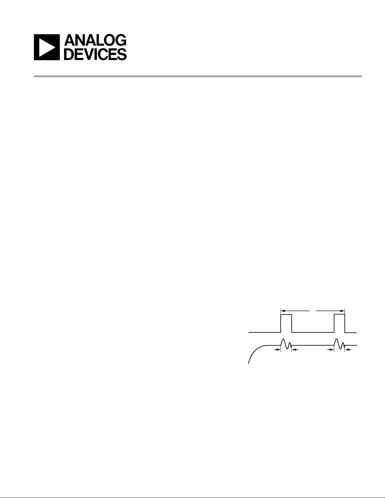
LCD NOISE
An LCD has many control signals, including display
refresh control, clock, and drive signals. During the display
refresh cycle in particular, noise is present in the system.
As the LCD horizontal lines are written, the noise is most
prominent. It has been shown that the noise in the system
is framed by an LCD control signal. This signal is related
to the LCD horizontal refresh phase, and may be the LCD
synchronization pulse or some other system-generated
signal that is active during the noisy period. Two typical
control signals on different types of LCD are the HSYNC
signal and the V
The frequency of the HSYNC signal can vary significantly,
depending on the type of LCD. The signal is normally only
asserted for a small fraction of its period, that is, its duty
cycle is not 50-50. The majority of the noise coupled onto
the touch screen occurs while this LCD signal is asserted.
Some residual noise may occur outside the HSYNC signal’s
active period.
A typical V
of 10 kHz, and a 50-50 duty cycle. In this case, noise may be
most prominent in the system at the signal transitions.
COM
Figure 1. Noise from the LCD Interferes with the
Touch Screen Measurements
signal.
COM
signal is show in Figure 2. It has a frequency
REV. 0
Page 2
AN-766
VOLTS (V)
6
5
4
3
2
1
0
–1
FIRST CONV
DELAY
ACQ1CONV
1
ACQ 2
ABORTED
RESTART
ACQ 2
CONV
2
ACQ
2
ACQ
3
ACQ
4
NOISY
PERIOD
NOISY
PERIOD
NOISY
PERIOD
1
STOP_ACQ
USER TOUCH
2 3
NO ACQ
HERE
ACQ
2
CONV
3
REV. 0
To cater for signals of different polarities on the STOPACQ
pin, there is a user-programmable register bit to indicate
whether the signal is active high or low. The POL bit is Bit
3 in Control Register 2, address 02h. See Table I for more
information.
To disable monitoring of STOPACQ, the pin should be tied
low if the signal polarity is active high, or tied high if the
signal polarity is active low. If the STOPACQ pin functionality is disabled, then any signal applied to the STOPACQ pin
is disregarded by the AD7877. The polarity bit defaults to 0
on power-up. The user must ensure that this bit contains
the correct value for the type of signal on STOPACQ.
Figure 2. Typical V
COM
Signal
THE AD7877 STOPACQ FEATURE
The AD7877 includes a feature to reduce the impact of LCD
noise on touch screen measurements. The AD7877 has an
ADC with sample-and-hold architecture. It is only during
the sample, or acquisition phase, of the ADC’s operation
that noise from the LCD screen has an effect on the ADC’s
measurements. During the hold, or conversion phase, the
noise has no effect, as the voltage at the input of the ADC
has already been acquired. The noise is present when the
LCD signal is active. So, no acquisitions should take place
during the LCD signal active period.
The LCD control signal should be connected to the AD7877
via the external STOPACQ pin. The AD7877 then monitors
this signal and ensures that no input signal to the ADC is
acquired during the noisy period.
While the STOPACQ pin is being monitored, the user can
drive the pin with a signal such as V
or HSYNC, or with
COM
some other suitable control signal. When the signal is
active, acquisitions on all input channels on the AD7877
are disabled, irrespective of the programmed mode of the
device. When the signal on the STOPACQ pin deasserts,
the ADC will reset to the start of the acquisition phase for
the next channel to be measured. By programming the
acquisition time, any noise from the LCD that is not framed
by the signal at STOPACQ can also be avoided. (For more
information on AD7877 modes and programming the
acquisition time, see the AD7877 data sheet.)
Table I. STOPACQ POL Bit Description
POL Bit Value STOPACQ Functionality
0 Input signal is active low:
Low signal level frames noise
1 Input signal is active high:
High signal level frames noise
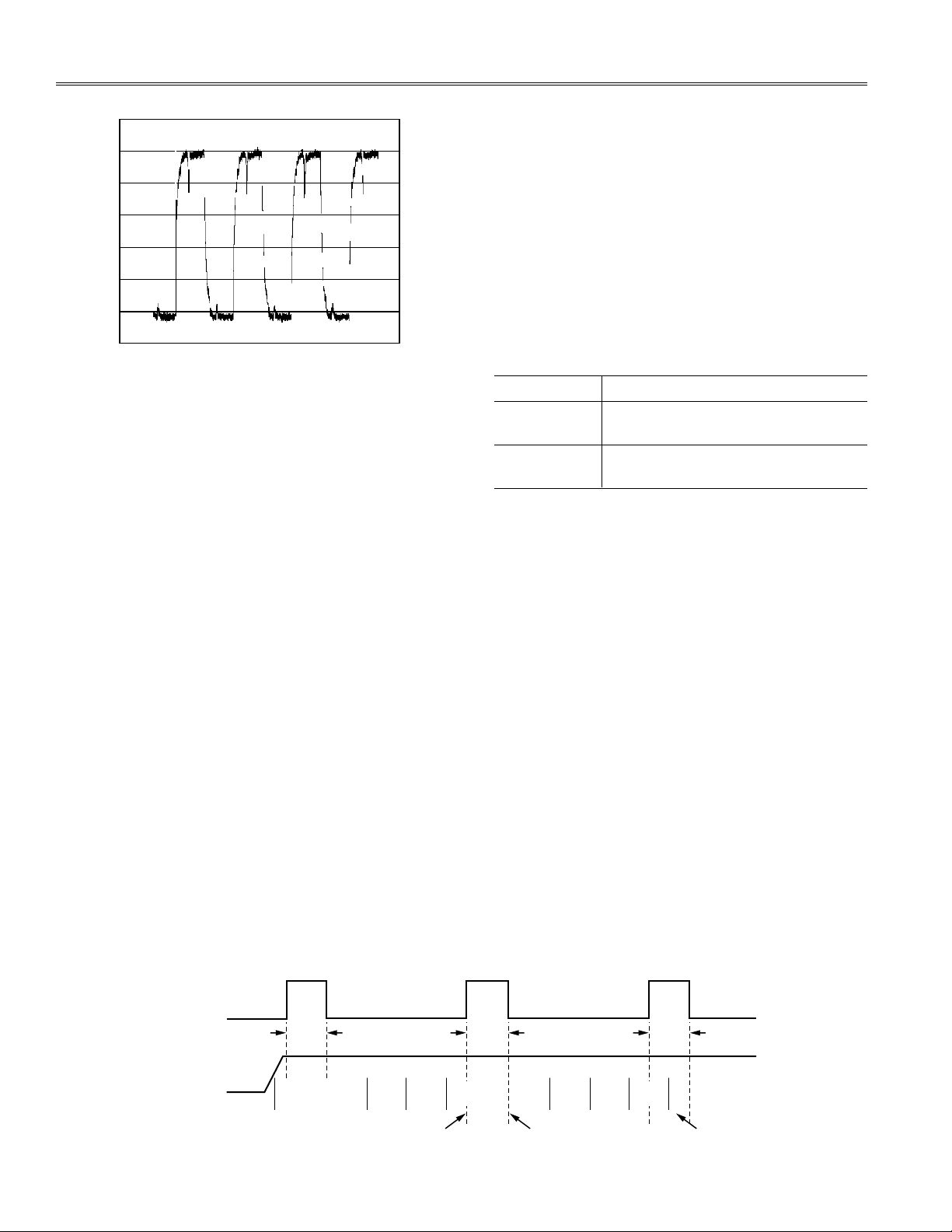
STOPACQ TIMING DETAILS
If the STOPACQ signal becomes active during an acquisition
cycle, the current acquisition is aborted. Any acquisition
data received up to this point is discarded. When STOPACQ
deasserts, the acquisition period is restarted from the
beginning. The acquisition time on the AD7877 can be
programmed by the user to be 2 s, 4 s, 8 s, or 16 s.
If the STOPACQ signal becomes active while the AD7877
is in a conversion phase, then the conversion goes ahead
as normal. However, the next acquisition phase does not
begin until the STOPACQ signal deasserts.
There is a first conversion delay before the first acquisition period in a sequence, and before every touch screen
measurement, to allow the touch screen to settle. This
delay is programmable by the user and can be 500 ns,
128 ms, 1.024 ms, or 8.19 ms. If the STOPACQ signal becomes active during the first conversion delay time, nothing
happens. The STOPACQ signal is ignored since noise from
the LCD screen will not impact the screen settling time.
This is illustrated in Figure 3.
Figure 3. Operation of the AD7877 when STOPACQ is Active
–2–
Page 3

AN-766
X ADC CODES
Y ADC CODES
3144
3142
3140
3138
3136
3134
3132
3130
3128
3126
837 838 839 840 841 842 843
STOPACQ
TIED TO GND
STOPACQ
TIED TO V
COM
The STOPACQ monitoring function is implemented on
all input channels to the ADC: X+, Y+, Y–, AUX1, AUX2,
AUX3, BAT1, BAT2, TEMP1, and TEMP2 channels. The
acquisition phase for any of these channels will be
affected by the STOPACQ signal.
TESTING THE STOPACQ FEATURE
The STOPACQ feature was tested using an HP iPAQ Pocket
PC. The iPAQ’s touch screen lies directly over the LCD, and
so it is reasonable to assume that noise is coupled from
the LCD onto the touch screen itself.
Both the touch screen connections and the V
COM
signals
were extracted from the iPAQ and connected to an AD7877
evaluation board. The touch screen contacts were connected
to the AD7877’s X+, Y+, X–, and Y– pins, while V
COM
was
connected to the STOPACQ pin via a resistor-divider
circuit. The AD7877’s conversion controls were then set
up as follows:
• Averaging: None
• First Conversion Delay: 1.024 ms
• Acquisition Time: 2 s
• Conversion Type: Differential
• STOPACQ Polarity: Active High
When STOPACQ is tied to V
, the AD7877 is not acquir-
COM
ing new data during that signal’s high time. The spread
of data values read back from the ADC is much smaller
in this situation. The largest difference between samples
is just 3 LSBs, for an error rate of 0.07%. It is clear that
most of the noise from the LCD is now being filtered by
the STOPACQ function.
Figure 4. ADC Codes when STOPACQ is Tied to
GND and V
COM
EXPERIMENTAL RESULTS
Figure 4 shows the results read back from the AD7877 for a
single point touched on the touch screen. A stylus was held
at one point on the touch screen while STOPACQ was tied
to ground, and again while STOPACQ was tied to V
When STOPACQ is tied to ground (and therefore the
acquisition phase is not interrupted), there is a much wider
spread of results from the AD7877. For the same point,
the values read back were as different as (838, 3128) and
(842, 4142). It is presumed that this spread in the results
is due to noise being coupled onto the touch screen from
the LCD.
REV. 0
COM
.
–3–
Page 4

AN-766
5000
4500
Y–(Z2)
TOUCHSCREEN
Y+
X+
4000
3500
3000
2500
2000
1500
1000
500
0
X+(Z1)
5000
4500
Y–(Z2)
TOUCHSCREEN
Y+
X+
4000
3500
3000
2500
2000
1500
1000
500
0
X+(Z1)
EXPERIMENTAL RESULTS: A CLOSER LOOK AT THE READ-BACK DATA
Figure 5. Noisy Data
Figure 5 shows a graph of the data being read back from
the AD7877 with STOPACQ tied to ground. Noise is causing
small variations to occur in the read-back data at regular
intervals. In comparison, Figure 6 shows read-back data
from the AD7877 when STOPACQ is tied to V
. There is
COM
no noise visible in the data.
CONCLUSION
The STOPACQ feature on the AD7877 is useful in eliminating noise from a touch screen system. In a real-world
application, such as an iPAQ personal digital assistant, the
STOPACQ feature reduced the noise present in the touch
screen measurements, giving more accurate results. It
should be noted that even more noise can be eliminated
from the system by using the AD7877’s automatic averaging and programmable acquisition times in conjunction
with STOPACQ. These features combine to reduce the total
noise in the system significantly, and thereby also reduce
the effort required by the host to get accurate positional
measurements. The AD7877 is the perfect fit for consumer
devices that require high accuracy touch screen measurements while keeping host interaction with the part to a
minimum.
REFERENCES
AD 7 8 77 Da t a Shee t . A n alog De vices, I n c . 2004.
http://www.analog.com/UploadedFiles/Data_Sheets/
59289336AD7877_a.pdf
AN05336–0–4/05(0)
Figure 6. Result Data with V
© 2005 Analog Devices, Inc. All rights reserved. Trademarks and registered trademarks are the property of their respective owners.
Tied to STOPACQ
COM
–4–
REV. 0
 Loading...