

Page 1
■ Overview
The AN6663S and AN6663SP are the forward/reverse drive
ICs for small DC motors. They provide 4 Kinds of outputs such
as foward rotation, reverse rotation, brake, and stop by the 2bit
input and are optimum as the drivers for the small motors of
100 to 150mA.
■ Features
•
Wide range of operating supply voltage
: V
CC (opr)
= 3 to 16V
•
Large power dissipation
(AN6663SP : PD = 1.45W when mounted)
•
Built-in low saturation voltage type output transistor
•
Built-in counter electromotive voltage suction diode
•
Input voltage at the TTL level : V
IL
= 0.8V or less,
V
IH
= 2V or more
AN6663S, AN6663SP
Bridge Drivers
1
2
3
4
0.4±0.25
0.6±0.31.27
0.1±0.1
0.3
0.15
0.65
1.5±0.2
5.0±0.3
4.2±0.3
6.5±0.3
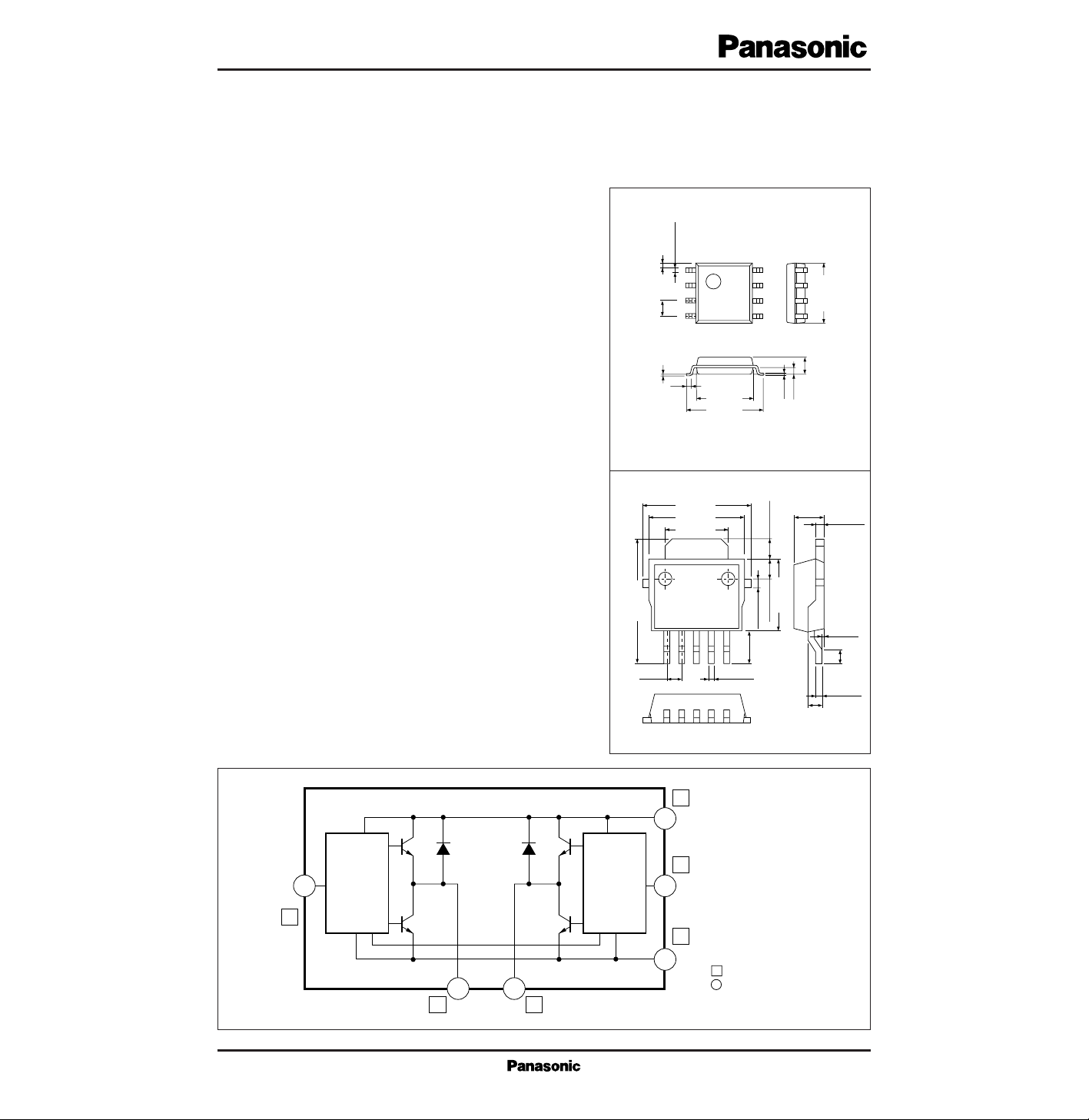
8-pin PANAFLAT Plastic Package (SOP008-P-0225A)
8
7
6
5
Unit : mmAN6663S
■ Block Diagram
0.5±0.1
12345
9.5±0.4
5.5±0.3
1.5±0.251.5±0.25
1.2±0.25
0.7±0.1
(2.5)
Unit : mmAN6663SP
1.27 0.5±0.1
0.5
+0.1
– 0.05
0 — 0.2
(1.1)
5-pin SIL Plastic Package (HSIP005-P-0000)
5.0±0.25
7.5±0.3
2.3±0.3
8.5±0.4
2 4
1
Input Logic
3
3
V
CC
4
Input Logic
6
GND
Fin
1
8
5
5
Pin No. : AN6663S
Pin No. : AN6663SP
Page 2
V
CC
I
CC
P
D
I
OP
T
opr
T
stg
V
mA
mW
mA
˚C
˚C
Parameter Symbol Rating Unit
■ Absolute Maximum Ratings (Ta=25˚C)
18
200
361
500
±150
±200
–20 to +75
–55 to +125
Supply voltage
Supply current
Power dissipation
Output peak current
Operating ambient temperature
Storage temperature
AN6663S
AN6663SP
AN6663S
AN6663SP
AN6663S
AN6663SP
Parameter Symbol Range
■ Recommended Operating Range (Ta=25˚C)
Operating supply voltage range
Output current
L input voltage
H input voltage
V
CC
I
O
I
O
V
IL
V
IH
3V to 16V
0mA to ±50mA
0mA to ±100mA
0V to 0.8V
2V to V
CC
Parameter Symbol Condition min typ max Unit
■ Electrical Characteristics (VCC=12V, Ta=25˚C)
Standby supply current
0.3I
CCSb
1.3 mA0.8
V
I1=VI2
=0.8V
Supply current
4I
CC
12 mA8
V
I1=VI2
=0.8V
H output voltage
10V
OH
V10.8
I
OH
=–100mA
Note)
L output voltage
V
OL
0.5 V
I
OL
=100mA
Note)
VI=2V→3V
Input impedance
7Z
in
13 kΩ10
Note) AN6663SP is IOH=–150mA, IOL=150mA
0.3
F/V
F
in
V
CC
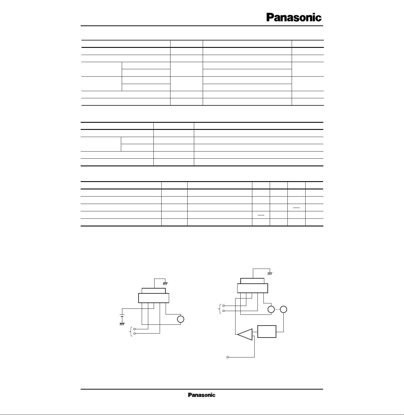
Microcomputer,
etc.
1 2 3 4 5
AN6663SP
M
+
–
F
in
Rotating Direction
Command
Speed Command
Voltage
Voltage Amplifier
Tachometer Generator
Sensor, etc.
1 2 3 4 5
AN6663SP
M
1. Basic Circuit 2. When Controlling Speed
■ Application Circuit
• AN6663SP
Page 3

■ Pin Descriptions
Pin No.
1
2
3
4
5
8
1
3
4
5
Approx. 10kΩ
Approx. 10kΩ
Output pin 1 V
O1
Input pin 1 V
I1
Supply voltage V
CC
Input pin 2 V
I2
Output pin 2 V
O2
Pin to connect the motor coil
Pin to input the supply voltage
Pin to connect the motor coil
I/O impedance Equivalent circuitDescriptionPin name
AN6663SAN6663SP
Input pin to determine the
motor rotating direction
Input pin to determine the
motor rotating direction
1
8
*
5
5
*
2
10kΩ
50µA
10kΩ
1
*
4
10kΩ
50µA
10kΩ
4
*
The numbers marked with * are the AN6663S
F/V
V
CC
Microcomputer, etc.
AN6663S
M
M
+
–
Rotation Direction Command
Voltage Amplifier
Tachometer Generator, etc.
Sensor, etc.
1. Basic Circuit 2. When Controlling Speed
1 3 42
8 6 57
AN6663S
1 3 42
8 6 57
Speed Command
Voltage
■ Application Circuit(Cont.)
• AN6663S
Page 4

■ Pin Descriptions (Cont.)
Pin No.
FIN 6
2, 7
Ground pin GND
NC
Ground pin
NC for the AN6663S
I/O impedance Equivalent circuitDescriptionPin name
AN6663SAN6663SP
2 The input voltage of the input pins VI1 and VI2 can be applied up to twice larger than VCC (it should not exceed 18V).
V
I1
L
H
L
H
V
I2
L
L
H
H
V
O1
HiZ
L
H
L
V
O2
HiZ
H
L
L
Motor stop
Forward rotation
Reverse rotation
Brake
Motor operation
■ Supplementary Explanation
• Precautions on Use
1 Truth table
 Loading...