

Page 1
AN-640
APPLICATION NOTE
One Technology Way • P.O. Box 9106 • Norwood, MA 02062-9106 • Tel: 781/329-4700 • Fax: 781/326-8703 • www.analog.com
Synchronizing Multiple AD9777s Using DATACLK Input Mode
By Steve Reine
As stated in its data sheet, there are two primary methods
for clocking the AD9777. The fi rst is with the PLL enabled,
where the clock applied to the differential clock inputs is
the same speed as the input data rate. The internal PLL
then performs the internal clock multiplication needed
to operate the interpolation fi lters and DAC. The second
method is to disable the PLL and to apply an external
clock at the DAC output sample rate. In this mode, internal
dividers provide the clocks needed for the internal digital
fi lters and also generate the DATACLK and ONEPORTCLK
clocks needed for external data synchronization.
For applications with the most stringent noise requirements, the AD9777 can be operated with the internal PLL
disabled. See the AD9777 data sheet for more details on
performance in this mode. With the PLL disabled, the
DATACLK output can be used to synchronize external
data at the AD9777 digital inputs. Setup and hold times
for this mode are given in the data sheet. This works very
well when only a single AD9777 needs to be synchronized with external data. In applications where multiple
AD9777s are used and their external digital data must
be synchronized to a single clock, using DATACLK as an
output will not work correctly. DATACLK out may fall on
one of several different clock edges of the differential
input clock, and there is no way to synchronize multiple
AD9777s to make sure that DATACLK out falls on the
same edge for every part. To overcome this obstacle, the
AD9777 can be programmed so that the DATACLK pin
functions as an input. In this mode, the user drives the
AD9777 with two clocks, the external differential DAC
clock, as well as the external clock on the DATACLK pin.
Note that this mode is available only when the PLL is
disabled and the AD9777 is in two-port data mode. To set
the device to this mode, program (through the SPI port)
input register 02h, Bit 3, to a Logic 1.
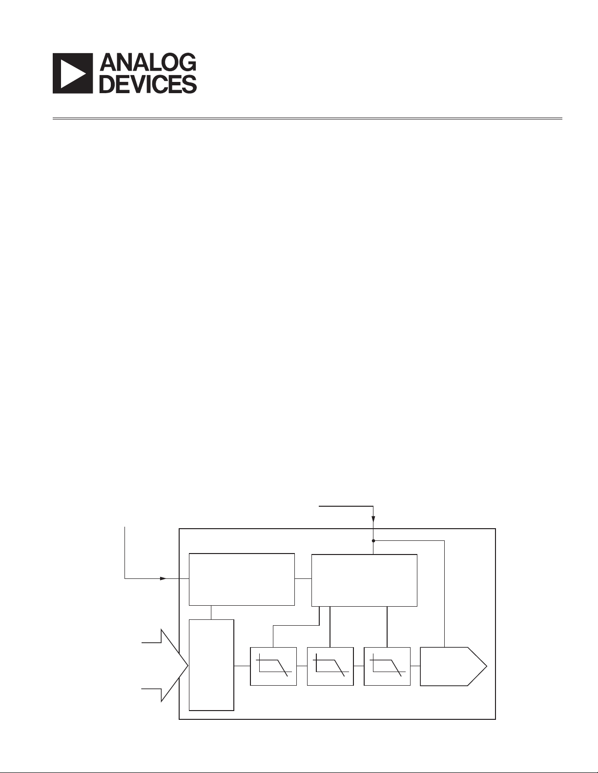
As shown in Figure 1, an internal state machine is used to
perform the synchronization between the DAC and data
clocks. Synchronization occurs when a rising edge is
applied to the state machine by way of the DATACLK
pin. When this rising edge occurs in advance of a DAC
clock rising edge by a time t
, the input data is syn-
SMS
chronized to the third following edge of the DAC clock.
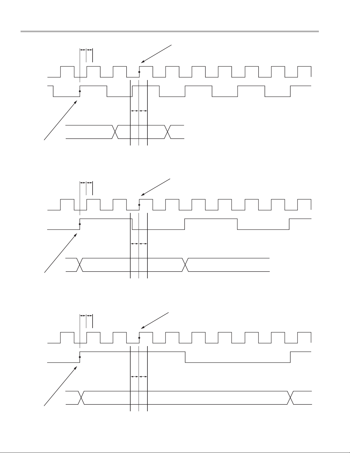
Figures 2a–2c show the timing in all three interpolation
modes. Note the timing required between the DAC and
data clock and that the set up and hold times of the digital
inputs are with respect to the third following edge of the
DAC clock.
REV. 0
EXTERNALLY APPLIED DAC CLOCK
EXTERNALLY APPLIED DATA CLOCK
DATACLK
(INPUT)
DIGITAL
DATA
INPUT
STATE MACHINE
INPUT
LATCHES
INTERNAL DIVIDERS
INTERPOLATION FILTERS
(CLK+, CLK–)
DAC
Figure 1. Driving the AD9777 with Separate DAC and Data Clocks Using DATACLK Input
Page 2
AN-640
t
t
SMS
SMH
DAC CLOCK
DATA CLOCK
DIGITAL INPUT DATA
SYNCHRONIZING EDGE OF DATA CLOCK
t
t
SMS
SMH
DAC CLOCK
SENSITIVE EDGE OF DAC CLOCK
tSt
H
Figure 2a. Data Clock Input Mode Timing with 2 Interpolation
SENSITIVE EDGE OF DAC CLOCK
t
SMS
t
SMH
t
= –1ns
S
t
= +0.5ns
H
= +2ns
= –1ns
DATA CLOCK
SYNCHRONIZING EDGE OF DATA CLOCK
t
t
SMS
SMH
DAC CLOCK
DATA CLOCK
tSt
H
DIGITAL INPUT DATA
Figure 2b. Data Clock Input Mode Timing with 4 Interpolation
SENSITIVE EDGE OF DAC CLOCK
tSt
H
t
SMS
t
SMH
t
= –1ns
S
t
= +0.5ns
H
t
SMS
t
SMH
t
= –1ns
S
t
= +0.5ns
H
= +2ns
= –1ns
= +2ns
= –1ns
SYNCHRONIZING EDGE OF DATA CLOCK
DIGITAL INPUT DATA
Figure 2c. Data Clock Input Mode Timing with 8 Interpolation
–2–
REV. 0
Page 3

If the rising edge of the data clock occurs after the time
t
, the synchronization will be delayed by one cycle of
SMH
the DAC clock.
An internal state machine controls the DAC latch timing
in all modes of operation. This state machine is updated
on every rising edge of the DAC clock. The output of the
state machine updates the AD9777 input latches at a rate
dependent on the DAC clock speed and the interpolation
rate. With DATACLK programmed as an input, the state
machine is reset on every rising edge of DATACLK. For
this reason, if DATACLK were to stop, and the input data
were to continue uninterrupted, the AD9777 may appear
to be operating normally (i.e., state machine is still running). However, synchronization will likely be lost very
quickly and the keep out windows defi ned by t
and t
may shift in time randomly.
SMH
, tH, t
S
SMS
AN-640
,
REV. 0
–3–
Page 4

E03617–0–2/03(0)PRINTED IN U.S.A.
© 2003 Analog Devices, Inc. All rights reserved. Trademarks and registered trademarks are the property of their respective companies.
–4–
 Loading...