

Page 1

ICs for TV
AN5534N
Vertical deflection output IC
■ Overview
The AN5534N is a vertical deflection output IC for
television and CRT monitor. Incorporating a sawtooth
wave generator, this IC enables you to form an AC/DC
feedback-loop by itself only.
■ Features
• Built-in stable sawtooth wave generator independent of
input pulse width variation
• Built-in 50 Hz/60 Hz changeover circuit
• Minimum fly-back time of saw-tooth wave signal:
100 µs
■ Applications
• Televisions and CRT displays
■ Block Diagram
20.0±0.3
28.0±0.3
29.75±0.30
φ3.6
(10.0)(10.0)
R1.8
0.6
1.2±0.1
HSIP012-P-0000A
7.7±0.3
(12.5)
19.1±0.3
21.9±0.3
(1.2)
Unit: mm
121
+0.15
(1.27) (1.27) (1.3)
2.54
+0.10
–0.05
0.6
–0.05
0.25
3.5±0.3
1.45±0.151.80±0.15
29.6±0.3
1
Vert.
trig.
input
9 V
CC1
V
Ramp
generator
2
3
Vert. trig. input
Vert. size
control SW
5
4
50 Hz/60 Hz SW
Vert. drive Vert. out
Pump up
9
6
7
8
26 V
CC2
V
10
GND
11
12
1
Page 2
AN5534N ICs for T V
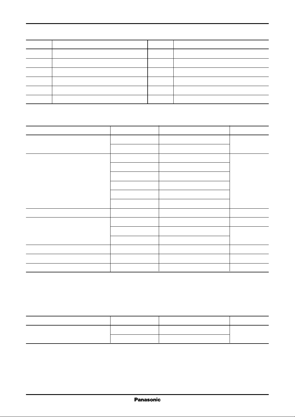
■ Pin Descriptions
Pin No. Description
1 Power supply 1
2 Vertical pulse input
3 Vertical amplitude control
4 50 Hz/60 Hz changeover
5 Saw-tooth wave generation
6 AC/DC feedback input
■ Absolute Maximum Ratings
Parameter Symbol Rating Unit
Supply voltage V
Pin voltage V
Supply current I
Pin current I
Power dissipation P
Operating ambient temperature
Storage temperature
Note)1.Do not apply external currents or voltages to any pins not specifically mentioned.
For circuit currents, '+' denotes current flowing into the IC, and '−' denotes current flowing out of the IC.
2.
: Except for the operating ambient temperature and storage temperature, all ratings are for Ta = 25°C.
3. *
*
*
CC1
V
CC2
2−9
V
4−9
V
5−9
V
6−9
V
10−9
V
11−9
CC1
3
I
8
I
10
D
T
opr
T
stg
Pin No. Description
7 Power supply 2
8 Pulse amplification
9 GND
10 Vertical output
11 Power supply for vertical output
12 Prevention from oscillation
15 V
30
0 to 2.7 V
0 to V
1−9
0 to V
1−9
0 to V
1−9
0 to 61
0 to 61
20 mA
− 0.2 to 0 mA
−1.8 to +1.8 A[0-p]
−2.2 to +2.2
27 W
−20 to +70 °C
−55 to +150 °C
■ Recommended Operating Range
Parameter Symbol Range Unit
Supply voltage V
2
CC1
V
CC2
7 to 15 V
10 to 30
Page 3

ICs for TV AN5534N
■ Electrical Characteristics at Ta = 25°C
Parameter Symbol Conditions Min Typ Max Unit
Load short-circuit R. short V
Deflection current I
HP−PVCC2
Vertical amplifier distortion T. H. D
factor Sine wave 1 kHz
Input threshold voltage V2Refer to the "• Test method" 0.5 0.7 1.0 V
Sawtooth wave generating start V
5
voltage
Middle point voltage V
Idling current I
Output saturation voltage (lower) V
Output saturation voltage (upper) V
Pump up charging saturation V
MID
11
11−10V7
10−9V7
8−9V7
voltage
Pump up discharging saturation V
7−8V7
voltage
= 26 V Free from breakdown
CC2
= 26 V, V5 = 2.2 V[p-p] 1.8 2.0 2.2 A[p-p]
Sine wave 1 kHz
= 26 V, V5 = 2.2 V[p-p] 2.0 5.0 %
HVCC2
Refer to the "• Test method" 3.6 4.5 5.4 V
11.5 12.8 14.1 V
21.0 36.0 51.0 mA
= GND 3.0 4.0 V
= GND 1.5 2.5 V
= GND 0.2 0.5 V
= GND 3.0 4.0 V
• Test method
1. Input threshold voltage (V
)
2
H2 voltage at which a saw-tooth wave shown below is generated at pin 5 when H2 voltage is gradually increased
from 0 V
2. Saw-tooth wave generating start voltage (V
)
5
Lower level voltage of a sawtooth wave which generates at pin 5
Input pulse of pin 2
H
0 V
Sawtooth wave generates at pin 5
H
L
2
5
5
3
Page 4

AN5534N ICs for T V
■ Usage Notes
• Inter-pin short-circuit test result
1
2
3
4
5
6
7
8
9
10
11
12
Pin No.
Test conditions: V
= 30 V, DC power supply (30 V, 5 A)
CC
●: IC does not break down even if pins are short-circuited.
●
●
●
●
●●
▲
×: IC breaks down if pins are short-circuited.
▲: IC does not break down even if pins are short-circuited, but it causes
over-current flows in the external power supply circuit.
●●●●
●●●●●
▲
●● ●
●
●●●●●●
▲●●●●●
●●● ●●●
●●●
▲
▲
●
▲
▲
●
▲
×
▲
×
×
●●● ●
●
×
▲
●●●●●●●●●●
1
23456789101112
Pin 4 (50 Hz/60 Hz changeover) = V
CC1
Pin 4 (50 Hz/60 Hz changeover) = GND
●
■ Technical Information
1. PD Ta curves of HSIP012-P-0000A
50
45
40
35
(W)
30
D
Infinite heat sink
25
20
15
Power dissipation P
10
5
Without heat sink
= 48°C/W
R
th (j−a)
0
20 40 60 80 100 120 140 160
P
T
D
a
: R
= 3°C/W
th (j−c)
:
Ambient temperature Ta (°C)
4
Page 5

ICs for TV AN5534N
■ Technical Information (continued)
2. Area of safe operation (ASO) of output transistor forward-biased
2.2
1
)
A
(
O
1.0
0.1
Output transistor emitter current I
Ta = 25°C
Single pulse
10 ms
1.0 s
0.01
Note)
The maximum value of deflection current for the actual use is suitable within ±1.5 A[0-p] (3 A[p-p]).
■ Application Circuit Example
Ramp
generator
3
50 Hz/60 Hz
60 Hz
27 kΩ
Vert. height vol.
V
CC1
9 V
47 µF
1
1.5 V
0 V
Vert.
trig.
input
2
V ert.
trig.
input
10 10060
)
VCE (V
(ASO curve of deflection output Tr)
Vert. drive Vert. out
Vert. size
Pump up
control SW
4
5
6
7
V
CC2
SW
26 V
50 Hz
47 µF
0.68 µF
18 kΩ
100 kΩ
33 kΩ
8
100 µF
3.9 kΩ
1 µF
9
47 kΩ
10
D.Y.
1 000 µF
1.5 Ω
(0.5 W)
11
12
5
 Loading...